lock OPEL VIVARO C 2020.25 Manual user
[x] Cancel search | Manufacturer: OPEL, Model Year: 2020.25, Model line: VIVARO C, Model: OPEL VIVARO C 2020.25Pages: 287, PDF Size: 28.79 MB
Page 203 of 287

Driving and operating201ActivationInfo Display without touchscreen
Press Qto activate the system.
The system is switched on when the
LED in the button is illuminated.
Info Display with touchscreen
The system can be activated in the
vehicle personalisation 3 124.
The system is only operable at
vehicle speeds above 60 km/h and if
lane markings are available.
When the system recognises an
unintended lane change, the control
indicator ) flashes yellow.
Simultaneously a chime sounds.
Deactivation
Info Display without touchscreen
Press Q to deactivate the system.
The LED in the button Q
extinguishes.Info Display with touchscreen
The system can be deactivated in the
vehicle personalisation 3 124.
At speeds below 60 km/h the system
is inoperable.
Fault
Info Display without touchscreen
The LED of the Q flashes.Info Display with touchscreen
The control indicator Q flashes and
an error message is displayed.
Seek the assistance of a workshop.
The system cannot operate when no
lane marking is detected.
System limitations
The system may not operate properly
when:
● vehicle speed is below 60 km/h● driving on winding or hilly roads
● driving in the dark
● weather limits visibility, such as fog, rain, or snow
● the camera is blocked by snow, ice, slush, mud, dirt, windscreen
damage or affected by foreign
items, e.g. stickers
● the sun is shining directly into the
camera lens
● close vehicles ahead
● banked roads
● road edges
● roads with poor lane markings
● sudden lighting changes
Driver alert
The driver alert system monitores the driving time and the vigilance of the
driver. Monitoring the vigilance of the
Page 206 of 287
204Driving and operatingFor more information, contact a
dealer or a qualified workshop.Caution
The use of any other type of (bio)
fuel (vegetable or animal oils, pure
or diluted, domestic fuel etc.) is
strictly prohibited (risk of damage
to the engine and fuel system).
Note
The only Diesel additives authorised for use are those that meet the
B715000 standard.
Low temperature operation
At temperatures below 0 °C, some
diesel products with biodiesel blends may clog, freeze or gel, which mayaffect the fuel supply system. Starting
and engine operation may not work
properly. Make sure to fill winter
grade diesel fuel at ambient
temperatures below 0 °C.
Arctic grade diesel fuel can be used
in extreme low temperatures below
-20 °C. Using this fuel grade in warm
or hot climates is not recommended
and may cause engine stalling, poor starting or damage on the fuel
injection system.
Refuelling9 Danger
Before refuelling, switch off
ignition and any external heaters
with combustion chambers.
Follow the operating and safety
instructions of the filling station
when refuelling.
9 Danger
Fuel is flammable and explosive.
No smoking. No naked flames or
sparks.
If a smell of fuel can be noticed
inside the vehicle, have the cause of this remedied immediately by aworkshop.
A label with symbols at the fuel filler
flap is indicating the allowed fuel
types. In Europe the pump nozzles of
the filling stations are marked with
these symbols. Refuel only the
allowed fuel type.Caution
In case of misfuelling, do not
switch on ignition.
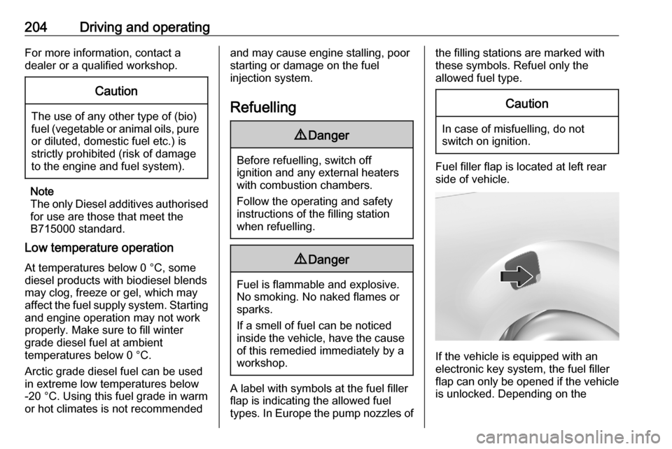
Fuel filler flap is located at left rear
side of vehicle.
If the vehicle is equipped with an
electronic key system, the fuel filler
flap can only be opened if the vehicle
is unlocked. Depending on the
Page 207 of 287
Driving and operating205version, release the fuel filler flap by
pushing the flap or pulling at the right bottom corner.
Depending on the version, place the
key in the lock and unlock the cap.
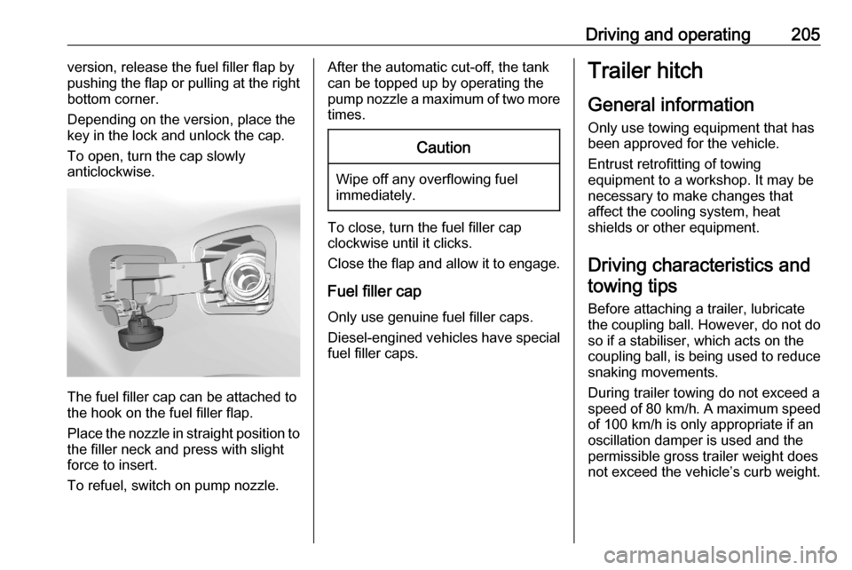
To open, turn the cap slowly
anticlockwise.
The fuel filler cap can be attached to
the hook on the fuel filler flap.
Place the nozzle in straight position to the filler neck and press with slight
force to insert.
To refuel, switch on pump nozzle.
After the automatic cut-off, the tank can be topped up by operating the
pump nozzle a maximum of two more
times.Caution
Wipe off any overflowing fuel
immediately.
To close, turn the fuel filler cap
clockwise until it clicks.
Close the flap and allow it to engage.
Fuel filler cap
Only use genuine fuel filler caps.
Diesel-engined vehicles have special fuel filler caps.
Trailer hitch
General information
Only use towing equipment that has
been approved for the vehicle.
Entrust retrofitting of towing
equipment to a workshop. It may be
necessary to make changes that
affect the cooling system, heat
shields or other equipment.
Driving characteristics and towing tips
Before attaching a trailer, lubricate
the coupling ball. However, do not do so if a stabiliser, which acts on thecoupling ball, is being used to reduce
snaking movements.
During trailer towing do not exceed a
speed of 80 km/h. A maximum speed
of 100 km/h is only appropriate if an
oscillation damper is used and the
permissible gross trailer weight does
not exceed the vehicle’s curb weight.
Page 209 of 287
Driving and operating207Always aim for the maximum vertical
coupling load, especially in the case
of heavy trailers. The vertical coupling
load should never fall below 25 kg.
Rear axle load
When the trailer is coupled and the
towing vehicle fully loaded, the
permissible rear axle load (see
identification plate or vehicle
documents) may be exceeded by
60 kg , the gross vehicle weight rating
must not be exceeded. If the
permissible rear axle load is
exceeded, a maximum speed of
100 km/h applies.
Towing equipment Depending on version the vehicle canbe fitted with a detachable or a fixed
coupling ball bar.
Type ACaution
When operating without a trailer,
remove the coupling ball bar.
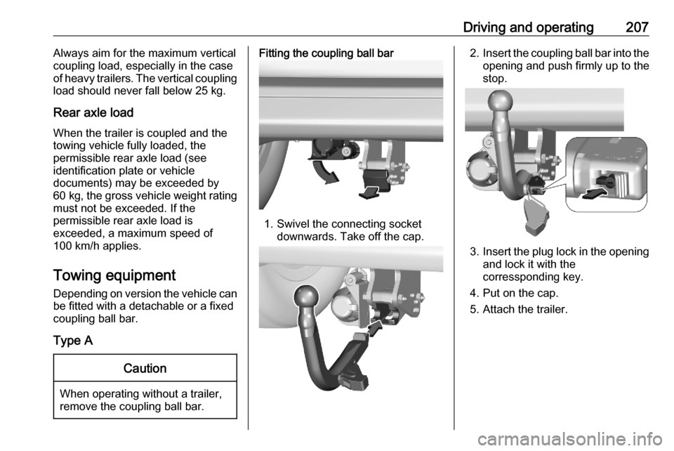
Fitting the coupling ball bar
1. Swivel the connecting socket downwards. Take off the cap.
2.Insert the coupling ball bar into the
opening and push firmly up to the stop.
3. Insert the plug lock in the opening
and lock it with the
corressponding key.
4. Put on the cap.
5. Attach the trailer.
Page 210 of 287
208Driving and operating
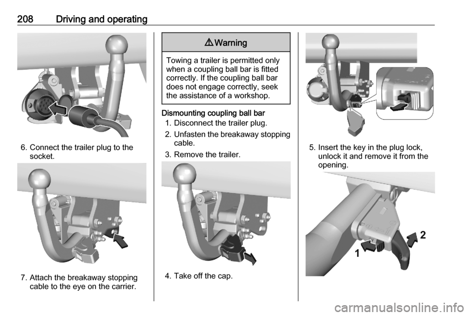
6. Connect the trailer plug to thesocket.
7. Attach the breakaway stoppingcable to the eye on the carrier.
9 Warning
Towing a trailer is permitted only
when a coupling ball bar is fitted correctly. If the coupling ball bardoes not engage correctly, seekthe assistance of a workshop.
Dismounting coupling ball bar
1. Disconnect the trailer plug.
2. Unfasten the breakaway stopping
cable.
3. Remove the trailer.
4. Take off the cap.
5. Insert the key in the plug lock, unlock it and remove it from the
opening.
Page 215 of 287
Vehicle care213● Open the bonnet, close all doorsand lock the vehicle.
● Disconnect the clamp from the negative terminal of the vehicle
battery. Note that all systems are
not functional, e.g. anti-theft
alarm system.
Putting back into operation
When the vehicle is to be put back into
operation:
● Connect the clamp to the negative terminal of the vehicle
battery. Initialize the power
windows 3 42.
● Check tyre pressure.
● Fill up the washer fluid reservoir.
● Check the engine oil level.
● Check the coolant level.
● Fit the number plates if necessary.End-of-life vehicle recovery
Information on end-of-life vehicle
recovery centres and the recycling of
end-of-life vehicles is available on our website, where legally required. Only
entrust this work to an authorised
recycling centre.Vehicle checks
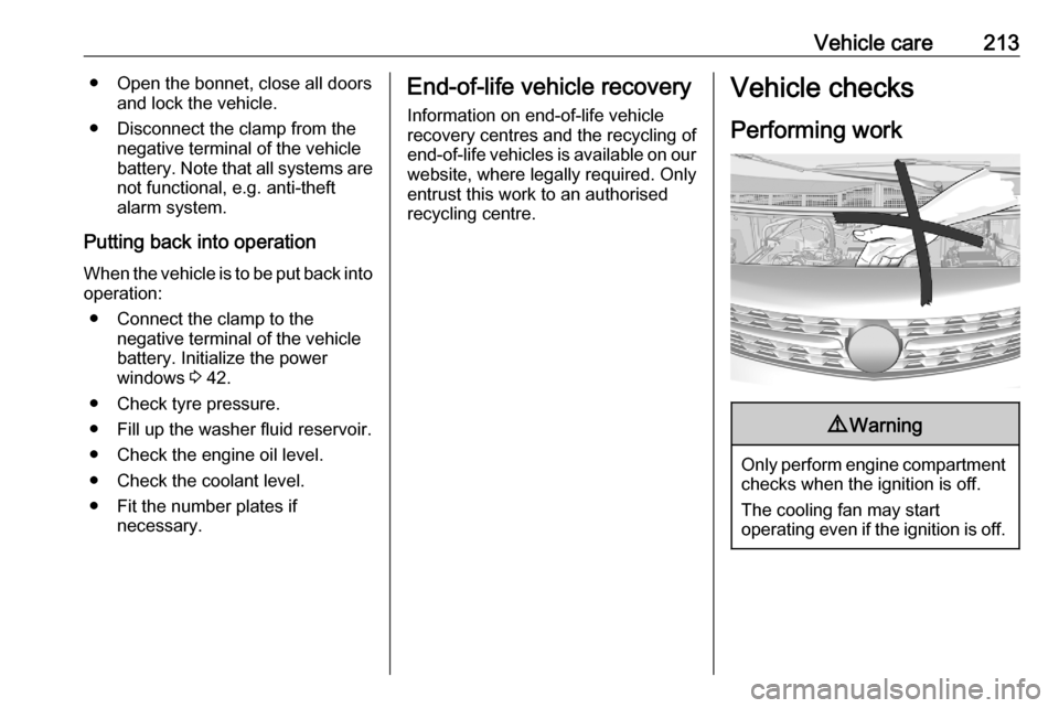
Performing work9 Warning
Only perform engine compartment
checks when the ignition is off.
The cooling fan may start
operating even if the ignition is off.
Page 227 of 287
Vehicle care225
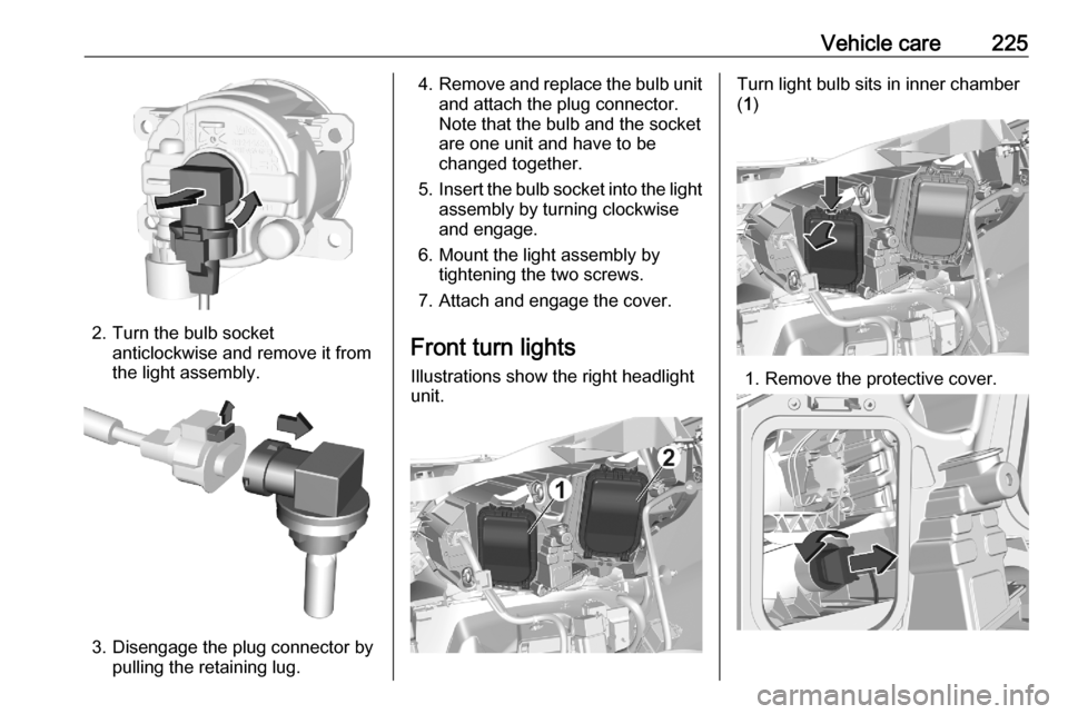
2. Turn the bulb socketanticlockwise and remove it from
the light assembly.
3. Disengage the plug connector by pulling the retaining lug.
4.Remove and replace the bulb unit
and attach the plug connector.
Note that the bulb and the socket
are one unit and have to be
changed together.
5. Insert the bulb socket into the light
assembly by turning clockwise
and engage.
6. Mount the light assembly by tightening the two screws.
7. Attach and engage the cover.
Front turn lights Illustrations show the right headlight
unit.Turn light bulb sits in inner chamber
( 1 )
1. Remove the protective cover.
Page 228 of 287

226Vehicle care2. Rotate the bulb socketanticlockwise to disengage and
withdraw from the reflector.
3. Slightly press down the bulb, turn it anticlockwise and remove it
from the socket.
4. Replace and insert the new bulb into socket by turning clockwise.
5. Insert the bulb socket into the reflector and turn clockwise.
Tail lights
Tail light assembly All body styles except platform cab
1. Vehicles with a cover hiding the lower tail light assembly screw:
remove cover by carefully
releasing its retaining lugs with a
screwdriver and tilting the cover
slightly towards the outside.
2. Unscrew and remove the two screws.
3. Vehicles with air vent or coverbehind the tail light, in the trim:
Remove air vent or cover.
Page 230 of 287
228Vehicle care12. Clip in cover which may havecovered the lower tail light
assembly screw.
13. Attach cover or air vent behind the
tail light if removed before.
Platform Cab
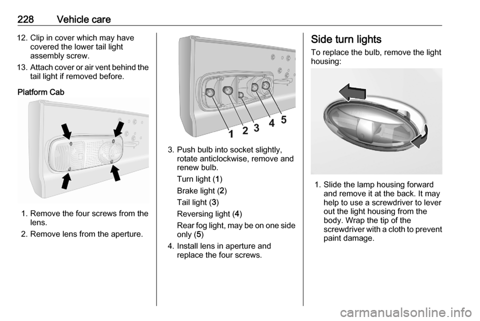
1. Remove the four screws from the lens.
2. Remove lens from the aperture.
3. Push bulb into socket slightly, rotate anticlockwise, remove and
renew bulb.
Turn light ( 1)
Brake light ( 2)
Tail light ( 3)
Reversing light ( 4)
Rear fog light, may be on one side
only ( 5)
4. Install lens in aperture and replace the four screws.
Side turn lights
To replace the bulb, remove the light
housing:
1. Slide the lamp housing forward and remove it at the back. It may
help to use a screwdriver to lever
out the light housing from the
body. Wrap the tip of the
screwdriver with a cloth to prevent
paint damage.
Page 231 of 287

Vehicle care229
2.Pull the retaining lug upwards and
remove the bulb socket from the
plug connector.
3. Replace the complete unit.
4. Insert left end of the lamp, slide to
the left and insert right end.
Centre high-mounted brake light
Vehicles with hinged doors or
tailgate
1. Open the rear doors.
2. a) vehicles with tailgate:
Loose the inner trim from clips by
swiveling it upwards and
downwards. Pull trim off carefully.
b) vehicles with hinged doors:
Wrap a cloth around the tip of a
slot screwdriver to prevent paint
damage. Remove the inner cover
or air vent with the screwdriver.
3. Push the brake light assembly carefully out through the recess.
4. Detach the cable from the retainer
in the light assembly.
5. Remove the socket of the defect bulb by turning it a quarter turn
anti-clockwise.
6. Renew bulb.
7. Install brake light assembly like explained above, in reversed
order.