lock OPEL ZAFIRA C 2017.25 Manual user
[x] Cancel search | Manufacturer: OPEL, Model Year: 2017.25, Model line: ZAFIRA C, Model: OPEL ZAFIRA C 2017.25Pages: 291, PDF Size: 9.02 MB
Page 184 of 291

182Driving and operatingRadar unit
The radar unit is mounted behind the
radiator grille below the brand
emblem.
9 Warning
The radar unit was aligned
carefully during manufacture.
Therefore, after a frontal accident, do not use the system. The front
bumper may appear to be intact,
however the sensor behind can be
out of position and react
incorrectly. After an accident,
consult a workshop to verify and
correct the adaptive cruise control
sensor position.
Settings
Settings can be changed in the
vehicle personalisation menu in the
Info-Display.
Select the relevant setting in
Settings in the Info-Display.
Info-Display 3 121.
Vehicle personalisation 3 125.
Fault
If the adaptive cruise control does not work due to temporary conditions
(e.g. blockage by ice) or if there is a
permanent system error, then a
message is displayed in the Driver
Information Centre.
Vehicle messages 3 123.
Forward collision alert The forward collision alert can help to
avoid or reduce the damage caused
by front-end crashes.
A vehicle ahead is indicated by a
control indicator A.
If a vehicle directly ahead is
approached too quickly, a warning
chime and alert in the Driver
Information Centre is provided.
A precondition is that forward collision
alert is activated in the vehicle
personalisation menu 3 125 or that it
is not deactivated by pressing V
(depending on the system, see
following).
Page 187 of 291
Driving and operating185Alerting the driver
The vehicle ahead control indicator
A illuminates green in the instrument
cluster when the system has detected
a vehicle in the driving path.Caution
The colour lighting of this control
indicator does not correspond to
local traffic laws on following
distance. The driver bears full
responsibility for maintaining safe
following distance according to
applicable traffic rules, weather
and road conditions etc. at all
times.
When the distance to a preceding
moving vehicle gets too small or when
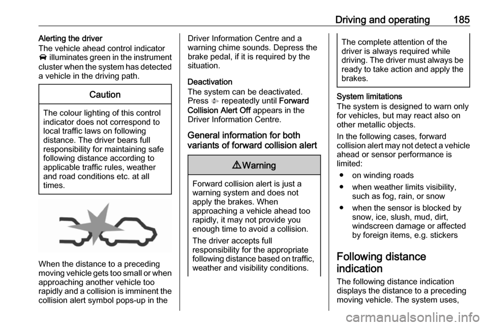
approaching another vehicle too rapidly and a collision is imminent the collision alert symbol pops-up in the
Driver Information Centre and a
warning chime sounds. Depress the
brake pedal, if it is required by the
situation.
Deactivation
The system can be deactivated.
Press V repeatedly until Forward
Collision Alert Off appears in the
Driver Information Centre.
General information for both
variants of forward collision alert9 Warning
Forward collision alert is just a
warning system and does not
apply the brakes. When
approaching a vehicle ahead too
rapidly, it may not provide you
enough time to avoid a collision.
The driver accepts full
responsibility for the appropriate
following distance based on traffic, weather and visibility conditions.
The complete attention of the
driver is always required while
driving. The driver must always be
ready to take action and apply the
brakes.
System limitations
The system is designed to warn only for vehicles, but may react also onother metallic objects.
In the following cases, forward
collision alert may not detect a vehicle ahead or sensor performance is
limited:
● on winding roads
● when weather limits visibility, such as fog, rain, or snow
● when the sensor is blocked by snow, ice, slush, mud, dirt,
windscreen damage or affected
by foreign items, e.g. stickers
Following distance indication
The following distance indication
displays the distance to a preceding
moving vehicle. The system uses,
Page 189 of 291

Driving and operating187Brake preparation system
When approaching a vehicle ahead
so quickly that a collision is likely, the brake preparation system slightlypressurises the brakes. This reduces
the response time, when a manual or automatic braking is requested.
The brake system is prepared so that braking can occur more rapidly.
Emergency automatic braking
After the brake preparation and just
before the imminent collision, this
function automatically applies limited
braking to reduce the impact speed of
the collision.
Forward looking brake assist
In addition to brake preparation
system and emergency automatic
braking, the forward looking brake
assist function makes the brake assist more sensitive. In this way,
depressing the brake pedal slightly
results immediately in a strong
braking. This function helps the driver
brake quicker and stronger before the imminent collision.9 Warning
Active emergency braking is not
designed to apply strong
autonomous braking or to avoid automatically a collision. It is
designed to reduce the vehicle
speed before collision. It may not
react on stopped vehicles,
pedestrians or animals. After a
sudden lane change, the system
needs a certain time to detect the
next preceding vehicle.
The complete attention of the
driver is always required while
driving. The driver shall always be ready to take action and apply the brakes and steer to avoid
collisions. The system is designed
to work with all occupants wearing their seat belts.
System limitations
The active emergency braking has
limited or no function during rain,
snow or heavy dirt, as the radar
sensor can be covered by a water
film, dust, ice or snow. In case of
sensor blockage, clean the sensor
cover.
In some seldom cases the active
emergency braking system may
provide a short automatic braking in
situations that seem to be
unnecessary, for instance due to
traffic signs in a curve or due to
vehicles in another lane. This is
acceptable operation, the vehicle
does not need service. Firmly apply
the accelerator pedal to override the
automatic braking.
Settings
Settings can be changed in the
vehicle personalisation menu in the
Info-Display.
Select the relevant setting in
Settings in the Info-Display.
Vehicle personalisation 3 125.
Fault
In the event of a system service
requirement, a message is displayed
in the Driver Information Centre.
Page 205 of 291
Driving and operating203
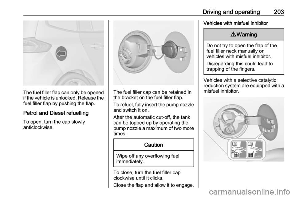
The fuel filler flap can only be opened
if the vehicle is unlocked. Release the
fuel filler flap by pushing the flap.
Petrol and Diesel refuelling To open, turn the cap slowly
anticlockwise.The fuel filler cap can be retained in
the bracket on the fuel filler flap.
To refuel, fully insert the pump nozzle
and switch it on.
After the automatic cut-off, the tank can be topped up by operating the
pump nozzle a maximum of two more
times.
Caution
Wipe off any overflowing fuel
immediately.
To close, turn the fuel filler cap
clockwise until it clicks.
Close the flap and allow it to engage.
Vehicles with misfuel inhibitor9 Warning
Do not try to open the flap of the
fuel filler neck manually on
vehicles with misfuel inhibitor.
Disregarding this could lead to
trapping of the fingers.
Vehicles with a selective catalytic
reduction system are equipped with a
misfuel inhibitor.
Page 206 of 291
204Driving and operatingThe misfuel inhibitor ensures that theflap of the fuel filler neck can only be
opened by using a nozzle for diesel
fuel or a funnel for emergency
refilling.
Turn the fuel filler cap slowly
anticlockwise.
The cap can be retained in the
bracket on the fuel filler flap.
Place the nozzle in a straight line to the filler neck and press with slight
force to insert.
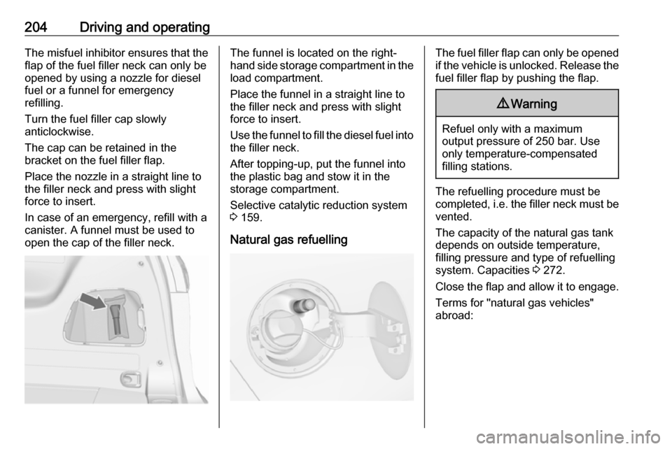
In case of an emergency, refill with a
canister. A funnel must be used to
open the cap of the filler neck.The funnel is located on the right-
hand side storage compartment in the load compartment.
Place the funnel in a straight line to
the filler neck and press with slight force to insert.
Use the funnel to fill the diesel fuel into
the filler neck.
After topping-up, put the funnel into
the plastic bag and stow it in the storage compartment.
Selective catalytic reduction system
3 159.
Natural gas refuellingThe fuel filler flap can only be opened
if the vehicle is unlocked. Release the
fuel filler flap by pushing the flap.9 Warning
Refuel only with a maximum
output pressure of 250 bar. Use
only temperature-compensated
filling stations.
The refuelling procedure must be
completed, i.e. the filler neck must be
vented.
The capacity of the natural gas tank depends on outside temperature,
filling pressure and type of refuelling
system. Capacities 3 272.
Close the flap and allow it to engage. Terms for "natural gas vehicles"
abroad:
Page 207 of 291
Driving and operating205GermanErdgasfahrzeugeEnglishNGVs = Natural Gas Vehi‐
clesFrenchVéhicules au gaz naturel -
or - Véhicules GNVItalianMetano auto
Terms for "natural gas" abroad:
GermanErdgasEnglishCNG = Compressed
Natural GasFrenchGNV = Gaz Naturel (pour)
Véhicules - or -
CGN = carburantgaz
naturelItalianMetano (per auto)
Liquid gas refuelling
Follow the operating and safety
instructions of the filling station when
refuelling.
The filling valve for the liquid gas is
behind the fuel filler cap.
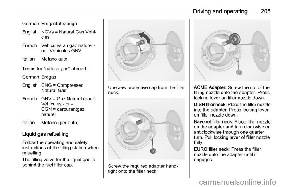
Unscrew protective cap from the filler neck.
Screw the required adapter hand-
tight onto the filler neck.
ACME Adapter: Screw the nut of the
filling nozzle onto the adapter. Press
locking lever on filler nozzle down.
DISH filler neck: Place the filler nozzle
into the adapter. Press locking lever
on filler nozzle down.
Bayonet filler neck: Place filler nozzle
on the adapter and turn clockwise or
anticlockwise through one quarter
turn. Pull locking lever of filler nozzle
fully.
EURO filler neck: Press the filler
nozzle onto the adapter until it
engages.
Page 208 of 291
206Driving and operatingPress the button at the liquid gas
supply point. The filling system stops
or begins to run slowly when 80% of
the tank volume is reached
(maximum fill level).
Release button on filling system to
stop the filling process. Release the
locking lever and remove the filler
nozzle. A small quantity of liquid gas
may escape.
Remove adapter and stow in vehicle.
Fit protective cap to prevent the
penetration of foreign bodies into the
filler opening and the system.9 Warning
Due to the system design, an
escape of liquid gas after
releasing the locking lever is
unavoidable. Avoid inhaling.
9 Warning
The liquid gas tank should only be
filled to 80% capacity, for safety
reasons.
The multivalve on the liquid gas tank
automatically limits the fill quantity. If
a larger quantity is added, we
recommend not exposing the vehicle
to the sun until the excess amount
has been used up.
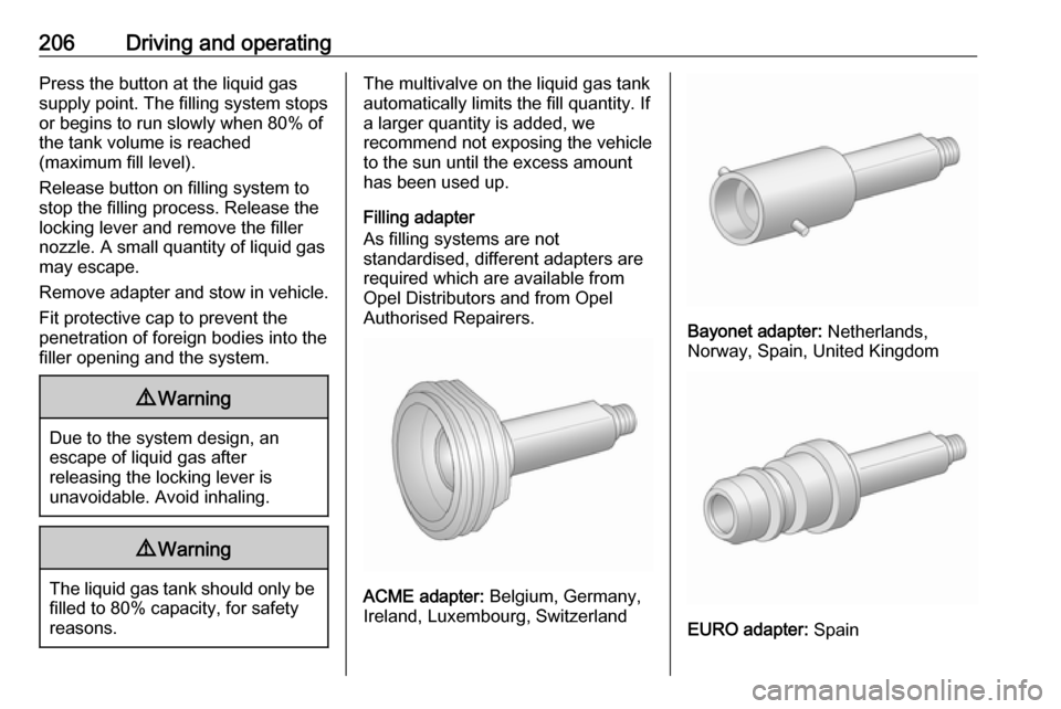
Filling adapter
As filling systems are not
standardised, different adapters are
required which are available from
Opel Distributors and from Opel
Authorised Repairers.
ACME adapter: Belgium, Germany,
Ireland, Luxembourg, Switzerland
Bayonet adapter: Netherlands,
Norway, Spain, United Kingdom
EURO adapter: Spain
Page 212 of 291
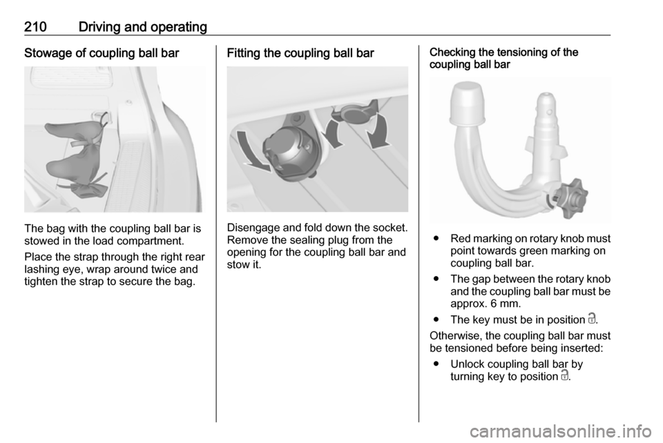
210Driving and operatingStowage of coupling ball bar
The bag with the coupling ball bar is
stowed in the load compartment.
Place the strap through the right rear lashing eye, wrap around twice and
tighten the strap to secure the bag.
Fitting the coupling ball bar
Disengage and fold down the socket. Remove the sealing plug from the
opening for the coupling ball bar and
stow it.
Checking the tensioning of the
coupling ball bar
● Red marking on rotary knob must
point towards green marking on
coupling ball bar.
● The gap between the rotary knob
and the coupling ball bar must be approx. 6 mm.
● The key must be in position c.
Otherwise, the coupling ball bar must be tensioned before being inserted:
● Unlock coupling ball bar by turning key to position c.
Page 213 of 291
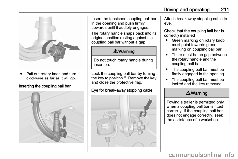
Driving and operating211
● Pull out rotary knob and turnclockwise as far as it will go.
Inserting the coupling ball bar
Insert the tensioned coupling ball bar
in the opening and push firmly
upwards until it audibly engages.
The rotary handle snaps back into its
original position resting against the
coupling ball bar without a gap.9 Warning
Do not touch rotary handle during
insertion.
Lock the coupling ball bar by turning
the key to position e. Remove the key
and close the protective flap.
Eye for break-away stopping cable
Attach breakaway stopping cable to
eye.
Check that the coupling ball bar is correctly installed
● Green marking on rotary knob must point towards green
marking on coupling ball bar.
● There must be no gap between the rotary handle and the
coupling ball bar.
● The coupling ball bar must be firmly engaged in the opening.
● The coupling ball bar must be locked and the key removed.9Warning
Towing a trailer is permitted only
when a coupling ball bar is fitted correctly. If the coupling ball bardoes not engage correctly, seekthe assistance of a workshop.
Page 214 of 291
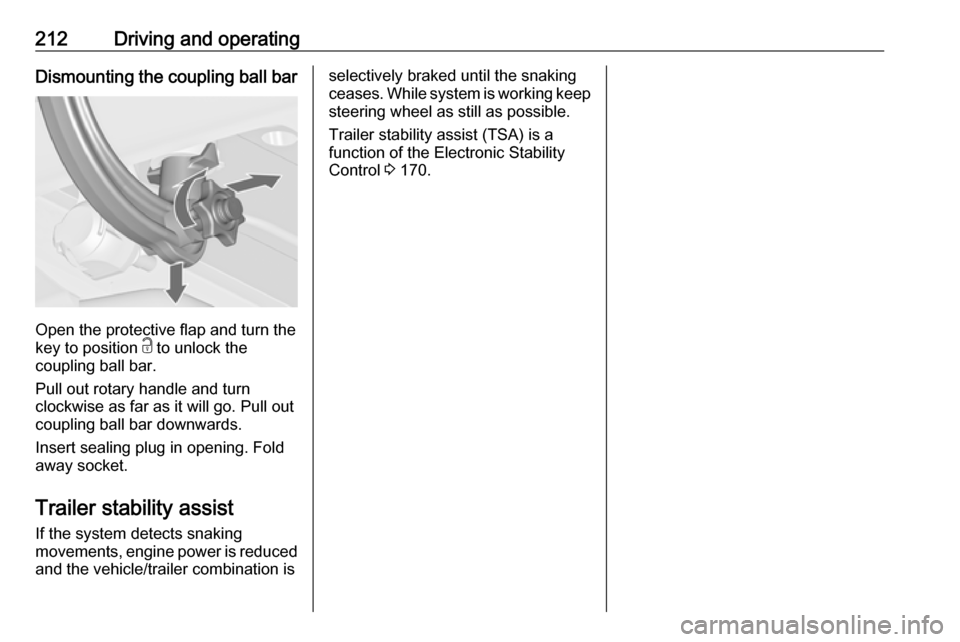
212Driving and operatingDismounting the coupling ball bar
Open the protective flap and turn the
key to position c to unlock the
coupling ball bar.
Pull out rotary handle and turn
clockwise as far as it will go. Pull out coupling ball bar downwards.
Insert sealing plug in opening. Fold away socket.
Trailer stability assist
If the system detects snaking
movements, engine power is reduced
and the vehicle/trailer combination is
selectively braked until the snaking ceases. While system is working keep steering wheel as still as possible.
Trailer stability assist (TSA) is a
function of the Electronic Stability
Control 3 170.