lock OPEL ZAFIRA C 2017.25 Owner's Guide
[x] Cancel search | Manufacturer: OPEL, Model Year: 2017.25, Model line: ZAFIRA C, Model: OPEL ZAFIRA C 2017.25Pages: 291, PDF Size: 9.02 MB
Page 68 of 291
66StorageStorageStorage compartments................66
Glovebox ................................... 66
Cupholders ................................ 66
Front storage ............................. 68
Door panel storage ....................68
Overhead console .....................68
Underseat storage .....................68
Armrest storage .........................69
Centre console storage .............69
Rear carrier system ...................70
Load compartment .......................79
Rear storage .............................. 81
Load compartment cover ...........81
Rear floor storage cover ............83
Load rails and hooks .................88
Lashing eyes ............................. 88
Cargo management system ......88
Safety net .................................. 90
Folding tray ................................ 92
Warning triangle ........................92
First aid kit ................................. 92
Roof rack system .........................93
Roof rack ................................... 93
Loading information .....................94Storage compartments9Warning
Do not store heavy or sharp
objects in the storage
compartments. Otherwise, the
storage compartment lid could
open and vehicle occupants could be injured by objects being thrown
around in the event of hard
braking, a sudden change in
direction or an accident.
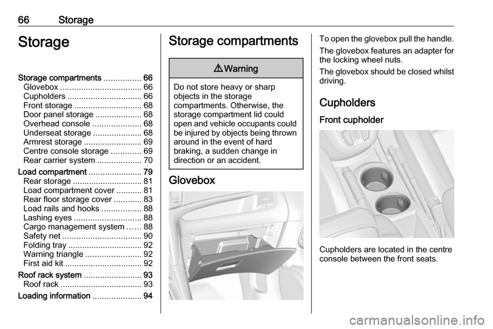
Glovebox
To open the glovebox pull the handle.
The glovebox features an adapter for the locking wheel nuts.
The glovebox should be closed whilst
driving.
Cupholders
Front cupholder
Cupholders are located in the centre
console between the front seats.
Page 74 of 291
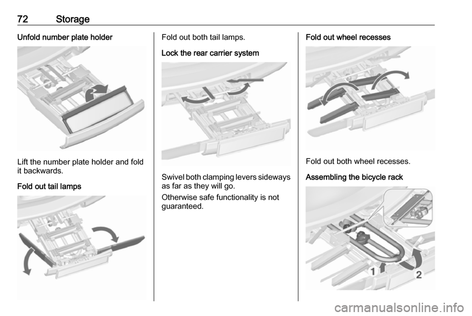
72StorageUnfold number plate holder
Lift the number plate holder and fold
it backwards.
Fold out tail lamps
Fold out both tail lamps.
Lock the rear carrier system
Swivel both clamping levers sideways as far as they will go.
Otherwise safe functionality is not
guaranteed.
Fold out wheel recesses
Fold out both wheel recesses.
Assembling the bicycle rack
Page 75 of 291
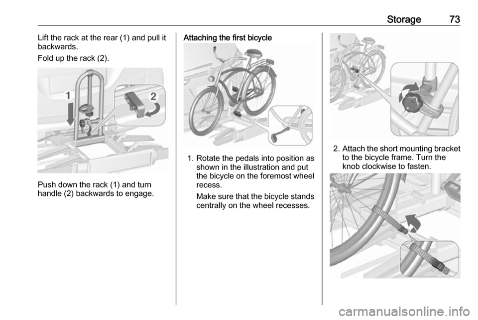
Storage73Lift the rack at the rear (1) and pull it
backwards.
Fold up the rack (2).
Push down the rack (1) and turn
handle (2) backwards to engage.
Attaching the first bicycle
1. Rotate the pedals into position as shown in the illustration and put
the bicycle on the foremost wheel
recess.
Make sure that the bicycle stands centrally on the wheel recesses.
2. Attach the short mounting bracket
to the bicycle frame. Turn the
knob clockwise to fasten.
Page 78 of 291

76Storage● Without attached adapter:
Push the lever (1) to disengage
and hold.
Pull the rack (2) backwards to
fold the rear carrier system.
● With attached adapter:
9 Warning
Take care when disengaging the
rear carrier system as it will tilt
backwards. Risk of injury.
Hold frame (1) of rearmost
bicycle with one hand and pull the
loop (2) to disengage.
Hold rearmost bicycle with both
hands and fold the rear carrier
system backwards.
To increase visibility, the tail lights of
the vehicle are activated when the
rear carrier system is folded back.
9 Warning
When folding the rear carrier
system forwards again, take care
that the system is engaged
securely.
Removing bicycles
Undo strap retainers on bicycle tyres.
Turn knob anti-clockwise and remove
mounting brackets.
Detaching adapter
Detach the adapter before removing
the last bicycle remaining on the rear
carrier system.
1. Fold in wheel recesses.
2. Unbutton the strap.
Page 80 of 291
78Storage
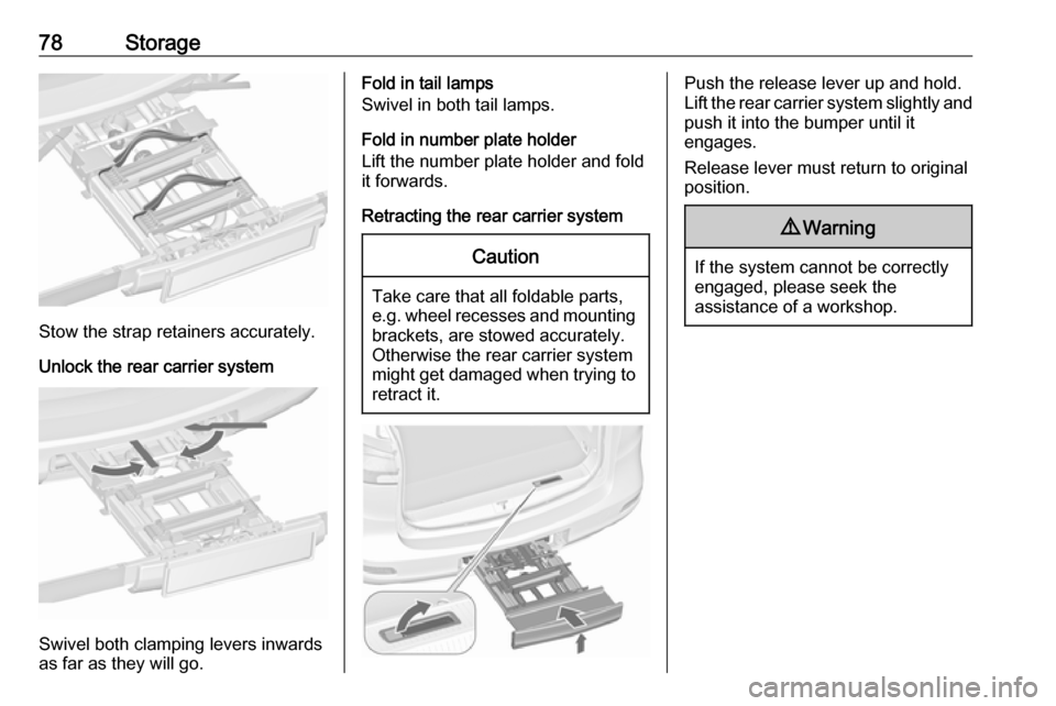
Stow the strap retainers accurately.
Unlock the rear carrier system
Swivel both clamping levers inwards
as far as they will go.
Fold in tail lamps
Swivel in both tail lamps.
Fold in number plate holder
Lift the number plate holder and fold
it forwards.
Retracting the rear carrier systemCaution
Take care that all foldable parts,
e.g. wheel recesses and mounting brackets, are stowed accurately.
Otherwise the rear carrier system might get damaged when trying to retract it.
Push the release lever up and hold.
Lift the rear carrier system slightly and
push it into the bumper until it
engages.
Release lever must return to original
position.9 Warning
If the system cannot be correctly
engaged, please seek the
assistance of a workshop.
Page 83 of 291
Storage819Warning
Only drive the vehicle if the
backrests are securely locked into position. Otherwise there is a risk
of personal injury or damage to the
load or vehicle in the event of
heavy braking or a collision.
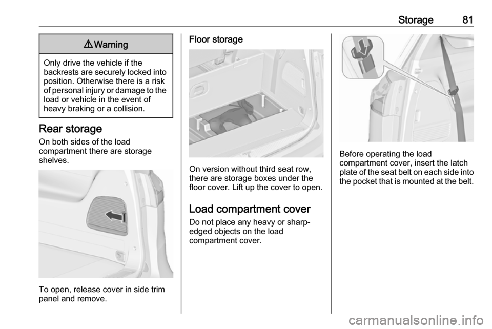
Rear storage
On both sides of the load
compartment there are storage
shelves.
To open, release cover in side trim
panel and remove.
Floor storage
On version without third seat row,
there are storage boxes under the
floor cover. Lift up the cover to open.
Load compartment cover
Do not place any heavy or sharp-
edged objects on the load
compartment cover.
Before operating the load
compartment cover, insert the latch
plate of the seat belt on each side into
the pocket that is mounted at the belt.
Page 90 of 291
88StorageLoad rails and hooks
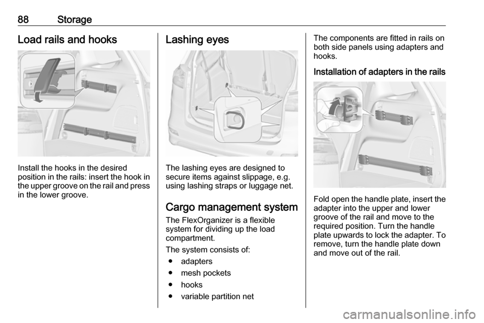
Install the hooks in the desired
position in the rails: insert the hook in the upper groove on the rail and pressin the lower groove.
Lashing eyes
The lashing eyes are designed to
secure items against slippage, e.g.
using lashing straps or luggage net.
Cargo management system The FlexOrganizer is a flexible
system for dividing up the load
compartment.
The system consists of:
● adapters
● mesh pockets
● hooks
● variable partition net
The components are fitted in rails on
both side panels using adapters and
hooks.
Installation of adapters in the rails
Fold open the handle plate, insert the adapter into the upper and lower
groove of the rail and move to the
required position. Turn the handle
plate upwards to lock the adapter. To
remove, turn the handle plate down
and move out of the rail.
Page 92 of 291
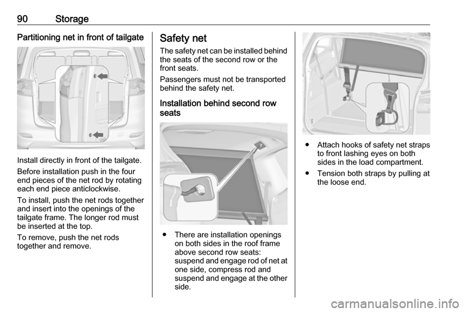
90StoragePartitioning net in front of tailgate
Install directly in front of the tailgate.
Before installation push in the four
end pieces of the net rod by rotating
each end piece anticlockwise.
To install, push the net rods together
and insert into the openings of the
tailgate frame. The longer rod must
be inserted at the top.
To remove, push the net rods
together and remove.
Safety net
The safety net can be installed behind the seats of the second row or the
front seats.
Passengers must not be transported
behind the safety net.
Installation behind second row
seats
● There are installation openings on both sides in the roof frame
above second row seats:
suspend and engage rod of net at
one side, compress rod and
suspend and engage at the other side.
● Attach hooks of safety net straps
to front lashing eyes on both
sides in the load compartment.
● Tension both straps by pulling at the loose end.
Page 98 of 291

96Instruments and controlsInstruments and
controlsControls ....................................... 97
Steering wheel adjustment ........97
Steering wheel controls .............97
Heated steering wheel ...............97
Horn ........................................... 98
Windscreen wiper/washer .........98
Rear window wiper/washer .....100
Outside temperature ................100
Clock ....................................... 101
Power outlets ........................... 102
Cigarette lighter .......................103
Ashtrays .................................. 103
Warning lights, gauges and indi‐ cators ......................................... 104
Instrument cluster ....................104
Speedometer ........................... 104
Odometer ................................ 104
Trip odometer .......................... 104
Tachometer ............................. 105
Fuel gauge .............................. 105
Fuel selector ............................ 106
Engine coolant temperature gauge ..................................... 107
Service display ........................ 107Control indicators ....................108
Turn signal ............................... 110
Seat belt reminder ...................111
Airbag and belt tensioners .......111
Airbag deactivation ..................112
Charging system .....................112
Malfunction indicator light ........112
Brake and clutch system .........112
Operate pedal .......................... 113
Electric parking brake ..............113
Electric parking brake fault ......113
Antilock brake system (ABS) ...113
Gear shifting ............................ 114
Power steering ........................ 114
Following distance ...................114
Lane departure warning ..........114
Electronic Stability Control off . 114
Electronic Stability Control and Traction Control system .........114
Traction Control system off .....114
Preheating ............................... 115
Diesel particle filter ..................115
AdBlue ..................................... 115
Tyre pressure monitoring system .................................... 115
Engine oil pressure ..................115
Low fuel ................................... 116
Immobiliser .............................. 116
Exterior light ............................ 116
High beam ............................... 116High beam assist.....................116
LED headlights ........................ 116
Fog light ................................... 116
Rear fog light ........................... 116
Cruise control .......................... 116
Adaptive cruise control ............117
Vehicle detected ahead ...........117
Speed limiter ........................... 117
Traffic sign assistant ................117
Door open ................................ 117
Information displays ...................117
Driver Information Centre ........117
Info display .............................. 121
Vehicle messages ......................123
Warning chimes .......................124
Battery voltage ........................ 124
Vehicle personalisation ..............125
Telematics service .....................128
OnStar ..................................... 128
Page 99 of 291

Instruments and controls97Controls
Steering wheel adjustment
Unlock lever, adjust steering wheel,
then engage lever and ensure it is
fully locked.
Do not adjust steering wheel unless
vehicle is stationary and steering
wheel lock has been released.
Steering wheel controls
The Infotainment system, some driver assistance systems and a connected
mobile phone can be operated via the
controls on the steering wheel.
Further information is available in the
Infotainment manual.
Driver assistance systems 3 173.
Heated steering wheel
Activate heating by pressing *.
Activation is indicated by the LED in
the button.