warning OPEL ZAFIRA C 2018.5 Manual user
[x] Cancel search | Manufacturer: OPEL, Model Year: 2018.5, Model line: ZAFIRA C, Model: OPEL ZAFIRA C 2018.5Pages: 341, PDF Size: 10.22 MB
Page 267 of 341
Vehicle care265
Batteries do not belong in household
waste. They must be disposed of at
an appropriate recycling collection
point.
Laying up the vehicle for more than
four weeks can lead to battery
discharge. Disconnect the clamp from the negative terminal of the vehicle
battery.
Ensure the ignition is switched off
before connecting or disconnecting
the vehicle battery.
Vehicle battery discharge protection
3 139.
Disconnecting the battery
If the vehicle's battery is to be
disconnected (e.g. for maintenance
work), the alarm siren must be
deactivated as follows: switch the
ignition on then off, then disconnect
the vehicle's battery within
15 seconds.
Replacing the vehicle battery Note
Any deviation from the instructions
given in this section may lead to
temporary deactivation or
disturbance of the stop-start system.
When the vehicle battery is being
replaced, please ensure that there
are no open ventilation holes in the
vicinity of the positive terminal. If a
ventilation hole is open in this area, it
must be closed off with a dummy cap, and the ventilation in the vicinity of the
negative terminal must be opened.
Only use vehicle batteries that allow the fuse box to be mounted above the
vehicle battery.
Ensure that the battery is always replaced by the same type of battery.We recommend that you have the
vehicle battery replaced by a
workshop.
Stop-start system 3 201.
Charging the vehicle battery9 Warning
On vehicles with stop-start
system, ensure that the charging potential does not exceed
14.6 volts when using a battery
charger. Otherwise the vehicle
battery might be damaged.
Jump starting 3 296.
Page 268 of 341
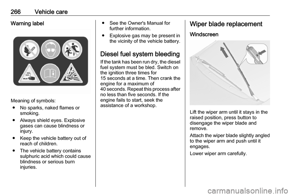
266Vehicle careWarning label
Meaning of symbols:● No sparks, naked flames or smoking.
● Always shield eyes. Explosive gases can cause blindness or
injury.
● Keep the vehicle battery out of reach of children.
● The vehicle battery contains sulphuric acid which could cause
blindness or serious burn
injuries.
● See the Owner's Manual for further information.
● Explosive gas may be present in the vicinity of the vehicle battery.
Diesel fuel system bleeding If the tank has been run dry, the diesel
fuel system must be bled. Switch on
the ignition three times for
15 seconds at a time. Then crank the
engine for a maximum of 40 seconds. Repeat this process after
no less than five seconds. If the
engine fails to start, seek the
assistance of a workshop.Wiper blade replacement
Windscreen
Lift the wiper arm until it stays in the
raised position, press button to
disengage the wiper blade and
remove.
Attach the wiper blade slightly angled
to the wiper arm and push until it
engages.
Lower wiper arm carefully.
Page 282 of 341

280Vehicle careNo.Circuit1–2Trailer outlet3Parking assist4Selective catalytic reduction
system5–6–7Power seat8–9Selective catalytic reduction
system10Nitrogen oxide sensor11Trailer module/Trailer socket12Trailer module13Trailer outlet14–15–No.Circuit16Interior mirror/Rear view
camera17Power outlet18–19–20–21Heated front seats22–23–24Selective catalytic reduction
system25–26–27–28–29–30–No.Circuit31–32Active damping system/Lane
departure warning
Page 284 of 341
282Vehicle careDirectional tyres
Fit directional tyres such that they roll in the direction of travel. The rolling
direction is indicated by a symbol
(e.g. an arrow) on the sidewall.
Tyre pressure
Check the pressure of cold tyres at least every 14 days and before any
long journey. Do not forget the spare
wheel. This also applies to vehicles
with tyre pressure monitoring system.
Tyre pressure 3 319.
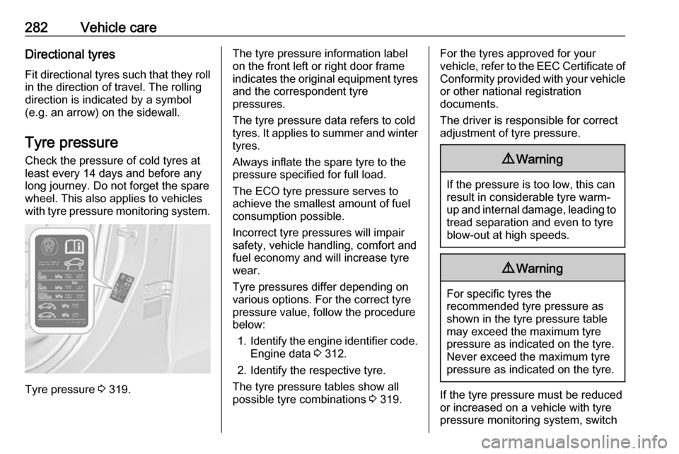
The tyre pressure information label
on the front left or right door frame
indicates the original equipment tyres
and the correspondent tyre
pressures.
The tyre pressure data refers to cold
tyres. It applies to summer and winter tyres.
Always inflate the spare tyre to the
pressure specified for full load.
The ECO tyre pressure serves to
achieve the smallest amount of fuel
consumption possible.
Incorrect tyre pressures will impair
safety, vehicle handling, comfort and
fuel economy and will increase tyre
wear.
Tyre pressures differ depending on
various options. For the correct tyre
pressure value, follow the procedure
below:
1. Identify the engine identifier code.
Engine data 3 312.
2. Identify the respective tyre.
The tyre pressure tables show all possible tyre combinations 3 319.For the tyres approved for your
vehicle, refer to the EEC Certificate of
Conformity provided with your vehicle
or other national registration
documents.
The driver is responsible for correct
adjustment of tyre pressure.9 Warning
If the pressure is too low, this can
result in considerable tyre warm-
up and internal damage, leading to tread separation and even to tyre
blow-out at high speeds.
9 Warning
For specific tyres the
recommended tyre pressure as
shown in the tyre pressure table may exceed the maximum tyre
pressure as indicated on the tyre.
Never exceed the maximum tyre
pressure as indicated on the tyre.
If the tyre pressure must be reduced
or increased on a vehicle with tyre
pressure monitoring system, switch
Page 286 of 341
284Vehicle careSelect Tyre pressure page under
Vehicle Information Menu ?
3 117.
System status and pressure warnings are displayed by a message
indicating the corresponding tyre in the Driver Information Centre.
The system considers the tyre
temperature for the warnings.
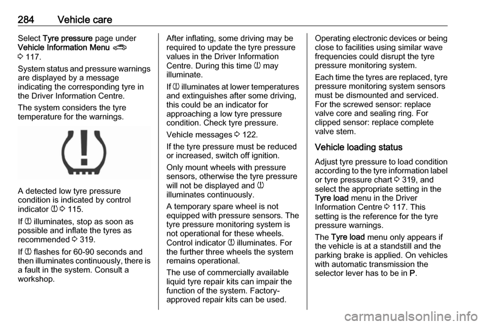
A detected low tyre pressure
condition is indicated by control
indicator w 3 115.
If w illuminates, stop as soon as
possible and inflate the tyres as
recommended 3 319.
If w flashes for 60-90 seconds and
then illuminates continuously, there is
a fault in the system. Consult a
workshop.
After inflating, some driving may be
required to update the tyre pressure
values in the Driver Information
Centre. During this time w may
illuminate.
If w illuminates at lower temperatures
and extinguishes after some driving,
this could be an indicator for
approaching a low tyre pressure
condition. Check tyre pressure.
Vehicle messages 3 122.
If the tyre pressure must be reduced
or increased, switch off ignition.
Only mount wheels with pressure
sensors, otherwise the tyre pressure
will not be displayed and w
illuminates continuously.
A temporary spare wheel is not
equipped with pressure sensors. The
tyre pressure monitoring system is
not operational for these wheels.
Control indicator w illuminates. For
the further three wheels the system
remains operational.
The use of commercially available
liquid tyre repair kits can impair the
function of the system. Factory-
approved repair kits can be used.Operating electronic devices or being close to facilities using similar wave
frequencies could disrupt the tyre
pressure monitoring system.
Each time the tyres are replaced, tyre pressure monitoring system sensors
must be dismounted and serviced. For the screwed sensor: replace
valve core and sealing ring. For
clipped sensor: replace complete
valve stem.
Vehicle loading status Adjust tyre pressure to load condition
according to the tyre information label or tyre pressure chart 3 319, and
select the appropriate setting in the Tyre load menu in the Driver
Information Centre 3 117. This
setting is the reference for the tyre
pressure warnings.
The Tyre load menu only appears if
the vehicle is at a standstill and the parking brake is applied. On vehicles
with automatic transmission the
selector lever has to be in P.
Page 287 of 341

Vehicle care285
Select Tyre load page under Vehicle
Information Menu ? in the Driver
Information Centre 3 117.
Select: ● Light for comfort pressure up to
3 people.
● Eco for Eco pressure up to
3 people.
● Max for full load.
Tyre pressure sensor matching
process
Each tyre pressure sensor has a
unique identification code. The
identification code must be matched
to a new wheel position after rotating
the wheels or exchanging the
complete wheel set and if one or more
tyre pressure sensors were replaced. The tyre pressure sensor matching
process should also be performed
after replacing a spare wheel with a
road wheel containing the tyre
pressure sensor.
The malfunction light w and the
warning message or code should
extinguish at the next ignition cycle.
The sensors are matched to the
wheel positions, using a relearn tool,
in the following order: left side front
wheel, right side front wheel, right
side rear wheel and left side rear
wheel. The turn signal light at the
current active position is illuminated
until sensor is matched.
Consult your workshop for service.
There are two minutes to match the
first wheel position, and five minutes
overall to match all four wheel
positions. If it takes longer, the
matching process stops and must be
restarted.
The tyre pressure sensor matching
process is:
1. Apply the parking brake.2. Turn the ignition on.
3. On vehicles with automatic transmission: set the selector
lever to P.
On vehicles with manual
transmission: select neutral.
4. Press MENU on the turn signal
lever to select the Vehicle
Information Menu ? in the
Driver Information Centre.
5. Turn the adjuster wheel to scroll to
the tyre pressure menu.
Page 289 of 341

Vehicle care287Changing tyre and wheelsize
If tyres of a different size than those
fitted at the factory are used, it may be necessary to reprogramme the
nominal tyre pressure and make
other vehicle modifications.
After converting to a different tyre
size, have the label with tyre
pressures replaced. 3 2839 Warning
The use of unsuitable tyres or
wheels may lead to accidents and will invalidate the vehicle
operating permit.
Wheel covers
Wheel covers and tyres that are
factory approved for the respective
vehicle and comply with all of the
relevant wheel and tyre combination
requirements must be used.
If the wheel covers and tyres used are
not factory approved, the tyres must
not have a rim protection ridge.
Wheel covers must not impair brake
cooling.9 Warning
Use of unsuitable tyres or wheel
covers could lead to sudden
pressure loss and thereby
accidents.
Vehicles with steel wheels: When
using locking wheel nuts, do not
attach wheel covers.
Tyre chains
Tyre chains are only permitted on the
front wheels.
Always use fine mesh chains that add no more than 10 mm to the tyre tread
and the inboard sides (including chain lock).9 Warning
Damage may lead to tyre blowout.
Tyre chains are only permitted on
tyres of size 215/60 R16 and
225/50 R17.
The use of tyre chains is not permitted on the temporary spare wheel.
Tyre repair kit
Minor damage to the tyre tread can be
repaired with the tyre repair kit.
Do not remove foreign bodies from
the tyres.
Tyre damage exceeding 4 mm or that
is at the tyre's sidewall cannot be
repaired with the tyre repair kit.
Page 290 of 341

288Vehicle care9Warning
Do not drive faster than 80 km/h.
Do not use for a lengthy period.
Steering and handling may be
affected.
If you have a flat tyre:
Apply the parking brake and engage
first gear, reverse gear or P.
The tyre repair kit is on the left side in
the load compartment behind a cover.
1. Take the tyre repair kit from the compartment.
2. Remove the compressor.
3. Remove the electrical connection cable and air hose from the
stowage compartments on the
underside of the compressor.
4. Screw the compressor air hose to
the connection on the sealant
bottle.
5. Fit the sealant bottle into the retainer on the compressor.
Set the compressor near the tyre
in such a way that the sealant
bottle is upright.
6. Unscrew valve cap from defective
tyre.
7. Screw the filler hose to the tyre valve.
8. The switch on the compressor must be set to J.
Page 293 of 341
Vehicle care291●Do not start the vehicle when it is
raised on the jack.
● Clean wheel nuts and thread with
a clean cloth before mounting the
wheel.9 Warning
Do not grease wheel bolt, wheel
nut and wheel nut cone.
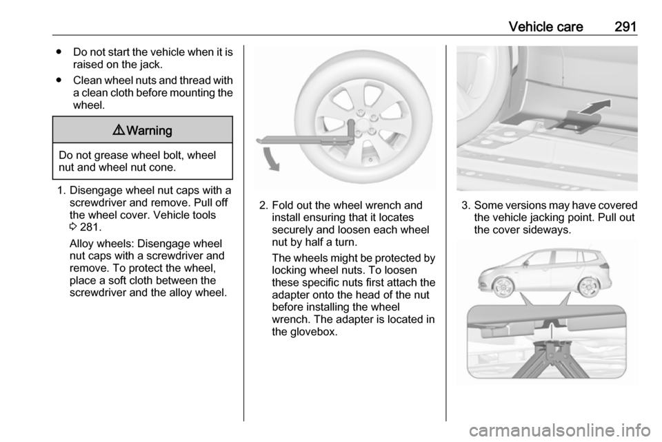
1. Disengage wheel nut caps with a
screwdriver and remove. Pull off
the wheel cover. Vehicle tools
3 281.
Alloy wheels: Disengage wheel
nut caps with a screwdriver and
remove. To protect the wheel,
place a soft cloth between the
screwdriver and the alloy wheel.
2. Fold out the wheel wrench and install ensuring that it locates
securely and loosen each wheel
nut by half a turn.
The wheels might be protected by
locking wheel nuts. To loosen
these specific nuts first attach the
adapter onto the head of the nut
before installing the wheel
wrench. The adapter is located in
the glovebox.3. Some versions may have covered
the vehicle jacking point. Pull out
the cover sideways.
Page 297 of 341
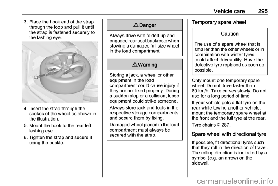
Vehicle care2953. Place the hook end of the strapthrough the loop and pull it until
the strap is fastened securely to
the lashing eye.
4. Insert the strap through the spokes of the wheel as shown in
the illustration.
5. Mount the hook to the rear left lashing eye.
6. Tighten the strap and secure it using the buckle.
9 Danger
Always drive with folded up and
engaged rear seat backrests when stowing a damaged full size wheel
in the load compartment.
9 Warning
Storing a jack, a wheel or other
equipment in the load
compartment could cause injury if they are not fixed properly. During a sudden stop or a collision, looseequipment could strike someone.
Always store jack and tools in the
respective storage compartments
and secure them by fixing.
Damaged wheel placed in the load
compartment must always be
secured with the strap.
Temporary spare wheelCaution
The use of a spare wheel that is smaller than the other wheels or in combination with winter tyres
could affect driveability. Have the defective tyre replaced as soon as
possible.
Only mount one temporary spare
wheel. Do not drive faster than
80 km/h. Take curves slowly. Do not use for a long period of time.
If your vehicle gets a flat tyre on the
rear while towing another vehicle,
mount the temporary spare wheel at
the front and the full tyre at the rear.
Tyre chains 3 287.
Spare wheel with directional tyre
If possible, fit directional tyres such
that they roll in the direction of travel.
The rolling direction is indicated by a
symbol (e.g. an arrow) on the
sidewall.