ECU PEUGEOT 2008 2016 Service Manual
[x] Cancel search | Manufacturer: PEUGEOT, Model Year: 2016, Model line: 2008, Model: PEUGEOT 2008 2016Pages: 450, PDF Size: 14.16 MB
Page 186 of 450

184
2008_en_Chap09_info-pratiques_ed01-2016
Repair procedure
F Uncoil the pipe stowed under the compressor.
F
C
onnect the pipe from the compressor to
the sealant cartridge.
F
T
urn the sealant cartridge and secure it in
the cut-out provided on the compressor. F
R emove the valve cap from the tyre to be
repaired, and place it in a clean area.
F
C
onnect the hose from the sealant
cartridge to the valve of the tyre to be
repaired and tighten firmly.
Avoid removing any foreign bodies
which have penetrated into the tyre.
F
S
witch off the ignition.
F
S
ecure the speed limit sticker inside
the
vehicle.
Practical information
Page 196 of 450

194
2008_en_Chap09_info-pratiques_ed01-2016
Changing a wheel
The tools are installed in the boot under the
f l o o r.
To gain access to them:
F
o
pen the boot,
F
l
ift the floor and remove it,
F
r
emove the polystyrene spacer,
F
r
emove the carrier box containing the tools.
Access to the tools
List of tools*
All of these tools are specific to your
vehicle and can vary according to the level
of equipment. Do not use them for other
purposes.
1.
Wheelbrace.
F
or removing the wheel trim and removing
the wheel bolts.
2.
J
ack with integral handle.
F
or raising the vehicle.
Procedure for changing a wheel for the spare wheel using the tools provided with the vehicle.
* Depending on the country of sale. 3.
"
Bolt cover" tool.
F
or removing the bolt protectors (covers)
on alloy wheels.
4.
S
ocket for the security bolts (located in the
glove box).
F
or adapting the wheelbrace to the special
"security" bolts.
5.
R
emovable towing eye.
For more information on the removable towing
eye, refer to the corresponding section.
Practical information
Page 197 of 450

195
2008_en_Chap09_info-pratiques_ed01-2016
The spare wheel is installed in the boot under
t h e f l o o r.
The spare wheel is a steel wheel or a space-
saver wheel, depending on the country of sale.
It is secured by a nut A and a screw B. For the
nut, proceed as follows.
Access to the spare wheel*
Taking out the wheel
F Unscrew the central (coloured) nut.
F R aise the spare wheel towards you from
the rear.
F
T
ake the wheel out of the boot.
* Depending on the country of sale.
Wheel with wheel trim
When refitting the wheel , refit the
wheel trim starting by placing its cut-out
facing the valve and press around its
edge with the palm of your hand.
9
Practical information
Page 199 of 450

197
2008_en_Chap09_info-pratiques_ed01-2016
F Place the foot of the jack 2 on the ground and ensure that it is directly below the
front
A or rear B jacking point provided on
the underbody, whichever is closest to the
wheel to be changed.
Removing a wheel
Parking the vehicle
Immobilise the vehicle where it does not
block traffic: the ground must be level,
stable and not slippery.
Apply the parking brake.
Switch off the ignition.
With a manual gearbox, engage first
gear to block the wheels.
With an electronic gearbox, place the
gear selector at position R to block the
wheels.
With an automatic gearbox, place the
gear selector at position P to block the
wheels.
Check that the parking brake warning
lamps in the instrument panel come on.
The occupants must get out of the
vehicle and wait where they are safe.
Never go underneath a vehicle raised
using a jack; use an axle stand.
List of operations
F Remove the bolt cover from each of the bolts using the tool 3 (according to
equipment).
F
F
it the security socket 4 on the
wheelbrace
1 to slacken the security bolt
(if fitted).
F
S
lacken the other bolts using the
wheelbrace 1 o n l y.
Never use:
-
t
he jack for any other purpose than
raising the vehicle,
-
a j
ack other than the one provided
by the manufacturer.
9
Practical information
Page 201 of 450

199
2008_en_Chap09_info-pratiques_ed01-2016
Fitting a wheel
Fitting the "space-saver"
spare wheel
If your vehicle is fitted with alloy wheels,
when tightening the bolts on fitting, it
is normal to notice that the washers do
not come into contact with the "space-
saver" spare wheel. The wheel is
secured by the conical shoulder of each
bolt (see drawing).
When refitting the alloy wheel, ensure
that the wheel bolt washers are clean
and in good condition.
After changing a wheel
To store the punctured wheel in the
boot correctly, first remove the central
c ove r.
When using the "space-saver" type
spare wheel, do not exceed 50 mph
(80 km/h).
Have the tightening of the bolts and the
pressure of the spare wheel checked
by a PEUGEOT dealer or a qualified
workshop without delay.
Have the punctured wheel repaired
and refitted to the vehicle as soon as
possible.
9
Practical information
Page 202 of 450

200
2008_en_Chap09_info-pratiques_ed01-2016
List of operations
F Put the wheel in place on the hub.
F S crew in the bolts fully by hand.
F
P
re-tighten the security bolt using the
wheelbrace 1 fitted with the security
socket
4 (if your vehicle has them).
F
P
re-tighten the other bolts using the
wheelbrace 1 o n l y. F
L ower the vehicle fully.
F F old the jack 2 and detach it.F
T ighten the security bolt using the
wheelbrace 1 fitted with the security
socket
4 (if your vehicle has them).
F
T
ighten the other bolts using the
wheelbrace 1 o n l y.
F
R
efit the bolt covers on each of the bolts
(according to equipment).
F
S
tore the tools in the carrier box.
Practical information
Page 217 of 450
215
2008_en_Chap09_info-pratiques_ed01-2016
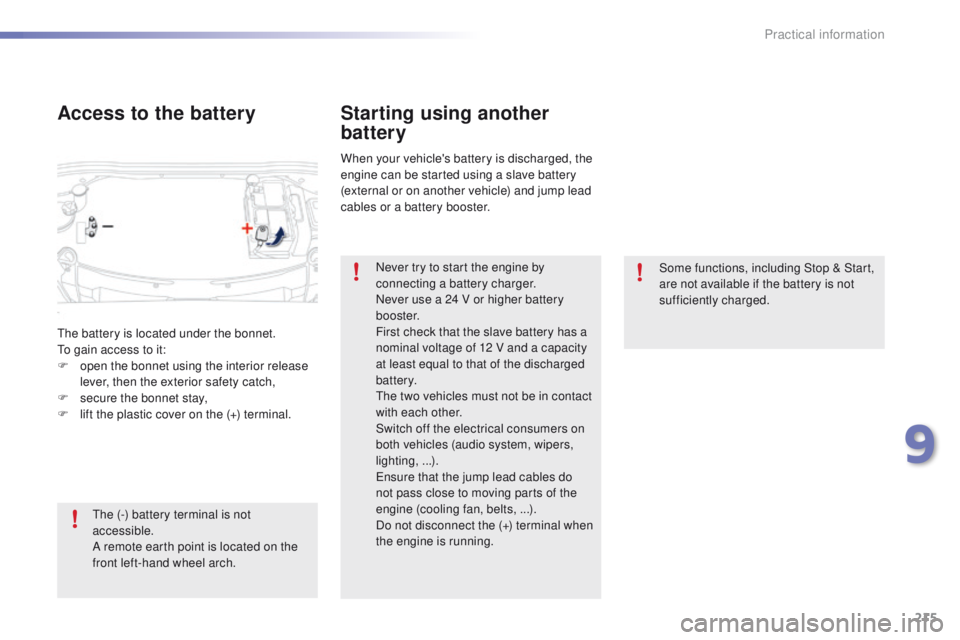
Some functions, including Stop & Start,
are not available if the battery is not
sufficiently charged.
Starting using another
battery
When your vehicle's battery is discharged, the
engine can be started using a slave battery
(external or on another vehicle) and jump lead
cables or a battery booster.Never try to start the engine by
connecting a battery charger.
Never use a 24 V or higher battery
b o o s t e r.
First check that the slave battery has a
nominal voltage of 12 V and a capacity
at least equal to that of the discharged
battery.
The two vehicles must not be in contact
with each other.
Switch off the electrical consumers on
both vehicles (audio system, wipers,
lighting, ...).
Ensure that the jump lead cables do
not pass close to moving parts of the
engine (cooling fan, belts, ...).
Do not disconnect the (+) terminal when
the engine is running.
The battery is located under the bonnet.
To gain access to it:
F
o
pen the bonnet using the interior release
lever, then the exterior safety catch,
F
s
ecure the bonnet stay,
F
l
ift the plastic cover on the (+) terminal.
Access to the battery
The (-) battery terminal is not
accessible.
A remote earth point is located on the
front left-hand wheel arch.
9
Practical information
Page 227 of 450

225
2008_en_Chap09_info-pratiques_ed01-2016
Towbar with quickly detachable towball
Presentation
This towbar allows the towball to be fitted and
removed quickly and easily without the use
of tools. Installed behind the rear bumper, the
towbar is invisible after removing the towball
and folding the trailer harness socket carrier.
1.
Carrier.
2.
P
rotective blanking plug.
3.
S
ecurity ring.
4.
F
olding trailer harness socket.
5.
D
etachable towball.
6.
L
ocking / unlocking wheel.
7.
Sec
urity key lock.
8.
Ba
ll protector.
9.
St
orage bag.
A. Locked position
The locking wheel is not in contact with the
towball (gap of about 5 mm).
The green mark is visible.
The lock for the locking wheel is facing
rearward.
The bolt is visible and extends beyond the
towball.
B. Unlocked position
The locking wheel is in contact with the towball.
The green mark is hidden.
The lock for the locking wheel is facing for ward.
The peg is not visible. Observe the legislation in force in the
country in which you are driving.
For more information on the technical
characteristics of the towbar (its
maximum load, ...), refer to the
corresponding section.
For information on safely towing a
trailer, refer to the corresponding
section.
9
Practical information
Page 228 of 450

226
2008_en_Chap09_info-pratiques_ed01-2016
Fitting the towball
Remove the protective blanking plug from the
carrier and check the condition of the fixing
system. If necessary, clean the carrier with a
brush or clean cloth.
Take the towball from the storage bag.
Remove the protective cover from the ball.
Stow the plug and cover in the storage bag.
Check that the towball is unlocked (position B).
If not, insert the key in the lock and turn the
key clockwise to unlock the mechanism.
Then press the locking wheel and turn it fully
clockwise.
Before each use
Check that the towball is correctly fitted by
verifying the following points:
-
t
he towball is correctly locked in place
(position A ),
-
t
he security key lock is on and the key
removed; the locking wheel can no
longer be operated,
-
t
he towball must no longer move at all in
its carrier; try to shake it by hand.
During use
Never unlock the towball when a trailer or
load carrier is fitted.
Never exceed the maximum authorised
weight for the vehicle plus trailer (Gross
Train Weight - GTW).
Before driving, check the adjustment of the
headlamp beam height.
For more information on adjusting the
headlamps, refer to the corresponding
section.
After use
For journeys made without a trailer or load
carrier, the trailer harness socket must be
folded away, the towball removed and
the
protective blanking plug inserted in the
carrier. This measure applies particularly
if the towball could hinder visibility of the
number plate or lighting.
Practical information
Page 229 of 450

227
2008_en_Chap09_info-pratiques_ed01-2016
Take the towball in both hands; insert the end
of the towball into the carrier, then, to ensure
that it has correctly locked in place, pull firmly
down on the ball end of the towball.
The locking wheel automatically turns a quarter
of a turn anti-clockwise, making a perceptible
click; take care to keep your hands clear.Check that the towball has correctly locked in
place (position A
).
Turn the key anti-clockwise to lock the towball
fixing mechanism.
Always remove the key and keep it in a safe
place.
If the key cannot be turned or removed, this
means that the towball is not fitted correctly;
start the procedure again.
If one of the locking conditions is not met, start
the procedure again.
In all cases, if the marking remains red, do not
use the towbar and contact a PEUGEOT dealer
or a qualified workshop. Attach the trailer to the towball.
Attach the cable on the trailer to the security
ring located on the carrier.
Lower the trailer harness socket carrier by
pulling down on the ring visible below the
b u m p e r.
Remove the protective cover from the socket
and connect the trailer wiring harness.
9
Practical information