fuse box Peugeot 306 Break Dag 2002 Owner's Manual
[x] Cancel search | Manufacturer: PEUGEOT, Model Year: 2002, Model line: 306 Break Dag, Model: Peugeot 306 Break Dag 2002Pages: 127, PDF Size: 2.17 MB
Page 2 of 127

YOUR 306 AT A GLANCE3
1
- Adjustable side vent.
2 - Side window demisting vents.
3 - Lighting control, fog lamps*
and horn.
4 - Steering wheel with airbag*.
5 - Windscreen demisting vents.
6 - Steering lock and ignition.
7 - Windscreen wash-wipe
control.
8 - Adjustable central vents.
9 - Audio equipment*. 10
- Heating/Ventilation,
Air conditioning controls*.
11 - Controls:
Lighter Hazard warning lightsRear screen and mirrors demisting.
12 - Passenger airbag*.
13 - Glove box
14 - Storage compartment.
15 - Ashtray.
16 - Gear lever.
17 - Handbrake. 18
- Audio remote control*.
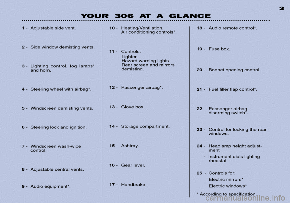
19 - Fuse box.
20 - Bonnet opening control.
21 - Fuel filler flap control*.
22 - Passenger airbag
disarming switch*.
23 - Control for locking the rear
windows.
24 - Headlamp height adjust-
ment
- Instrument dials lighting rheostat
25 - Controls for:
Electric mirrors* Electric windows*
* According to specification.
Page 106 of 127

MAINTENANCE OF YOUR 30639
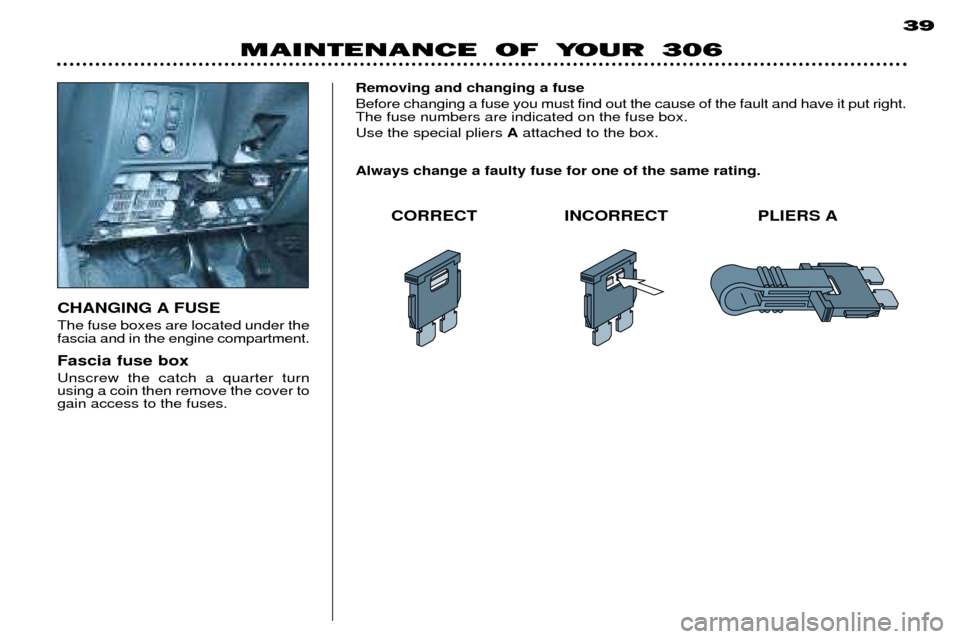
CHANGING A FUSE The fuse boxes are located under the fascia and in the engine compartment. Fascia fuse box Unscrew the catch a quarter turn using a coin then remove the cover togain access to the fuses.Removing and changing a fuse Before changing a fuse you must find out the cause of the fault and have it put right. The fuse numbers are indicated on the fuse box. Use the special pliers
Aattached to the box.
Always change a faulty fuse for one of the same rating.
CORRECT INCORRECT PLIERS A
Page 107 of 127

MAINTENANCE OF YOUR 306
42
The electrical system of your vehicle is designedto operate with standardor optional equipment.
Before installing other electricalequipment or accessories on yourvehicle, contact a PEUGEOT
dealer. Some electrical accessories or the way in which they are fitted canhave damaging effects on the ope-ration of your vehicle; the electroniccontrol circuits, the audio circuitand the battery charging circuit. PEUGEOT will not accept respon- sibility for the cost incurred in repai-ring your vehicle or for rectifyingthe malfunctions resulting from theinstallation of accessories not sup-plied and not recommended byPEUGEOT and not installed inaccordance with its instructions, inparticular where the equipment inquestion consumes more than 10milliamperes. ** The maxi-fuses provide addi- tional protection for the electrical
systems. All work must be carried
out by a PEUGEOT dealer.
* According to specification.
ENGINE COMPARTMENT FUSES*
To access the fuse box in the enginecompartment (beside the battery),
unclip the cover. Carefully close the cover when you have finished.
Fuse No. Rating* Functions* 1** 40A Anti-theft supply
2** 60A Supply to Locks - lighting switch Ð air conditioning blower unit Ð front fog relay Ð diagnostic connector
3** 60A ABS ECU supply
4** 60A + positive fuse box supply
Page 109 of 127

MAINTENANCE OF YOUR 30639
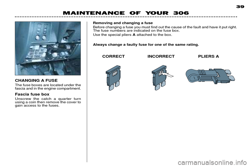
CHANGING A FUSE The fuse boxes are located under the fascia and in the engine compartment. Fascia fuse box Unscrew the catch a quarter turn using a coin then remove the cover togain access to the fuses.Removing and changing a fuse Before changing a fuse you must find out the cause of the fault and have it put right. The fuse numbers are indicated on the fuse box. Use the special pliers
Aattached to the box.
Always change a faulty fuse for one of the same rating.
CORRECT INCORRECT PLIERS A
Page 110 of 127

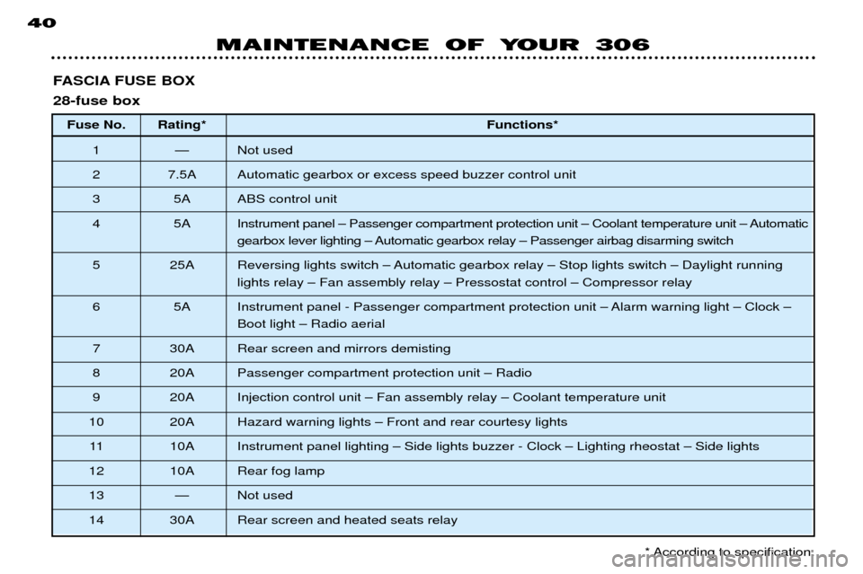
FASCIA FUSE BOX 28-fuse boxFuse No. Rating* Functions*
1 Ñ Not used
2 7.5A Automatic gearbox or excess speed buzzer control unit
3 5A ABS control unit
4 5A Instrument panel Ð Passenger compartment protection unit Ð Coolant temperature unit Ð Automatic gearbox lever lighting Ð Automatic gearbox relay Ð Passenger airbag disarming switch
5 25A Reversing lights switch Ð Automatic gearbox relay Ð Stop lights switch Ð Daylight running lights relay Ð Fan assembly relay Ð Pressostat control Ð Compressor relay
6 5A Instrument panel - Passenger compartment protection unit Ð Alarm warning light Ð Clock Ð Boot light Ð Radio aerial
7 30A Rear screen and mirrors demisting
8 20A Passenger compartment protection unit Ð Radio
9 20A Injection control unit Ð Fan assembly relay Ð Coolant temperature unit
10 20A Hazard warning lights Ð Front and rear courtesy lights 11 10A Instrument panel lighting Ð Side lights buzzer - Clock Ð Lighting rheostat Ð Side lights
12 10A Rear fog lamp
13 Ñ Not used
14 30A Rear screen and heated seats relay
MAINTENANCE OF YOUR 306
40
* According to specification.