brake Peugeot 308 2018 Workshop Manual
[x] Cancel search | Manufacturer: PEUGEOT, Model Year: 2018, Model line: 308, Model: Peugeot 308 2018Pages: 324, PDF Size: 10.72 MB
Page 175 of 324
173
Snow chains
In wintry conditions, snow chains improve
traction as well as the behaviour of the vehicle
when braking.Snow chains must be fitted only to the
front wheels. They must never be fitted to
"space-saver" type spare wheels.
Take account of the legislation in force in
your country on the use of snow chains
and the maximum authorised speed.
Installation advice
F If you have to fit the chains during a journey, stop the vehicle on a flat sur face on the side
of the road.
F
A
pply the parking brake and, if necessary,
place a chock under a wheel to prevent
movement of your vehicle.
F
F
it the chains following the instructions
provided by the manufacturer.
F
M
ove off gently and drive for a few
moments, without exceeding 31
mph
(50
km/h).
F
S
top your vehicle and check that the snow
chains are correctly tightened. It is strongly recommended that before
you leave, you practise fitting the snow
chains on a level and dry sur face.
Avoid driving with snow chains on roads
that have been cleared of snow to avoid
damaging your vehicle's tyres and the
road sur face. If your vehicle is fitted with
alloy wheels, check that no part of the
chain or its fixings is in contact with the
wheel rim.
Use only the chains designed to be fitted to the
type of wheel fitted to your vehicle:
Original tyre size Type of chain
195/65 R15 9
mm link
205/55 R16
2 2 5 /4 5 R17
225/40 R18 K-Summit K23
235/35 R19 Polar Grip 70
For more information, contact a PEUGEOT
dealer or a qualified workshop.
Very cold climate screen
Removable protective screen which prevents
the accumulation of snow at the radiator
cooling fan.
It is recommended that the screen be
fitted and removed by a PEUGEOT dealer
or a qualified workshop.
Before fitting or removing a screen,
ensure that the engine is off and the
cooling fan has stopped.
Fitting
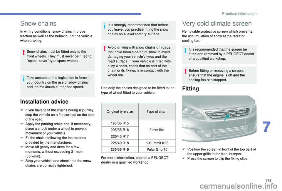
F Position the screen in front of the top part of the upper grille in the front bumper.
F
P
ress the screen to clip the fixing clips.
7
Practical information
Page 186 of 324
184
1.Screenwash fluid reservoir.
2. Engine coolant reservoir.
3. Brake fluid reser voir.
4. Battery/Fuses.
5. Fusebox.
6. A i r f i l t e r.
7. Engine oil dipstick.
8. Engine oil filler cap.
9. Remote earth point.
10. Priming pump*
The Diesel circuit is under very high
pressure.
All work on this circuit must be carried out
only by a PEUGEOT dealer or a qualified
workshop.
*
D
epending on engine.
Checking levels
Check all of these levels regularly, in line with
the manufacturer's service schedule. Top them
up if necessary, unless other wise indicated.
If a level drops significantly, have the
corresponding system checked by a PEUGEOT
dealer or a qualified workshop. The liquid must comply with the
manufacturer's recommendations and with
the vehicle's engine.
Take care when working under the bonnet,
as certain areas of the engine may be
extremely hot (risk of burns) and the
cooling fan could start at any time (even
with the ignition off).
Used products
Avoid prolonged contact of used oil or
fluids with the skin.
Most of these fluids are harmful to health
or indeed very corrosive.
Do not discard used oil or fluids into
sewers or onto the ground.
Take used oil to a PEUGEOT dealer or
a qualified workshop and dispose of it in
the containers reser ved for this purpose.
Engine oil level
The check is carried out either when
the ignition is switched on using the oil
level indicator in the instrument panel
for vehicles equipped with an electric
gauge, or using the dipstick.
To ensure that the reading is correct, your
vehicle must be parked on a level sur face
with the engine stopped for more than
30
minutes.
It is normal to top up the oil level between
two ser vices (or oil changes). PEUGEOT
recommends that you check the level, and top
up if necessary, every 3,000
miles (5,000 km).
Checking using the dipstick
The location of the dipstick is shown in the
corresponding underbonnet layout view.
F
T
ake the dipstick by its coloured grip and
pull it out completely.
F
W
ipe the end of the dipstick using a clean
non-fluffy cloth.
F
R
efit the dipstick and push fully down, then
pull it out again to make the visual check:
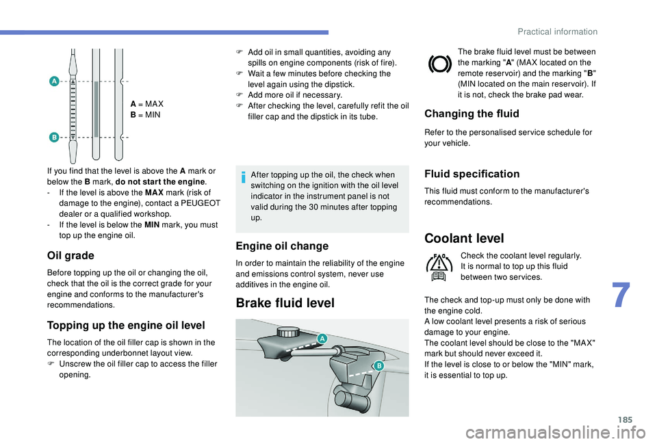
the correct level is between marks A and B .
Practical information
Page 187 of 324
185
A = MA X
B = MIN
If you find that the level is above the A mark or
below the B mark, do not star t the engine .
-
I
f the level is above the MAX mark (risk of
damage to the engine), contact a PEUGEOT
dealer or a qualified workshop.
-
I
f the level is below the MIN mark, you must
top up the engine oil.
Oil grade
Before topping up the oil or changing the oil,
check that the oil is the correct grade for your
engine and conforms to the manufacturer's
recommendations.
The location of the oil filler cap is shown in the
corresponding underbonnet layout view.
F
U
nscrew the oil filler cap to access the filler
opening.
Topping up the engine oil level
After topping up the oil, the check when
switching on the ignition with the oil level
indicator in the instrument panel is not
valid during the 30
minutes after topping
up.
Engine oil change
In order to maintain the reliability of the engine
and emissions control system, never use
additives in the engine oil.
Brake fluid level
The brake fluid level must be between
the marking " A" (MA X located on the
remote reservoir) and the marking " B"
(MIN located on the main reser voir). If
it is not, check the brake pad wear.
Changing the fluid
Refer to the personalised ser vice schedule for
your vehicle.
Fluid specification
This fluid must conform to the manufacturer's
recommendations.
Coolant level
Check the coolant level regularly.
It is normal to top up this fluid
between two services.
The check and top-up must only be done with
the engine cold.
A low coolant level presents a risk of serious
damage to your engine.
The coolant level should be close to the "MA X"
mark but should never exceed it.
If the level is close to or below the "MIN" mark,
it is essential to top up.
F
A
dd oil in small quantities, avoiding any
spills on engine components (risk of fire).
F
W
ait a few minutes before checking the
level again using the dipstick.
F
A
dd more oil if necessary.
F
A
fter checking the level, carefully refit the oil
filler cap and the dipstick in its tube.
7
Practical information
Page 189 of 324
187
Passenger compartment filter
Depending on the environment
(e.g. dusty atmosphere) and the
use of the vehicle (e.g. city driving),
replace it twice as often if
necessary.
A clogged passenger compartment
filter may have an adverse effect on
the per formance of the air conditioning
system and generate undesirable odours.
Oil filter
Change the oil filter each time the
engine oil is changed.
Particle filter (Diesel)
The start of saturation of the particle
filter is signalled by the temporary
illumination of this warning lamp
accompanied by a message warning
of the risk of the filter clogging up. As soon as the traffic conditions permit,
regenerate the filter by driving at a speed
of at least 37
mph (60 km/h) until the
warning lamp goes off.
If the warning lamp stays on, this indicates
a low Diesel additive level.
For more information on Checking levels ,
refer to the corresponding section.
On a new vehicle, the first particle
filter regeneration operations may be
accompanied by a "burning" smell, which
is per fectly normal.
Following prolonged operation of the
vehicle at very low speed or at idle,
you may, in exceptional circumstances,
notice the emission of water vapour at the
exhaust on acceleration. This does not
affect the behaviour of the vehicle or the
environment.
Manual gearbox
The gearbox does not require any
maintenance (no oil change).
Automatic gearbox
The gearbox does not require any
maintenance (no oil change).
Parking brake
If excessive travel or a loss of
effectiveness of this system is
noticed, the parking brake must
be checked, even between two
services.
This system must be checked by a PEUGEOT
dealer or a qualified workshop.
Brake pads
Brake wear depends on the style
of driving, particularly in the case
of vehicles used in town, over short
distances. It may be necessary to
have the condition of the brakes
checked, even between vehicle
services.
Unless there is a leak in the circuit, a drop in
the brake fluid level indicates that the brake
pads are worn.
7
Practical information
Page 190 of 324
188
Brake disc/drum wear
For information on checking
brake disc/drum wear, contact a
PEUGEOT dealer or a qualified
workshop.
Electric parking brake
This system does not require any
specific check. However, in the
event of a problem, have the system
checked by a PEUGEOT dealer or a
qualified workshop.
For more information on the Electric
parking brake , refer to the corresponding
section.
Wheels and tyres
The pressure must be checked on
all tyres, including the spare wheel,
when the tyres are "cold", at least
once a month and before a long
j o u r n ey. The pressures given on the tyre pressure label
are valid for "cold" tyres. If you have driven for
more than 10
minutes or more than 6 miles
(10 kilometres) at more than 31 mph (50 km/h),
0.3 bar (30 kPa) should be added to the values
given on the label.
Under-inflation increases fuel consumption.
Non-compliant tyre pressure causes premature
wear on tyres and has an adverse effect on the
vehicle's road holding – Risk of an accident!
Driving with worn or damaged tyres reduces
braking efficiency and control of the vehicle's
steering. Regular inspections of the condition
of tyres (tread and sides) and rims are
recommended as well as making sure that
valves are fitted.
Using different size wheels and tyres from
those specified can affect the lifetime of tyres,
wheel rotation, ground clearance and the
speedometer reading and have an adverse
effect on road holding.
Fitting different tyres on the front and rear axles
can cause the ESC to mistime. Only use products recommended by
PEUGEOT or products of equivalent
quality and specification.
In order to optimise the operation of
components as important as those in the
braking system, PEUGEOT selects and
offers very specific products.
After washing the vehicle, dampness, or
in wintry conditions, ice can form on the
brake discs and pads: braking efficiency
may be reduced. Make light brake
applications to dry and defrost the brakes.
AdBlue® (BlueHDi
engines)
To respect the environment and ensure
compliance with the Euro 6 standard, without
adversely affecting the per formance or fuel
consumption of its Diesel engines, PEUGEOT
has taken the decision to equip its vehicles
with a system that associates SCR (Selective
Catalytic Reduction) with a Diesel particle filter
(DPF) for the treatment of exhaust gases.
SCR system
Using a fluid called AdBlue® containing urea,
a catalytic converter converts up to 85%
of nitrogen oxides (NOx) into nitrogen and
water, which are harmless to health and the
environment.
Practical information
Page 196 of 324
194
With spare wheel
For more information on the Spare wheel, refer
to the corresponding section.
Temporary puncture
repair kit (type 1)
Scan the QR code on page 3 to view
explanatory videos.
Comprising a compressor and a sealant
cartridge, it allows the temporary repair of
a tyre so that you can drive to the nearest
garage.
It is designed to repair most punctures which
could affect the tyre, located on the tyre tread
or shoulder.
The vehicle's electric system allows the
connection of the compressor for long
enough to repair the damaged tyre.
For more information on the Tool kit , refer
to the corresponding section.
Composition of the kit
1. 12 V compressor, with integral pressure
gauge.
2. Sealant cartridge, with integral hose.
3. Speed limit sticker.
Repair procedure
F Park the vehicle without obstructing any traffic
and apply the parking brake.
F
F
ollow the safety instructions (hazard warning
lamps, warning triangle, wearing high visibility
vest, etc.) according to the legislation in force
in the country where you are driving.
F
S
witch off the ignition.
F Uncoil the pipe stowed under the compressor.
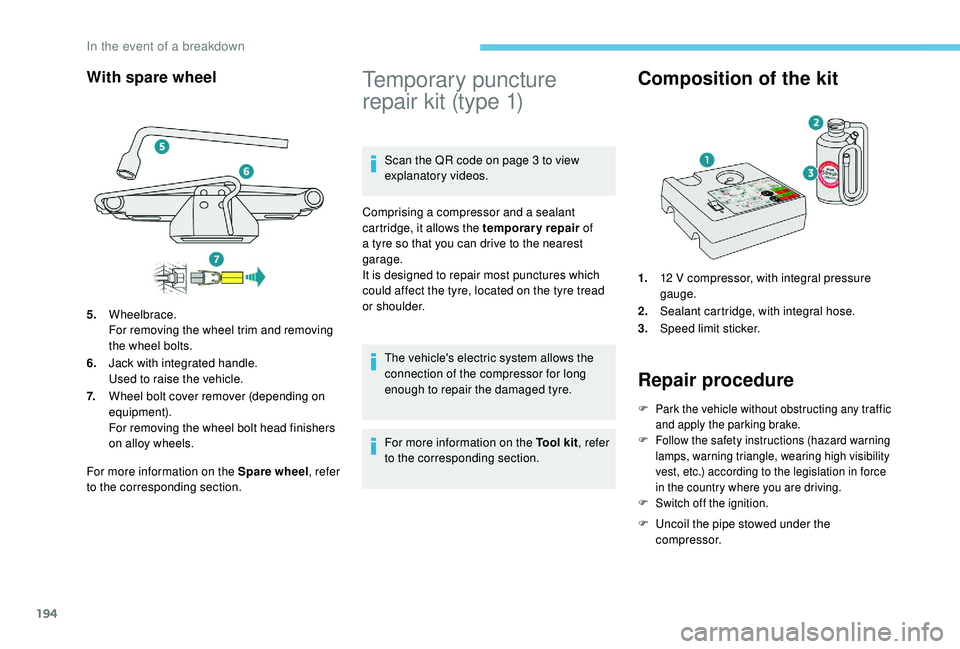
5.
Wheelbrace.
For removing the wheel trim and removing
the wheel bolts.
6. Jack with integrated handle.
Used to raise the vehicle.
7. Wheel bolt cover remover (depending on
equipment).
For removing the wheel bolt head finishers
on alloy wheels.
In the event of a breakdown
Page 200 of 324
198
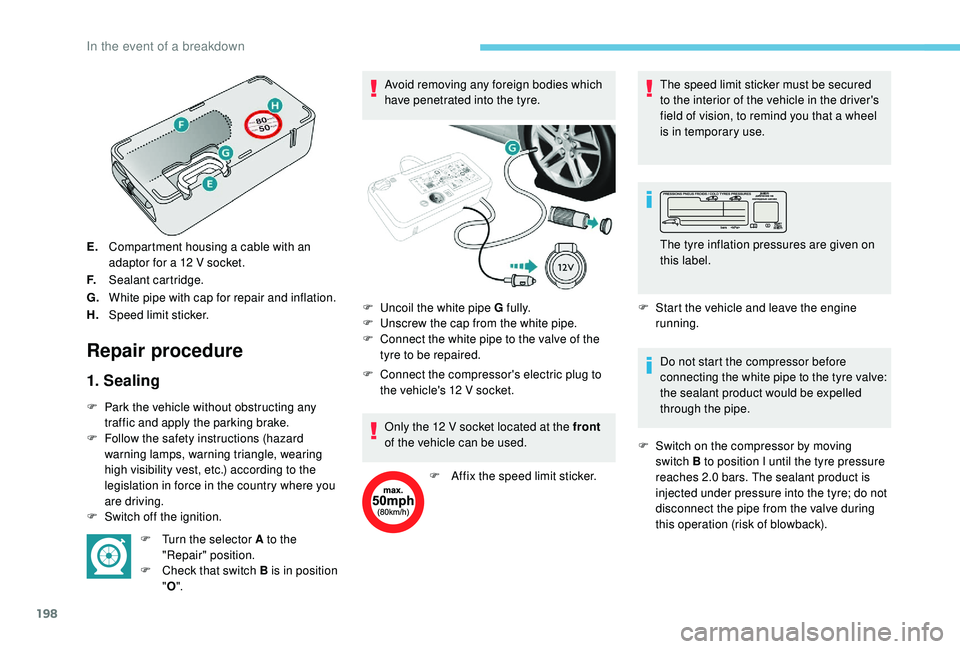
E.Compartment housing a cable with an
adaptor for a 12
V socket.
F. Sealant cartridge.
G. White pipe with cap for repair and inflation.
H. Speed limit sticker.
Repair procedure
1. Sealing
F Park the vehicle without obstructing any
traffic and apply the parking brake.
F
F
ollow the safety instructions (hazard
warning lamps, warning triangle, wearing
high visibility vest, etc.) according to the
legislation in force in the country where you
are driving.
F
S
witch off the ignition. F
T
urn the selector A to the
"Repair" position.
F
C
heck that switch B is in position
" O ". Avoid removing any foreign bodies which
have penetrated into the tyre.
F
C
onnect the compressor's electric plug to
the vehicle's 12 V socket.
Only the 12 V socket located at the front
of the vehicle can be used.
F
A
ffix the speed limit sticker.The speed limit sticker must be secured
to the interior of the vehicle in the driver's
field of vision, to remind you that a wheel
is in temporary use.
F
S
tart the vehicle and leave the engine
running.
Do not start the compressor before
connecting the white pipe to the tyre valve:
the sealant product would be expelled
through the pipe.
F
S
witch on the compressor by moving
switch B to position I until the tyre pressure
reaches 2.0
bars. The sealant product is
injected under pressure into the tyre; do not
disconnect the pipe from the valve during
this operation (risk of blowback).
F
U
ncoil the white pipe G fully.
F
U
nscrew the cap from the white pipe.
F
C
onnect the white pipe to the valve of the
tyre to be repaired. The tyre inflation pressures are given on
this label.
In the event of a breakdown
Page 203 of 324
201
F Adjust the pressure using the compressor (to inflate: switch B in position " I"; to deflate:
switch B in position " O" and press button
C ), according to the vehicle's tyre pressure
label.
If after approximately seven minutes this
pressure is not reached, this indicates
that the tyre is not repairable; contact a
PEUGEOT dealer or a qualified workshop
for assistance.
F
R
emove the kit then stow it.
Do not drive more than 125
miles (200 km)
with the repaired tyre; see a PEUGEOT
dealer or a qualified workshop to change
the tyre.
Should the pressure of one or more tyres
be adjusted, it is necessary to reinitialise
the under-inflation detection system.
For more information on Tyre under-
inflation detection , refer to the
corresponding section.Spare wheel
Scan the QR code on page 3 to view
explanatory videos.
Procedure for changing a damaged wheel with
the spare wheel using the tools provided with
the vehicle. For more information on the Tool kit , refer
to the corresponding section.
The jack must only be used to change
a wheel with a damaged or punctured tyre.
The jack does not require any
maintenance.
The jack meets European standards,
as defined in the Machinery Directive
2006/42/EC.
Wheel with wheel trim
When refitting the wheel , refit the wheel
trim, starting by placing its aperture in
line with the valve and then pushing it into
place all round its edge with the palm of
your hand. F
P
ark the vehicle without obstructing any
traffic and apply the parking brake.
F F ollow the safety instructions (hazard
warning lamps, warning triangle, wearing
high visibility vest, etc.) according to the
legislation in force in the country where you
are driving.
F
S
witch off the ignition.
Access to the spare wheel
The spare wheel is installed in the boot under
t h e f l o o r.
Depending on the country of sale, the spare
wheel may be steel, alloy or of the "space-
saver" type.
For access to the spare wheel, first refer to the
section on the Tool kit.
8
In the event of a breakdown
Page 204 of 324
202
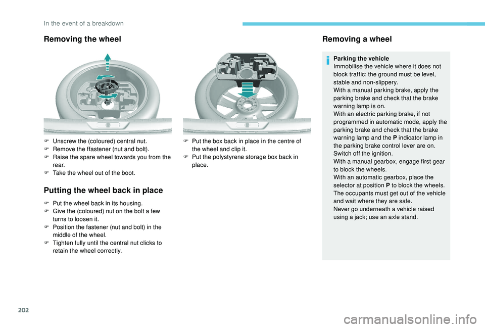
Removing the wheel
Putting the wheel back in place
F Put the wheel back in its housing.
F G ive the (coloured) nut on the bolt a few
turns to loosen it.
F
P
osition the fastener (nut and bolt) in the
middle of the wheel.
F
T
ighten fully until the central nut clicks to
retain the wheel correctly.
Removing a wheel
Parking the vehicle
Immobilise the vehicle where it does not
block traffic: the ground must be level,
stable and non-slippery.
With a manual parking brake, apply the
parking brake and check that the brake
warning lamp is on.
With an electric parking brake, if not
programmed in automatic mode, apply the
parking brake and check that the brake
warning lamp and the P indicator lamp in
the parking brake control lever are on.
Switch off the ignition.
With a manual gearbox, engage first gear
to block the wheels.
With an automatic gearbox, place the
selector at position P to block the wheels.
The occupants must get out of the vehicle
and wait where they are safe.
Never go underneath a vehicle raised
using a jack; use an axle stand.
F
U
nscrew the (coloured) central nut.
F
R
emove the ffastener (nut and bolt).
F
R
aise the spare wheel towards you from the
r e a r.
F
T
ake the wheel out of the boot. F
P
ut the box back in place in the centre of
the wheel and clip it.
F
P
ut the polystyrene storage box back in
place.
In the event of a breakdown
Page 211 of 324
209
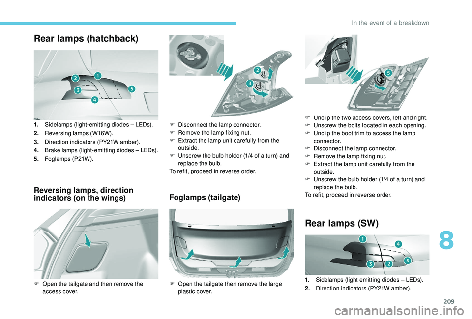
Rear lamps (hatchback)
1.Sidelamps (light-emitting diodes – LEDs).
2. Reversing lamps (W16W).
3. Direction indicators (PY21W amber).
4. Brake lamps (light-emitting diodes – LEDs).
5. Foglamps (P21W).
Reversing lamps, direction
indicators (on the wings) Foglamps (tailgate)
F Open the tailgate and then remove the
access cover. F
D
isconnect the lamp connector.
F
R
emove the lamp fixing nut.
F
E
xtract the lamp unit carefully from the
outside.
F
U
nscrew the bulb holder (1/4 of a turn) and
replace the bulb.
To refit, proceed in reverse order.
F O pen the tailgate then remove the large
plastic cover.
Rear lamps (SW)
F Unclip the two access covers, left and right.
F U nscrew the bolts located in each opening.
F
U
nclip the boot trim to access the lamp
connector.
F
D
isconnect the lamp connector.
F
R
emove the lamp fixing nut.
F
E
xtract the lamp unit carefully from the
outside.
F
U
nscrew the bulb holder (1/4 of a turn) and
replace the bulb.
To refit, proceed in reverse order.
1. Sidelamps (light emitting diodes – LEDs).
2. Direction indicators (PY21W amber).
8
In the event of a breakdown