brake PEUGEOT 4008 2015 Owner's Manual
[x] Cancel search | Manufacturer: PEUGEOT, Model Year: 2015, Model line: 4008, Model: PEUGEOT 4008 2015Pages: 389, PDF Size: 15.89 MB
Page 117 of 389
115
4008_en_Chap04_conduite_ed01-2014
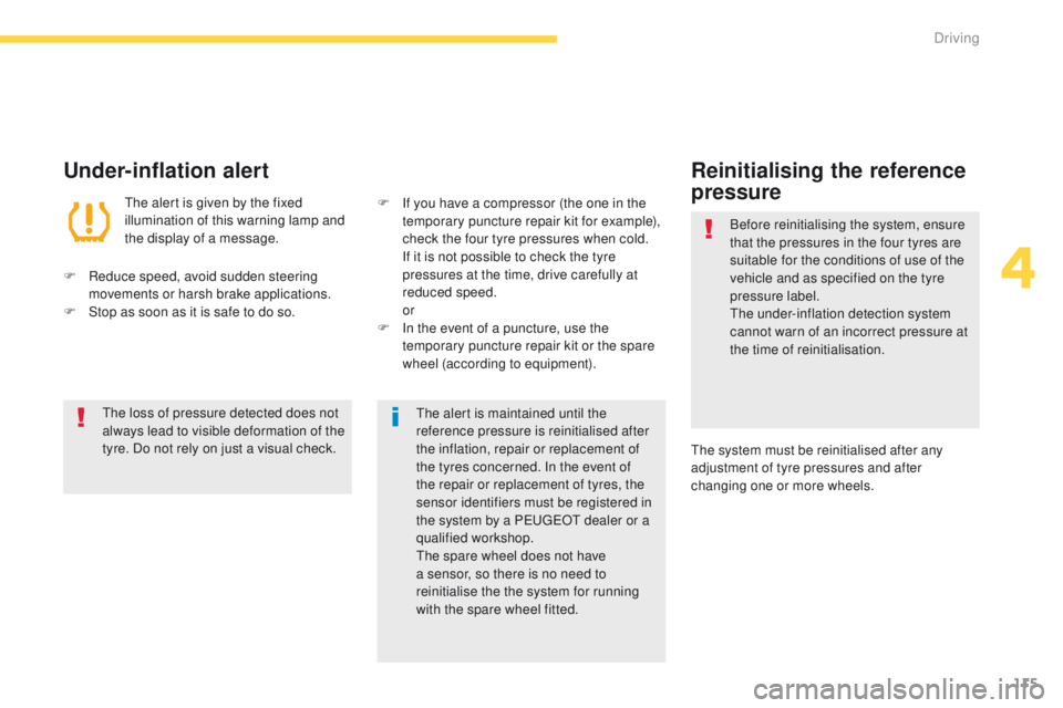
Under-inflation alert
the alert is given by the fixed
illumination of this warning lamp and
the display of a message.
F
R
educe speed, avoid sudden steering
movements or harsh brake applications.
F
S
top as soon as it is safe to do so.
th
e loss of pressure detected does not
always lead to visible deformation of the
tyre. Do not rely on just a visual check.
th
e alert is maintained until the
reference pressure is reinitialised after
the inflation, repair or replacement of
the tyres concerned. In the event of
the repair or replacement of tyres, the
sensor identifiers must be registered in
the system by a P
e
uge
Ot
dealer or a
qualified workshop.
th
e spare wheel does not have
a sensor, so there is no need to
reinitialise the the system for running
with the spare wheel fitted.
F
I f you have a compressor (the one in the
temporary puncture repair kit for example),
check the four tyre pressures when cold.
I
f it is not possible to check the tyre
pressures at the time, drive carefully at
reduced speed.
or
F
I
n the event of a puncture, use the
temporary puncture repair kit or the spare
wheel (according to equipment).
Reinitialising the reference
pressure
Before reinitialising the system, ensure
that the pressures in the four tyres are
suitable for the conditions of use of the
vehicle and as specified on the tyre
pressure label.
th
e under-inflation detection system
cannot warn of an incorrect pressure at
the time of reinitialisation.
th
e system must be reinitialised after any
adjustment of tyre pressures and after
changing one or more wheels.
4
Driving
Page 122 of 389
120
4008_en_Chap04_conduite_ed01-2014
Cruise control
System which automatically maintains the vehicle speed at the value programmed by the driver, without any action on the accelerator pedal.
th
e cruise control is switched on manually:
the vehicle speed must be at least 25 mph
(40 km/h) and second gear or higher must be
engaged in the case of a manual gearbox.
th
e cruise control is switched off manually, by
an action on the brake or clutch pedal or if the
ASC system is triggered.
th
e programmed speed can be exceeded
temporarily by pressing the accelerator pedal.
th
e cruise control cannot, in any
circumstances, take the place of the
need to comply with speed limits or of the
vigilance and responsibility of the driver.
th
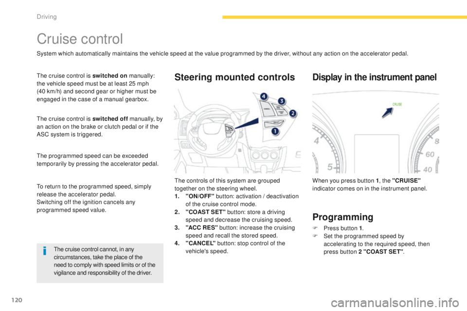
e controls of this system are grouped
together on the steering wheel.
1.
"
ON/OFF" button: activation / deactivation
of the cruise control mode.
2.
"
COAST SET" button: store a driving
speed and decrease the cruising speed.
3.
"A
CC R ES" button: increase the cruising
speed and recall the stored speed.
4.
"C
ANCEL" button: stop control of the
vehicle's speed.
Steering mounted controls
When you press button 1 , the "CRUISE"
indicator comes on in the instrument panel.
Display in the instrument panel
Programming
F Press button 1 .
F S et the programmed speed by
accelerating
to the required speed, then
press button 2 "COAST SET" .
to r
eturn to the programmed speed, simply
release the accelerator pedal.
Switching off the ignition cancels any
programmed speed value.
Driving
Page 123 of 389
121
4008_en_Chap04_conduite_ed01-2014
Increasing the programmed
speedDecreasing the
programmed speedTemporary acceleration/
deceleration
Temporary acceleration
Press the accelerator pedal as normal. When
the pedal is released, you return to the stored
speed.
F
u
sing button 2 "COAST SET"
:
-
s
uccessive presses decrease the speed in
steps of approximately 1 mph (1.6 km/h).
-
a m
aintained press of this button
decreases the speed progressively.
Once the speed required has been reached,
release the button, the new speed is stored.
F
u
s
ing the brake pedal:
-
b
rake to deactivate the cruise control, then
press button 2 "COAST SET" . Release to
store the new speed.
F
u
sing button 3 "ACC RES"
:
-
s
uccessive presses increase the speed in
steps of approximately 1 mph (1.6 km/h).
-
a m
aintained press of this button increases
the programmed speed progressively.
Once the speed required has been reached,
release the button, the new speed is stored.
F
u
s
ing the accelerator pedal:
-
a
ccelerate to reach the speed required,
then press button 2 "COAST SET" .
Release the button to store the new speed.
Temporary deceleration
Press the brake pedal to reduce the speed. to r eturn to the stored speed, press button 3
"ACC R ES" .
4
Driving
Page 124 of 389
122
4008_en_Chap04_conduite_ed01-2014
When the cruise control is in operation,
pay attention if you press and hold one
of the programmed speed adjustment
buttons: this can result in a very rapid
change in the speed of your vehicle.
Do not use the cruise control on
slippery roads or in heavy traffic.
On a steep descent, the cruise control
will not be able to prevent the vehicle
from exceeding the programmed speed.
to p
revent the mat from becoming
caught under the pedals:
-
e
nsure that the mat is positioned
c o r r e c t l y,
-
n
ever fit one mat on top of another.to
deactivate the cruise control:
F
p
ress the brake or clutch pedal, or
F
p
ress button 1 "ON OFF" , or
F
p
ress button 4 "CANCEL" .
Deactivating the function Reactivating the function
When the cruise control has been deactivated
using the button 4 "CANCEL" , you can return
to the stored speed by pressing button 3 "ACC
RES" when you reach a minimum speed of
25
mph (40 km/h).
th
e cruise control may be deactivated
automatically:
F
w
hen the vehicle reaches a speed below
20 mph (35 km/h),
F
w
hen the active stability control system
(ASC) comes into operation.
Driving
Page 144 of 389
142
4008_en_Chap06_securite_ed01-2014
group of supplementary systems which help
you to obtain optimum braking in complete
safety in emergency situations:
-
a
nti-lock braking system (ABS),
-
e
lectronic brake force distribution (
eB
FD).
Braking assistance systems
Anti-lock braking system
and electronic brake force
distribution
Linked systems which improve the stability and
manoeuvrability of your vehicle when braking,
in particular on poor or slippery sur faces.
Activation
the anti-lock braking system is active if the
vehicle speed is higher than 6 mph (10 km/h).
It is deactivated when the vehicle speed falls
below 3
mph (5 km/h).
th
e anti-lock braking system comes into
operation automatically when there is a risk of
wheel lock.
Normal operation of the ABS may make itself
felt by slight vibration of the brake pedal.
Operating fault
When the vehicle is stationary
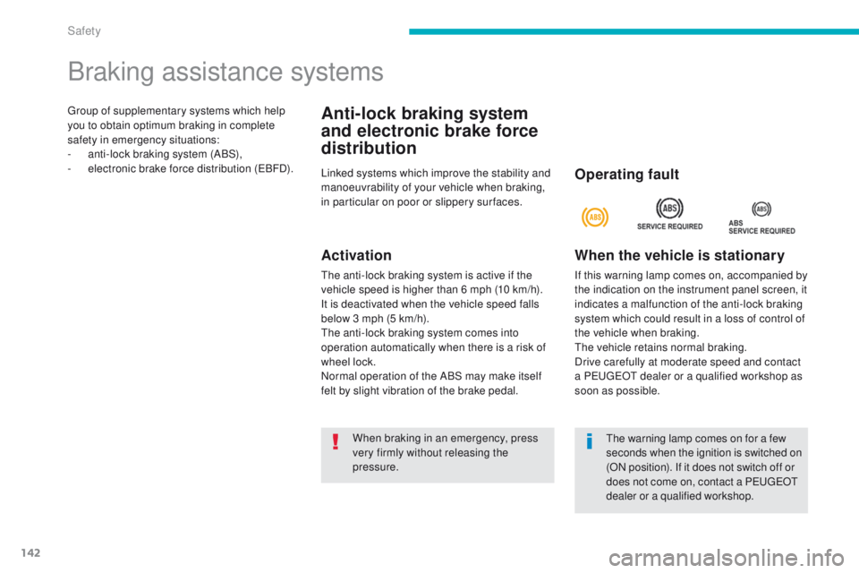
If this warning lamp comes on, accompanied by
the indication on the instrument panel screen, it
indicates a malfunction of the anti-lock braking
system which could result in a loss of control of
the vehicle when braking.
th
e vehicle retains normal braking.
Drive carefully at moderate speed and contact
a P
e
uge
Ot
dealer or a qualified workshop as
soon as possible.
When braking in an emergency, press
very firmly without releasing the
pressure.
th
e warning lamp comes on for a few
seconds when the ignition is switched on
(ON position). If it does not switch off or
does not come on, contact a P
e
uge
Ot
d
ealer or a qualified workshop.
Safety
Page 145 of 389
143
4008_en_Chap06_securite_ed01-2014
When the vehicle is moving
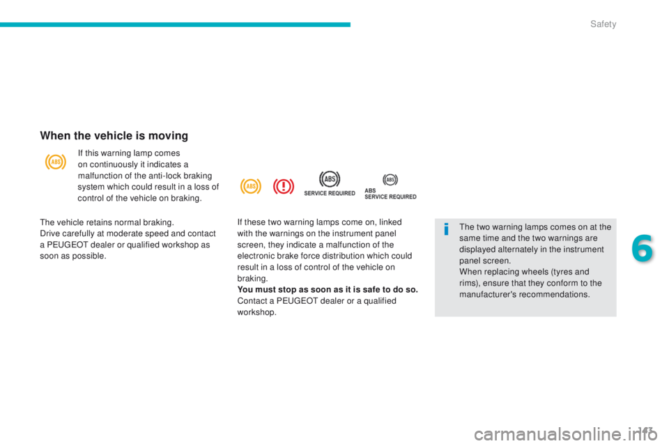
If this warning lamp comes
on continuously it indicates a
malfunction of the anti-lock braking
system which could result in a loss of
control of the vehicle on braking.
th
e two warning lamps comes on at the
same time and the two warnings are
displayed alternately in the instrument
panel screen.
When replacing wheels (tyres and
rims), ensure that they conform to the
manufacturer's recommendations.
th
e vehicle retains normal braking.
Drive carefully at moderate speed and contact
a P
e
uge
Ot
dealer or qualified workshop as
soon as possible. If these two warning lamps come on, linked
with the warnings on the instrument panel
screen, they indicate a malfunction of the
electronic brake force distribution which could
result in a loss of control of the vehicle on
braking.
You must stop as soon as it is safe to do so.
Contact a P
e
uge
Ot
dealer or a qualified
workshop.
6
Safety
Page 146 of 389

144
4008_en_Chap06_securite_ed01-2014
Associated systems which guarantee the directional stability of the vehicle within the limits of the laws of physics:
- t raction control (tC L),
-
a
ctive stability control (ASC).
Traction control and active stability control
traction control optimises traction to prevent
wheel spin, by acting on the brakes of the
driving wheels and on the engine.
Active stability control acts on the brake of one
or more wheels and on the engine to keep the
vehicle on the trajectory required by the driver.Activation
these systems are activated automatically
each time the vehicle is started.
th
e illumination of this warning lamp
in the instrument panel indicates
that the ASC and
t
C
L systems are
deactivated.
Deactivation
In exceptional conditions (starting a vehicle
which is bogged down, stuck in snow, on soft
ground, ...), it may be advisable to deactivate
the ASC system, so that the wheels can move
freely and regain grip.
th
is is indicated by flashing of this
symbol on the instrument panel
screen.
trajectory control systems
F Press this button, located to the left of the steering wheel, until the symbol appears in
the instrument panel screen.
Operation
they operate when the vehicle speed is higher
than 10 mph (15 km/h).
th
ey come into operation in the event of a grip
or trajectory problem.
Safety
Page 174 of 389
172
4008_en_Chap07_info-pratiques_ed01-2014
After repairing the tyre, the speed
restriction sticker should be affixed to
the centre of vehicle's steering wheel to
remind you that this wheel must only be
used temporarily.
Do not exceed a speed of 50 mph
(80 km/h) when driving with a tyre
repaired using this type of kit.
Repair procedure
F Stop the vehicle in as safe a location as possible and on a level and stable sur face.
e
n
sure that the tyre valve is not at the
bottom of the wheel, in contact with the
ground.
F
A
pply the parking brake.
F
P
lace the gear lever in position R for
vehicle with a manual gearbox, or in
position P for vehicles fitted with a CV
t
gearbox.
F
S
witch off the ignition.
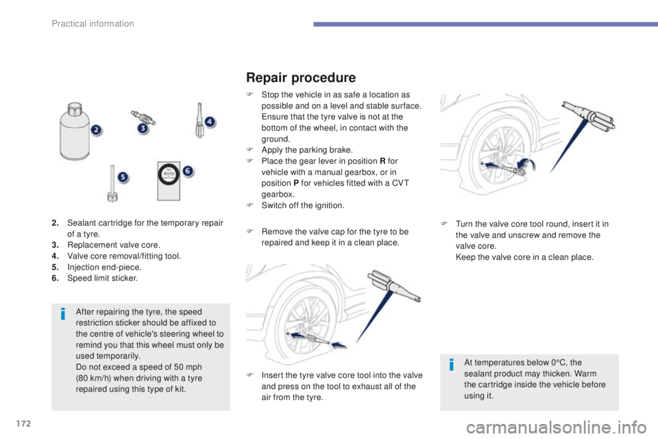
2.
S
ealant cartridge for the temporary repair
of a tyre.
3.
R
eplacement valve core.
4.
V
alve core removal/fitting tool.
5.
I
njection end-piece.
6.
Spe
ed limit sticker. F
R
emove the valve cap for the tyre to be
repaired and keep it in a clean place.
At temperatures below 0°C, the
sealant product may thicken. Warm
the cartridge inside the vehicle before
using it.
F
t
u
rn the valve core tool round, insert it in
the valve and unscrew and remove the
valve core.
K
eep the valve core in a clean place.
F
I
nsert the tyre valve core tool into the valve
and press on the tool to exhaust all of the
air from the tyre.
Practical information
Page 179 of 389
177
4008_en_Chap07_info-pratiques_ed01-2014
Removing a wheel
Parking the vehicle
Immobilise the vehicle where it does not
block traffic: if possible, park the vehicle
on level, stable and non-slippery
ground.
Apply the parking brake, switch off the
ignition and engage first gear to lock
the wheels.
If necessary, place a chock under the
wheel diagonally opposite the wheel to
be changed.
Never go underneath a vehicle raised
using a jack; use a stand.
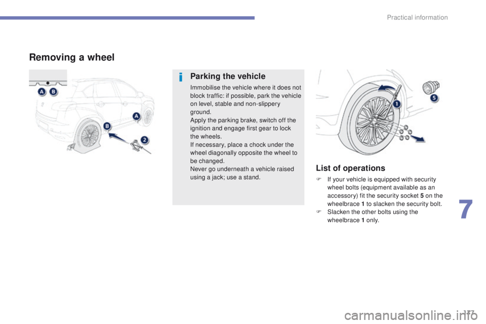
List of operations
F If your vehicle is equipped with security wheel bolts (equipment available as an
accessory) fit the security socket 5 on the
wheelbrace 1 to slacken the security bolt.
F
S
lacken the other bolts using the
wheelbrace 1 o n l y.
7
Practical information
Page 183 of 389
181
4008_en_Chap07_info-pratiques_ed01-2014
For more information on snow chains,
contact a PeugeOt dealer or a
qualified workshop.
Snow chains
In wintry conditions, snow chains improve traction as well as the behaviour of the vehicle when
braking.
Advice on installation
F If you have to fit the chains during a journey, stop the vehicle on a flat sur face
on the side of the road.
F
A
pply the parking brake and position any
wheel chocks to prevent movement of
your vehicle.
F
F
it the chains following the instructions
provided by the manufacturer.
F
M
ove off gently and drive for a few
moments, without exceeding 30 mph
(50 km/h).
F
S
top your vehicle and check that the snow
chains are correctly tightened.
th
e snow chains must be fitted only
to the front wheels.
th
ey must never
be fitted to "space-saver" type spare
wheels.
ta
ke account of the legislation in force
in your country on the use of snow
chains and the maximum running speed
authorised.
Avoid driving with snow chains on roads
that have been cleared of snow, to
avoid damaging your vehicle's tyres and
the road sur face. If your vehicle is fitted
with alloy wheels, check that no part of
the chain or its fixings is in contact with
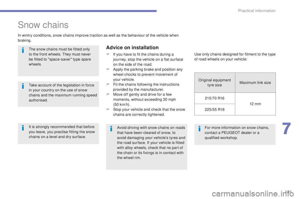
the wheel rim.us e only chains designed for fitment to the type
of road wheels on your vehicle:
Original equipment tyre size Maximum link size
215/ 70 R16 12 mm
225/55 R18
It is strongly recommended that before
you leave, you practise fitting the snow
chains on a level and dry sur face.
7
Practical information