air conditioning PEUGEOT BOXER 2015 User Guide
[x] Cancel search | Manufacturer: PEUGEOT, Model Year: 2015, Model line: BOXER, Model: PEUGEOT BOXER 2015Pages: 276, PDF Size: 8.99 MB
Page 63 of 276
61
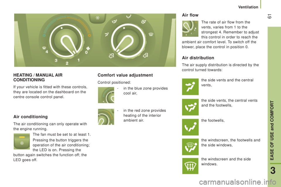
HEAtInG / MAnuAL AIr
condItIonInG
If your vehicle is fitted with these controls,
they are located on the dashboard on the
centre console control panel.
comfort value adjustment Air flow
the rate of air flow from the
vents, varies from 1 to the
strongest 4. Remember to adjust
this control in order to reach the
ambient air comfort level.
to switch off the
blower, place the control in position 0.
Air conditioning
the air conditioning can only operate with
the engine running.
the fan must be set to at least 1.
Pressing the button triggers the
operation of the air conditioning;
the L
eD is on. Pressing the
button again switches the function off; the
L
eD goes of
f.
Air distribution
the air supply distribution is directed by the
control turned towards:
the side vents and the central
vents,
the side vents, the central vents
and the footwells,
the footwells,
the windscreen, the footwells and
the side windows,
the windscreen and the side
windows.
-
in the blue zone provides
cool
air
,
-
in the red zone provides
heating of the interior
ambient
air
.
Control positioned:
3
EASE oF uSE and coMFort
Ventilation
Page 64 of 276

62Intake of exterior airrecommended settings for the manual air conditioning
For optimum operation of this system, the settings below are recommended\
:
recirculation of interior air
this position should only be
temporary.
used with the air conditioning
switched on and the fan setting
(from 1 to 4), recirculation enables you to
obtain the required ambient air comfort level
with both hot or cold settings.
Recirculation temporarily prevents exterior
odours and smoke from entering the
passenger compartment. If I require...
Air
distributiontemperature Air flow Air
recirculation AC
Heating -
Cooling
Demisting
Defrosting
When your ambient air comfort level has
been reached, return to the intake of exterior
air position to permit renewal of the air in the
passenger compartment and demisting.
this
is the preferred operating mode.
this is the preferred operating
position.
Ventilation
Page 65 of 276
63
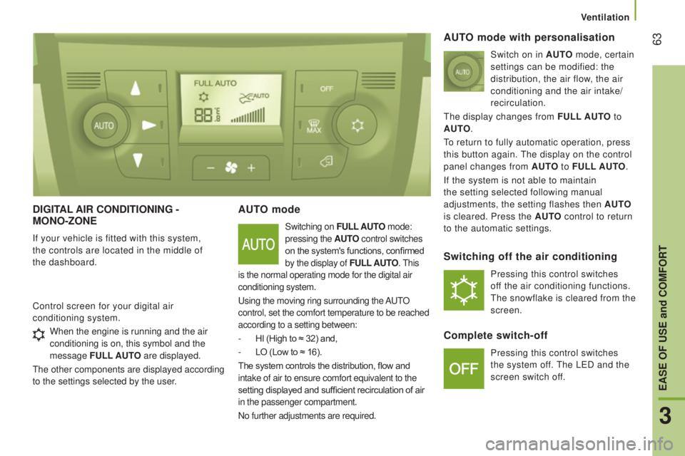
dIGItAL AIr condItIonInG -
Mono-zonE
If your vehicle is fitted with this system,
the controls are located in the middle of
the
dashboard.
Auto mode
Switching on FuLL Auto mode:
pressing the A
ut
o
control switches
on the system's functions, confirmed
by the display of F
uLL
A
ut
o
. this
is the normal operating mode for the digital air
conditioning system.
using the moving ring surrounding the
A
utO
control, set the comfort temperature to be reached
according to a setting between:
-
HI (High to ≈ 32) and,
-
LO (Low to ≈ 16).
The system controls the distribution, flow and
intake of air to ensure comfort equivalent to the
setting displayed and sufficient recirculation of air
in the passenger compartment.
No further adjustments are required.
Control screen for your digital air
conditioning system.
Auto mode with personalisation
Switch on in Auto mode, certain
settings can be modified: the
distribution, the air flow
, the air
conditioning and the air intake/
recirculation.
the display changes from
F
uLL
A
ut
o
t
o
A
ut
o
.
to return to fully automatic operation, press
this button again.
the display on the control
panel changes from A
ut
o
to
F
uLL
A
ut
o
.
If the system is not able to maintain
the setting selected following manual
adjustments, the setting flashes then A
ut
o
is cleared. Press the A
ut
o
control to return
to the automatic settings.
Switching off the air conditioning
Pressing this control switches
off the air conditioning functions.
the snowflake is cleared from the
screen.
complete switch-off
Pressing this control switches
the system off.
the LeD and the
screen switch off.
When the engine is running and the air
conditioning is on, this symbol and the
message FuLL
Aut
o are displayed.
the other components are displayed according
to the settings selected by the user
.
3
EASE oF uSE and coMFort
Ventilation
Page 66 of 276

64comfort value adjustment ring
the settings range between:
-
increasing the interior ambient air
temperature HI (High) which goes up to
to a maximum setting of 32,
-
cooling the interior ambient air
temperature LO (Low) which goes down
to a setting of 16.
Air distribution
A press illuminates the LeD on the buttons
which distribute the air flow towards:
the windscreen and front side
window vents (demisting/
defrosting the windows),
the central and side vents (chest
and face),
the vents in the front and rear
areas (feet).
the combination of buttons permits
improvement of air distribution.
Air flow
Successive presses of this button
increase (+) or reduce (-) the
force of the air flow to the interior.
Intake of exterior air / recirculation of interior air
When the LeD is on, the air
recirculates inside the passenger
compartment to prevent the entry of exterior
odours and smoke.
this position should be
temporary.
When the ambient air comfort level has been
reached, pressing the button switches the
L
eD of
f and reopens the exterior air intake.
Pressing the A
ut
o
button also restores
the intake of exterior air. Returning to this
position permits renewal of the air in the
passenger compartment and demisting.
Pressing the A
ut
o
button again restores
the F
uLL
A
ut
o
function.
rapid demisting / defrosting
Pressing this control permits
rapid clearing of the windows.
the LeD is on.
the system manages the air conditioning,
the flow and intake of air, the defrosting
of the rear screen and provides optimum
distribution of the air to the windscreen and
front side windows.
If your vehicle is fitted with additional
heating, switch it off to ensure rapid and
effective demisting/defrosting.
AddItIonAL rEAr VEntILAtIon
the controls for this system, additional to
the standard cabin ventilation system, are
on the lower dashboard, to the left of the
steering wheel.
Air outlet
A press on this control activates
the extraction of air to the
outside; the L
eD comes on.
Press again to switch off.
Air inlet
A press on this control activates
the entry of air into the cabin; the
L
eD comes on. Press again to
switch off.
Ventilation
Page 67 of 276
65AddItIonAL HEAtInG SYStEMS
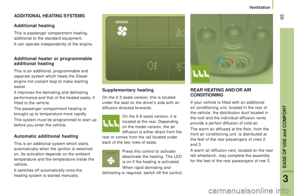
Supplementary heating
On the 2-3 seats version, this is located
under the seat on the driver's side with air
diffusion directed forwards.
rEAr HEAtInG And/or AIr
condItIonInG
If your vehicle is fitted with an additional
air conditioning unit, located in the rear of
the vehicle: the distribution duct located in
the roof and the individual diffusion vents
provide a perfect diffusion of cold air.
the warm air dif
fused at the floor, from the
front air conditioning unit, is distributed at
the feet of the rear passengers of rows 2
and 3.
A warm air diffusion vent, located on the rear
left wheelarch, may complete the assembly
for the feet of the rear passengers of row 3.
Additional heating
this is passenger compartment heating,
additional to the standard equipment.
It can operate independently of the engine.
Additional heater or programmable
additional heating
this is an additional, programmable and
separate system which heats the Diesel
engine hot coolant loop to make starting
easier.
It improves the demisting and defrosting
performance and that of the heated seats, if
fitted to the vehicle.
the passenger compartment heating is
brought up to temperature more rapidly.
this system must be programmed to start up
before you enter the vehicle. On the 5-9 seats version, it is
located at the rear. Depending
on the model version, the air
diffusion is either direct from the
rear or comes from the rail located under
each of the two rows of seats.
Press this control to activate/
deactivate the heating.
the LeD
is on if the heating is activated.
When rapid demisting and
defrosting is required, switch off the control.
Automatic additional heating
this is an additional system which starts
automatically when the ignition is switched
on. Its activation depends on the ambient
temperature and the temperature inside the
vehicle.
It switches off automatically once the
heating system is started manually.
3
EASE oF uSE and coMFort
Ventilation
Page 125 of 276
123
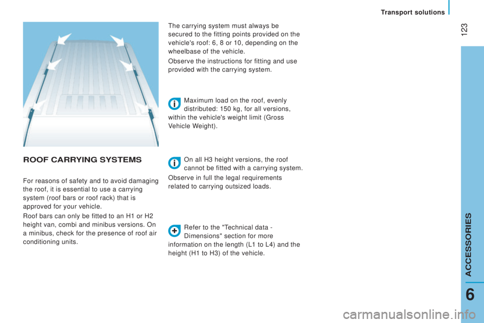
rooF cArrYInG SYStEMS
Refer to the "technical data -
Dimensions" section for more
information on the length (L1 to L4) and the
height (H1 to H3) of the vehicle. Maximum load on the roof, evenly
distributed: 150 kg, for all versions,
within the vehicle's weight limit (
gross
Vehicle Weight).
For reasons of safety and to avoid damaging
the roof, it is essential to use a carrying
system (roof bars or roof rack) that is
approved for your vehicle.
Roof bars can only be fitted to an H1 or H2
height van, combi and minibus versions. On
a minibus, check for the presence of roof air
conditioning units.
the carrying system must always be
secured to the fitting points provided on the
vehicle's roof: 6, 8 or 10, depending on the
wheelbase of the vehicle.
Observe the instructions for fitting and use
provided with the carrying system.
On all H3 height versions, the roof
cannot be fitted with a carrying system.
Observe in full the legal requirements
related to carrying outsized loads.
6
transport solutions
ACCeSSORIeS
Page 133 of 276

131
the presence of this label, in particular with
the Stop & Start system, indicates the use of
a specific 12
V lead-acid battery with special
technology and specification.
The involvement
of a PEUGEOT dealer or a qualified workshop
is essential when replacing or disconnecting
the battery.
these operations will keep your vehicle
in good running order. Ask for advice
from a P
eugeOt dealer or refer to the
warranty and maintenance record included
in the handbook pack.
cHEcKS
Battery
At the start of winter, have your battery
checked by a P
eugeOt dealer or a
qualified workshop.
Bleeding water from the diesel
filter
If this warning lamp comes on,
bleed the filter, or bleed regularly
each time the engine oil is
changed.
to drain the water out, unscrew the bleed
screw or the water in Diesel sensor
, located
at the base of the filter. Leave open until
all of the water has been drained out.
then
tighten the bleed screw or the water sensor.
Air filter and passenger
compartment filter
A clogged passenger compartment filter
may reduce the performance of the
air conditioning system and generate
undesirable odours.
the replacement
intervals for these components are given in
the warranty and maintenance record.
Depending on the environment (dusty
atmosphere...) and the use of the vehicle
(urban driving...), change them twice as
often if necessary.
Refer to the "Checks -
under the
bonnet" section.
HDi engines use advanced technology.
All work requires a special qualification
which is guaranteed by a P
eugeOt dealer
or a qualified workshop.
7
CHeCKS
Levels and checks
Page 148 of 276
 Allocation
12 7.5Right-hand dipped headlamp
13 7.5Left-hand dipped headlamp
31 5
engine compartment control unit relay - Dashboard control unit relay (ig\
nition switch +)
32 7.5Cabi")
146FusesA (amps) Allocation
12 7.5Right-hand dipped headlamp
13 7.5Left-hand dipped headlamp
31 5
engine compartment control unit relay - Dashboard control unit relay (ig\
nition switch +)
32 7.5Cabin lighting (battery +)
33 7.5Battery check sensor on Stop & Start version (battery +)
34 7.5Minibus interior lighting - Hazard warning lamps
36 10Audio system -
Air conditioning controls - Alarm -
tachograph - Battery cut-off control unit -
Additional heating programmer (battery +)
37 7.5Brake lamp switch -
third brake lamp Instrument panel (ignition +)
38 20Central door locking (battery +)
42 5ABS control unit and sensor -
ASR sensor - DSC sensor - Brake lamp switch
43 20Windscreen wiper motor (ignition switch +)
47 20Driver's electric window motor
48 20Passenger's electric window motor
49 5Parking sensors control unit - Audio system - Steering mounted controls - Centre and side switch panels\
-
Auxiliary switch panel - Battery cut-off control unit (ignition switch +)
50 7.5Airbags and pre-tensioners control unit
51 5
tachograph - Power steering control unit - Air conditioning - Reversing lamps - W
ater in Diesel sensor -
Air flow sensor (ignition switch +)
53 7.5Instrument panel (battery +)
89 -Not used
90 7.5Left-hand main beam
91 7.5Right-hand main beam
92 7.5Left-hand front foglamp
93 7.5Right-hand front foglamp
Failed fuse
Page 150 of 276

148
Fuses in the engine compartment
Remove the nuts and tilt the box to access
the fuses.
refit the cover carefully after checking or
replacing fuses. Fuses
A (amps) Allocation
1 40ABS pump supply
2 50Diesel pre-heat unit
3 30Ignition switch - Starter motor
4 40Fuel heater
5 20/50Cabin ventilation with additional programmable heating
(battery +)
6 40/60Cabin fan maximum speed (battery +)
7 40/50/60 Cabin fan minimum speed (battery +)
8 40Cabin fan assembly (ignition switch +)
9 15Rear 12 V socket (battery +)
10 15Horn
11 -Not used
14 15Front 12 V socket (battery +)
15 15Cigarette lighter (battery +)
16 -Not used
17 -Not used
18 7.5
engine management control unit (battery +)
19 7.5Air conditioning compressor
20 30Screenwash/headlamp wash pump
21 15Fuel pump supply
22 -Not used
23 30ABS electrovalves
24 7.5Auxiliary switch panel - Door mirror controls and folding
(ignition switch +)
30 15Door mirror heating
Failed fuse