warning light PONTIAC BONNEVILLE 2003 Owners Manual
[x] Cancel search | Manufacturer: PONTIAC, Model Year: 2003, Model line: BONNEVILLE, Model: PONTIAC BONNEVILLE 2003Pages: 418, PDF Size: 20.24 MB
Page 2 of 418
The 2003 Pontiac Bonneville Owner Manual
Seats and Restraint Systems ........................... 1-1
Front Seats
............................................... 1-2
Safety Belts
.............................................. 1-7
Child Restraints
....................................... 1-27
Air Bag Systems
...................................... 1-47
Restraint System Check
............................ 1-56
Features and Controls ..................................... 2-1
Keys
........................................................ 2-3
Doors and Locks
...................................... 2-10
Windows
................................................. 2-1 9
Theft-Deterrent Systems
............................ 2-21
Starting and Operating Your Vehicle
........... 2-25
Mirrors
.................................................... 2-38
OnStap
.................................................. 2-40
HomeLink@ Transmitter
............................. 2-42
Storage Areas
......................................... 2-46
SlJnroof
................................................. 2-47
Vehicle Personalization
............................. 2-48
Instrument Panel ............................................. 3-1
Instrument Panel Overview
.......................... 3-4
Climate Controls
...................................... 3-25
Warning Lights, Gages and Indicators
......... 3-34
Systems Monitor
...................................... 3-55
Driver Information Center (DIC)
.................. 3-57 Secondary
Information Center (SIC)
............ 3-68
Audio System(s)
....................................... 3-71
Driving Your Vehicle ....................................... 4-1
Your Driving, the Road, and Your Vehicle
..... 4-2
Towing
................................................... 4-32
Service
..................................................... 5-3
Fuel
......................................................... 5-5
Checking Things Under the Hood
............... 5-12
Headlamp Aiming
..................................... 5-52
Bulb Replacement
.................................... 5-56
Windshield Wiper Blade Replacement
......... 5-61
Tires
...................................................... 5-62
Appearance Care
..................................... 5-82
Vehicle Identification
................................. 5-90
Electrical System
...................................... 5-91
C8pa.citigs
and Specifications ......... 5-100
Normal Maintenance Replacement Parts .... 5-101
Maintenance Schedule
................................ 6-2
Customer Assistance Information .................... 7-1
Customer Assistance Information
.................. 7-2
Reporting Safety Defects
............................ 7-8
index ................................................................ 1
Service and Appearance Care .......................... 5-1
Maintenance Schedule ..................................... 6-1
Page 5 of 418
Vehicle Damage Warnings
Also, in this book you will find these notices:
Notice: These mean there is something that could
damage your vehicle.
A notice will tell you about something that can damage
your vehicle. Many times, this damage would not be
covered by your warranty, and it could be costly. But the
notice will tell you what to do to help avoid the
damage.
When you read other manuals, you might see CAUTION
and NOTICE warnings in different colors or in different
words.
You’ll also see warning labels on your vehicle. They use
the same words, CAUTION or NOTICE.
Vehicle Symbols
Your vehicle may be equipped with components and
labels that use symbols instead of text. Symbols, used
on your vehicle, are shown along with the text
describing the operation or information relating to a
specific component, control, message, gage
or indicator
If you need help figuring out a specific name of a
component, gage or indicator reference the following
topics in the Index:
“Engine Compartment Overview’’
“Instrument Panel Overview”
“Climate Controls”
“Audio Systems”
Also see
Warning Lights, Gages and Indicators on
page 3-34.
iv
Page 91 of 418
OFF: This is the only position from which you can
remove the key. This position locks your ignition and
transaxle. It’s a theft-deterrent feature.
ACC (Accessory): In this position you can operate
your electrical accessories such as power windows,
sunroof (option), audio system and windshield wipers.
ON: This is the position the switch returns to after
you start your engine and release the switch. Even when
the engine is not running, you can use ON
to operate
your electrical accessories and to display some
instrument panel cluster warning lights. This is the
position for driving your vehicle.
START: This position starts the engine. When the
engine starts, release the key. The ignition switch will
return to
ON for normal driving.
Even
if the engine is not running, ACC and ON are
positions that allow you to operate your electrical
accessories.
Key Reminder Warning
If you leave your key in OFF you will hear a warning
tone when you open the driver’s door.
Retained Accessory Power (RAP)
After you turn the ignition off and remove the key, you
will still have power to such accessories as the
radio, sunroof (option) and power windows for up to
10 minutes. Power is turned off if you open a door.
Always leave your key in
OFF. If you leave your key in
any position other than
OFF, your battery will
discharge prematurely.
Starting Your Engine
Move your shift lever to PARK (P) or NEUTRAL (N).
Your engine won’t start in any other position - that’s a
safety feature. To restart when you’re already moving,
use NEUTRAL
(N) only.
Notice: Don’t try to shift to PARK (P) if your
vehicle
is moving. If you do, you could damage the
transaxle. Shift
to PARK (P) only when your
vehicle
is stopped.
1. With your foot off the accelerator pedal, turn your
ignition key to START. When the engine starts, let
go of the key. The idle speed will go down as
your engine gets warm.
2-26
Page 96 of 418
SECOND (2): This position gives you more power but
lower fuel economy.
You can use SECOND (2) on
hills. It can help control your speed as you go down
steep mountain roads, but then you would also want to
use your brakes
off and on.
Notice: Don’t drive in SECOND (2) for more than
5 miles (8 km), or at speeds over 55 mph (98 km/h),
or you can damage your transaxle. Use AUTOMATIC
OVERDRIVE
(@) or THIRD (3) as much as
possible.
Don’t shift into SECOND
(2) unless you are going
slower than
65 mph (105 km/h), or you can damage
your engine.
FIRST
(1): This position gives you even more power
but lower fuel economy than SECOND
(2). You can use
it on very steep hills, or
in deep snow or mud. If the
shift lever is put in
FIRST (l), the transaxle won’t shift
into first gear until the vehicle is going slowly enough.
Notice: If your front wheels won’t turn, don’t
try to drive. This might happen if you were stuck
in
very deep sand or mud or were up against a solid
object. You could damage your transaxle.
Also,
if you stop when going uphill, don’t hold your
vehicle there with only the accelerator pedal. This
could overheat and damage the transaxle. Use your
brakes to
hold your vehicle in position on a hill.
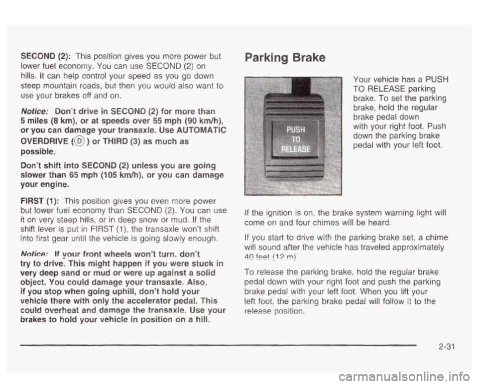
Parking Brake
Your vehicle has a PUSH
TO RELEASE parking
brake. To set the parking
brake, hold the regular
brake pedal down
with your right foot. Push
down the parking brake
pedal with your left foot.
If the ignition is on, the brake system warning light will
come on and four chimes will be heard.
If you start to drive with the parking brake set, a chime
will sound after the vehicle has traveled approximately
40 feet (1 2 m)
To release the parking brake, hold the regular brake
pedal down with your right foot and push the parking
brake pedal with your left foot. When you lift your
left foot, the parking brake pedal will follow it to the
release position.
2-3 1
Page 116 of 418
Section 3 Instrument Panel
Instrument Panel Overview ............................... 3.4
Hazard Warning Flashers
................................ 3.5
Other Warning Devises
................................... 3.6
Horn
............................................................. 3.6
Tilt Wheel
..................................................... 3.6
Turn SignaVMultifunction Lever
......................... 3.7
Exterior Lamps
............................................. 3.13
Interior Lamps
.............................................. 3.16
Head-Up Display (HUD)
................................. 3-21
Accessory Power Outlets
............................... 3.23
Ashtrays and Cigarette Lighter
........................ 3.24
Ciimate Controls ............................................ 3.25
Climate Control System ................................. 3.25
Automatic Climate Control System
................... 3.28
Outlet Adjustment
......................................... 3.32
Climate Controls Personalization
..................... 3.33
Warning Lights, Gages and Indicators ............. 3.34
Instrument Panel Cluster
................................ 3-35
Speedometer and Odometer
-8-38
Tachometer ................................................. 3.39
Safety Belt Reminder Light
............................. 3.39
. -- ..........................
Air Bag Readiness Light ............................. 3.40
Battery Warning bight
.................................... 3-41
Voltmeter Gage
............................................ 3-41
Brake System Warning Light
.......................... 3-42
Warning Light
........................................... 3-43
Traction Control System (TCS) Warning Light
...... 3-43
Low Traction Active Light ............................... 3-44
Engine Coolant Temperature Gage
.................. 3-45
Tire Pressure Light
....................................... 3-46
Anti-Lock
Brake System
Malfunction Indicator Lamp
....... ............... 3-46
Oil Pressure Gage
.................. ............... 3-49
Check Oil Level Light
J-50
Low Washer Fluid Warning Light ..................... 3-51
n ....................................
Security Light ............................................... 3-51
Check Gages Warning Light
........................... 3-51
Door Ajar Light
............................................. 3-52
Trunk Ajar Light
............................................ 3-52
............... 3-53
Fuel Gage
............................. ............... 3-53
Boost Gage
....................... ................... 3-54
Cnnrirn vu, Y . "1 \!nhirlo I . ..-.- Snnn - - - . lizht . ~
3- 1
Page 120 of 418
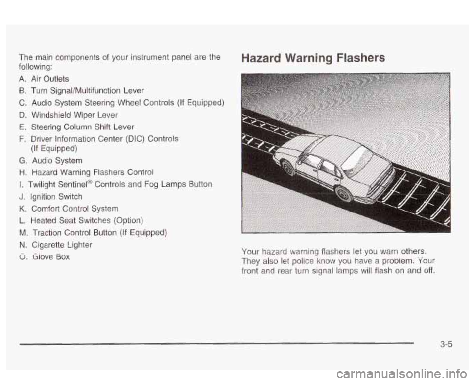
The main components of your instrument panel are the
following:
A. Air Outlets
B. Turn Signal/Multifunction Lever
C. Audio System Steering Wheel Controls (If Equipped)
D. Windshield Wiper Lever
E. Steering Column Shift Lever
F. Driver Information Center (DIC) Controls
G. Audio System
H. Hazard Warning Flashers Control
I. Twilight Sentinel@ Controls and Fog Lamps Button
J. Ignition Switch
K. Comfort Control System
L. Heated Seat Switches (Option)
M. Traction Control Button (If Equipped)
N. Cigarette Lighter
u. Giove Eox
(If Equipped)
Hazard Warning Flashers
Your hazard warning flashers let you warn others.
They also let police know you have a probiem. 'Your
front and rear turn signal lamps will flash on and
off.
3-5
Page 123 of 418
Turn Signal On Chime
If your turn signal is left on for more than 3/4 of a mile
(1.2 km), a chime will sound at each flash of the
turn signal. To turn
off the chime, move the turn signal
lever
to the off position.
Headlamp High/Low-Beam Changer
To change the headlamps from low beam to high beam,
push the lever forward. To change from high beam
to
low beam, pull the turn signal lever toward you,
then release it.
When the high beams are
on, this light on the
instrument panel cluster
will also be on.
Headlamps On Reminder
If you open the driver’s door while leaving the
headlamps or parking lamps
on and the key is in OFF,
you will hear a warning chime.
Flash-To-Pass
This feature lets you use your high-beam headlamps to
signal a driver in front of you that you want to pass.
It works even
if your headlamps are off.
To use it, pull the turn signal lever toward you.
If your headlamps are off or on low beam, your
high-beam headlamps will turn on. They’ll stay on as
long as you hold the lever toward you and the
high-beam indicator on the instrument panel cluster will
come on. Release the lever
to turn the high-beam
headlamps
off.
3-8
Page 125 of 418
Windshield Washer
At the end of the wiper lever, there’s a button. To spray
washer fluid on the windshield, push the button until
you have enough fluid to clean the windshield. The
wipers will clear the window and either stop or return to
yot set
speed.
~ -
In freezing weather, don’t use your washer
until the windshield is warmed. Otherwise the
washer fluid can form ice on the windshield,
blocking your vision.
Cruise Control
With cruise control, you can maintain a speed of about
25 mph (40 km/h) or more without keeping your foot
on the accelerator. This can really help
on long trips.
A WASHER FLUID warning light will indicate if the fluid
level in the windshield washer reservoir is low. See
Low Washer Fluid Warning Light on page 3-51.
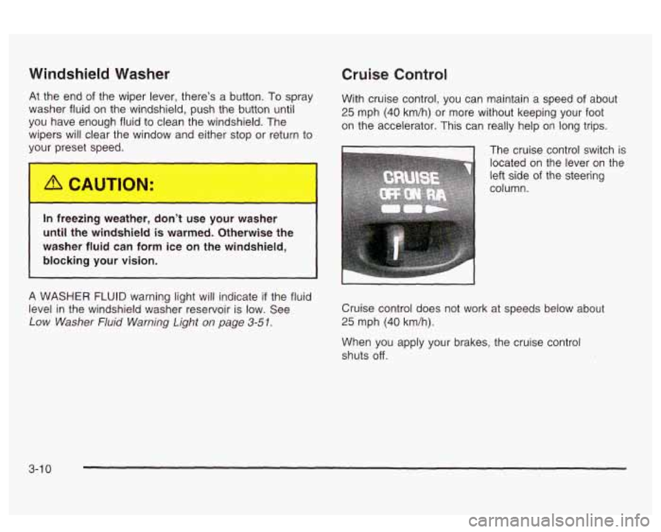
The cruise control switch is
located on the lever
on the
left side
of the steering
column.
Cruise control does not work at speeds below about
25 mph (40 km/h).
When you apply your brakes, the cruise control
shuts
off.
3-1 0
Page 136 of 418
Head-Up Display (HUD)
If the HUD image is too bright, or too high in
your field
of view, it may take you more time to
see things you need to see when it's dark
outside. Be sure to keep the HUD image dim
and placed low in your field of view.
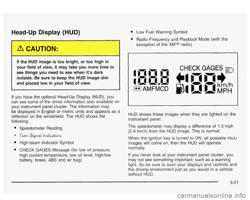
If you have the optional Head-Up Display (HUD), you
can see
some of the driver information also available 08
your instrument panel cluster. The information may
be displayed in English
or metric units and appears as a
reflection on the windshield. The HUD shows the
following:
Speedometer Reading
-- - I urrl Siyrlai i1-diCaki-S
High-beam Indicator Symbol
CHECK GAGES Message (for low oil pressure,
high coolant temperature, low oil level, high/low
battery, brake,
ABS and air bag)
Low Fuel Warning Symbol
Radio Frequency and Playback Mode (with the
exception of the
XMTM radio)
HUD shows these images when they are lighted on the
instrument panel.
The speedometer may display a difference of
1.5 mph
(2.4 km/h) from the HUD image. This is normal.
When the ignition key is turned to
ON, all possible HUU
images will come on, then the HUD will operate
normally.
If you never look at your instrument panel cluster, you
may not see something important, such as a warning
light. So be wre to scm your displays and csntrols and
the driving environment just as you would in a vehicle
without HUD.
Page 149 of 418
Warning Lights, Gages and
Indicators
This part describes the warning lights and gages that
may be on your vehicle. The pictures will help you
locate them.
Warning lights and gages can signal that something is
wrong before it becomes serious enough to cause
an expensive repair or replacement. Paying attention to
your warning lights and gages could also save you
or others from injury.
Warning lights come on when there may be or is a
problem with one of your vehicle’s functions.
As you will
see
in the details on the next few pages, some
warning lights come on briefly when you start the
engine just to let you know they’re working.
If you are
familiar with this section, you should not be alarmed
when this happens. Gages
can indicate when there may be or
is a problem
with one
of your vehicle’s functions. Often gages
and warning lights work together to let you know when
there’s a problem with your vehicle.
When one of the warning lights comes on and stays on
when you are driving,
or when one of the gages
shows there may be a problem, check the section that
tells you what to do about
it. Please follow this
manual’s advice. Waiting to
do repairs can be
costly
- and even dangerous. So please get to know
your warning lights and gages. They’re
a big help.
Your vehicle may also have a
DIG that works along with
the warning lights and gages. See
Driver lnformation
Center
(DIC) on page 3-57.
The volume of your vehicle’s warning chimes can be
adjusted. For information see
Chime Level Adjustment
on page 3- 10 1.
3-34