5-111 PONTIAC BONNEVILLE 2005 Owners Manual
[x] Cancel search | Manufacturer: PONTIAC, Model Year: 2005, Model line: BONNEVILLE, Model: PONTIAC BONNEVILLE 2005Pages: 438, PDF Size: 2.71 MB
Page 1 of 438
Seats and Restraint Systems........................... 1-1
Front Seats
............................................... 1-2
Safety Belts
.............................................. 1-7
Child Restraints
.......................................1-28
Airbag System
.........................................1-47
Restraint System Check
............................1-56
Features and Controls..................................... 2-1
Keys
........................................................ 2-2
Doors and Locks
....................................... 2-9
Windows
.................................................2-17
Theft-Deterrent Systems
............................2-19
Starting and Operating Your Vehicle
...........2-23
Mirrors
....................................................2-36
OnStar
®System
......................................2-39
HomeLink®Transmitter
.............................2-40
Storage Areas
.........................................2-44
Sunroof
..................................................2-45
Vehicle Personalization
.............................2-46
Instrument Panel............................................. 3-1
Instrument Panel Overview
.......................... 3-4
Climate Controls
......................................3-25
Warning Lights, Gages, and Indicators
........3-33
Systems Monitor
......................................3-58
Driver Information Center (DIC)
..................3-59Secondary Information Center (SIC)
............3-70
Audio System(s)
.......................................3-72
Driving Your Vehicle....................................... 4-1
Your Driving, the Road, and Your Vehicle
..... 4-2
Towing
...................................................4-34
Service and Appearance Care.......................... 5-1
Service
..................................................... 5-3
Fuel
......................................................... 5-5
Checking Things Under the Hood
...............5-10
Bulb Replacement
....................................5-67
Windshield Wiper Blade Replacement
.........5-73
Tires
......................................................5-74
Appearance Care
...................................5-101
Vehicle Identi�cation
...............................5-110
Electrical System
....................................5-111
Capacities and Speci�cations
...................5-121
Normal Maintenance Replacement Parts
....5-122
Maintenance Schedule..................................... 6-1
Maintenance Schedule
................................ 6-2
Customer Assistance and Information.............. 7-1
Customer Assistance and Information
........... 7-2
Reporting Safety Defects
...........................7-10
Index.................................................................1
2005 Pontiac Bonneville Owner ManualM
Page 84 of 438
If the SECURITY light comes on for one minute and
then shuts off while the ignition is on, the security
system has detected a problem. See your dealer for
service.
If a door is opened without the key or remote keyless
entry transmitter, or if the door key cylinders are
damaged, the alarm will go off. The exterior lamps will
�ash and the horn will sound for 30 seconds, then will go
off in order to save battery power.
Remember, the theft-deterrent system will not activate if
you lock the doors with a key or manual door lock. It
activates only if you use a power door lock switch while
the door is open, or the remote keyless entry
transmitter.
Avoid setting off the alarm by accident.
Always unlock a door with a key, or use the remote
keyless entry transmitter. Unlocking a door any
other way will set off the alarm.
If you set off the alarm by accident, unlock the driver’s
door with your key. You can also turn off the alarm
by pressing the button with the unlock symbol on the
remote keyless entry transmitter. The alarm will not stop
if you try to unlock a door any other way.Testing the Alarm
1. From inside the vehicle, roll down the window.
2. Activate the system by locking the doors with the
power door lock switch while the door is open, or
with the remote keyless entry transmitter, if
equipped.
3. Get out of the vehicle, close the door and wait for
the SECURITY light to go out.
4. Then, reach in through the window, unlock the door
with the manual door lock and open the door. This
should set off the alarm.
If the alarm does not sound when it should, check to
see if the horn works. The horn fuse may be blown. To
replace the fuse, seeFuses and Circuit Breakers on
page 5-111.
If the alarm does not sound, or the exterior lamps do
not �ash, see your dealer.
2-20
Page 86 of 438
PASS-Key®III Operation
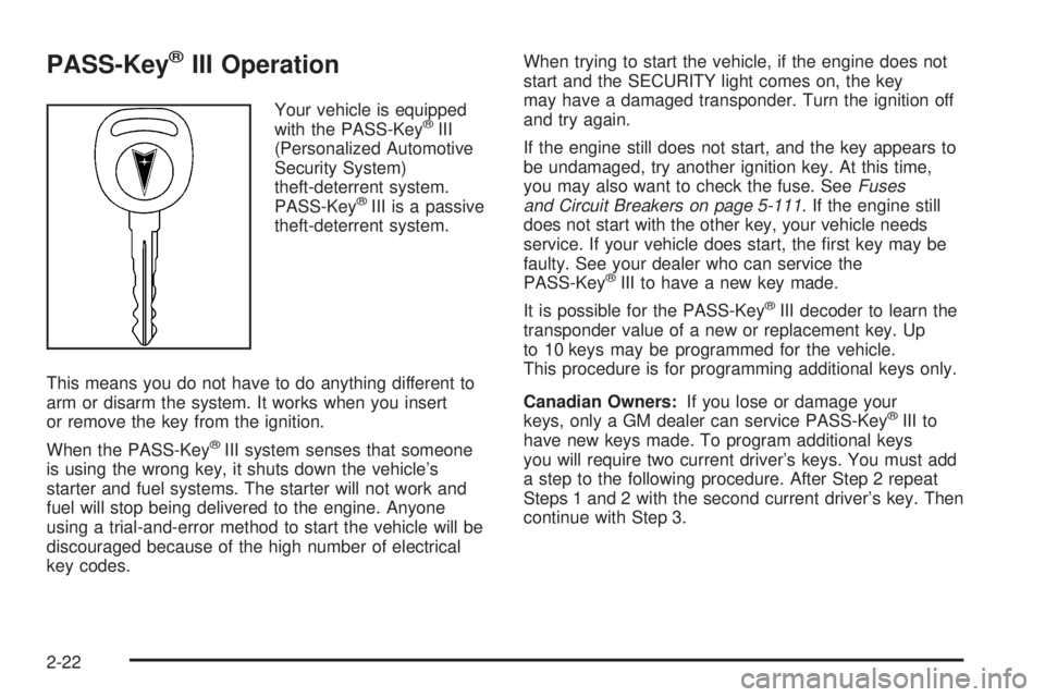
Your vehicle is equipped
with the PASS-Key®III
(Personalized Automotive
Security System)
theft-deterrent system.
PASS-Key
®III is a passive
theft-deterrent system.
This means you do not have to do anything different to
arm or disarm the system. It works when you insert
or remove the key from the ignition.
When the PASS-Key
®III system senses that someone
is using the wrong key, it shuts down the vehicle’s
starter and fuel systems. The starter will not work and
fuel will stop being delivered to the engine. Anyone
using a trial-and-error method to start the vehicle will be
discouraged because of the high number of electrical
key codes.When trying to start the vehicle, if the engine does not
start and the SECURITY light comes on, the key
may have a damaged transponder. Turn the ignition off
and try again.
If the engine still does not start, and the key appears to
be undamaged, try another ignition key. At this time,
you may also want to check the fuse. SeeFuses
and Circuit Breakers on page 5-111. If the engine still
does not start with the other key, your vehicle needs
service. If your vehicle does start, the �rst key may be
faulty. See your dealer who can service the
PASS-Key
®III to have a new key made.
It is possible for the PASS-Key
®III decoder to learn the
transponder value of a new or replacement key. Up
to 10 keys may be programmed for the vehicle.
This procedure is for programming additional keys only.
Canadian Owners:If you lose or damage your
keys, only a GM dealer can service PASS-Key
®III to
have new keys made. To program additional keys
you will require two current driver’s keys. You must add
a step to the following procedure. After Step 2 repeat
Steps 1 and 2 with the second current driver’s key. Then
continue with Step 3.
2-22
Page 120 of 438
Turn and Lane-Change Signals
The turn signal has two upward for right, and two
downward for left, positions. These positions allow you
to signal a turn or a lane change.
To signal a turn, move the lever all the way up or down.
When the turn is �nished, the lever will return
automatically.
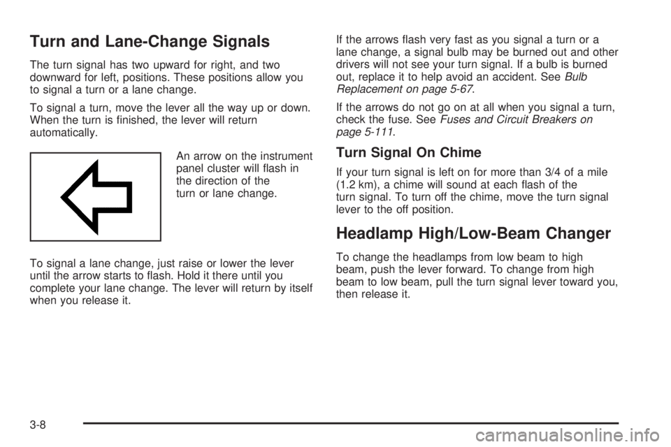
An arrow on the instrument
panel cluster will �ash in
the direction of the
turn or lane change.
To signal a lane change, just raise or lower the lever
until the arrow starts to �ash. Hold it there until you
complete your lane change. The lever will return by itself
when you release it.If the arrows �ash very fast as you signal a turn or a
lane change, a signal bulb may be burned out and other
drivers will not see your turn signal. If a bulb is burned
out, replace it to help avoid an accident. SeeBulb
Replacement on page 5-67.
If the arrows do not go on at all when you signal a turn,
check the fuse. SeeFuses and Circuit Breakers on
page 5-111.
Turn Signal On Chime
If your turn signal is left on for more than 3/4 of a mile
(1.2 km), a chime will sound at each �ash of the
turn signal. To turn off the chime, move the turn signal
lever to the off position.
Headlamp High/Low-Beam Changer
To change the headlamps from low beam to high
beam, push the lever forward. To change from high
beam to low beam, pull the turn signal lever toward you,
then release it.
3-8
Page 135 of 438
2. Adjust the seat, if necessary, before setting the
height using the IMAGE switch.
Press and hold the top of the IMAGE switch, raising
the HUD image as far as possible. Then press on
the bottom of the HUD IMAGE switch to move
the image down, so the image is as low as possible,
but in full view.
3. Turn the INTENSITY knob counterclockwise until
the HUD image is no brighter than necessary. To
turn the HUD off, turn the HUD INTENSITY knob all
the way counterclockwise.
If the sun comes out, or it becomes cloudy, or if you
turn on your headlamps, you may need to adjust
the HUD brightness using the HUD INTENSITY knob.
Polarized sunglasses could make the HUD image
harder to see.
Clean the inside of the windshield as needed to remove
any dirt or �lm that reduces the sharpness or clarity
of the HUD image.Spray household glass cleaner on a soft, clean cloth.
Wipe the HUD lens gently, then dry it. Do not spray
cleaner directly on the lens, because the cleaner �uid
could leak inside the unit.
If you cannot see the HUD image when the ignition is
on, check to see if:
The HUD unit is covered.
The HUD INTENSITY knob is adjusted correctly.
The HUD image is adjusted to the proper height.
A fuse in the fuse panel may have blown. See
Fuses and Circuit Breakers on page 5-111.
If the HUD image is not clear, it could be too bright.
Move the HUD INTENSITY knob counterclockwise. You
may need to clean the windshield and HUD lens.
Your windshield is part of the HUD system. If you ever
have to have a new windshield, be sure to get one
designed for HUD. If you do not, the HUD image may
look blurred and out of focus.
3-23
Page 262 of 438
When It Is Time for New Tires.......................5-86
Buying New Tires.........................................5-86
Uniform Tire Quality Grading..........................5-87
Wheel Alignment and Tire Balance..................5-89
Wheel Replacement......................................5-89
Tire Chains..................................................5-90
Accessory In�ator.........................................5-91
If a Tire Goes Flat........................................5-92
Changing a Flat Tire.....................................5-93
Removing the Spare Tire and Tools................5-94
Removing the Flat Tire and Installing the
Spare Tire................................................5-95
Storing a Flat or Spare Tire and Tools...........5-100
Compact Spare Tire....................................5-100
Appearance Care..........................................5-101
Fabric/Carpet..............................................5-102
Vinyl.........................................................5-103
Leather......................................................5-104
Instrument Panel.........................................5-104
Interior Plastic Components..........................5-104
Glass Surfaces...........................................5-104
Care of Safety Belts....................................5-104
Weatherstrips.............................................5-105
Washing Your Vehicle..................................5-105
Cleaning Exterior Lamps/Lenses....................5-105
Finish Care................................................5-106Windshield and Wiper Blades.......................5-106
Aluminum or Chrome-Plated Wheels..............5-107
Tires.........................................................5-107
Sheet Metal Damage...................................5-108
Finish Damage...........................................5-108
Underbody Maintenance...............................5-108
Chemical Paint Spotting...............................5-108
Vehicle Care/Appearance Materials................5-109
Vehicle Identi�cation.....................................5-110
Vehicle Identi�cation Number (VIN)................5-110
Service Parts Identi�cation Label...................5-110
Electrical System..........................................5-111
Add-On Electrical Equipment.........................5-111
Headlamp Wiring........................................5-111
Windshield Wiper Fuses...............................5-111
Power Windows and Other
Power Options........................................5-111
Fuses and Circuit Breakers..........................5-111
Engine Compartment Fuse Block
(3.8L V6 Engine).....................................5-112
Engine Compartment Fuse Block
(4.6L V8 Engine).....................................5-114
Rear Underseat Fuse Block..........................5-116
Capacities and Speci�cations........................5-121
Normal Maintenance Replacement Parts.........5-122
Section 5 Service and Appearance Care
5-2
Page 371 of 438
Electrical System
Add-On Electrical Equipment
Notice:Don’t add anything electrical to your vehicle
unless you check with your dealer �rst. Some
electrical equipment can damage your vehicle and
the damage wouldn’t be covered by your warranty.
Some add-on electrical equipment can keep other
components from working as they should.
Your vehicle has an air bag system. Before attempting to
add anything electrical to your vehicle, seeServicing
Your Airbag-Equipped Vehicle on page 1-56.
Headlamp Wiring
The headlamp wiring is protected by an internal circuit
breaker. An electrical overload will cause the lamps to
go on and off, or in some cases to remain off. If this
happens, have your headlamp system checked
right away.
Windshield Wiper Fuses
The windshield wiper motor is protected by an internal
circuit breaker and a fuse. If the motor overheats due to
heavy snow, etc., the wiper will stop until the motor
cools. If the overload is caused by some electrical
problem, have it �xed.
Power Windows and Other
Power Options
Circuit breakers in the rear fuse block protect the power
windows and other power accessories. When the
current load is too heavy, the circuit breaker opens and
closes, protecting the circuit until the problem is �xed
or goes away.
Fuses and Circuit Breakers
The wiring circuits in your vehicle are protected from
short circuits by a combination of fuses and circuit
breakers. This greatly reduces the chance of damage
caused by electrical problems.
Look at the silver-colored band inside the fuse. If the
band is broken or melted, replace the fuse. Be sure you
replace a bad fuse with a new one of the identical
size and rating.
The MaxiFuses are located in two fuse blocks, one in
the engine compartment and the other under the
rear seat. If a MaxiFuse should blow, have your vehicle
serviced by your dealer immediately.
Removing Fuses
You will �nd a fuse puller attached in both of the fuse
blocks. Snap the wide end of the fuse puller on to
the fuse at the side indentations, then hold the puller
and pull the fuse out.
5-111
Page 425 of 438
A
Accessory In�ator...........................................5-91
Accessory Power Outlets.................................3-24
Additives, Fuel................................................. 5-6
Add-On Electrical Equipment...........................5-111
Air Cleaner/Filter, Engine.........................5-22, 5-23
Air Conditioning......................................3-25, 3-28
Airbag
Readiness Light..........................................3-38
Airbag Sensing and Diagnostic Module (SDM)...... 7-9
Airbag System................................................1-47
How Does an Airbag Restrain?......................1-53
Servicing Your Airbag-Equipped Vehicle..........1-56
What Makes an Airbag In�ate?......................1-53
What Will You See After an Airbag In�ates?....1-54
When Should an Airbag In�ate?....................1-52
Where Are the Airbags?...............................1-50
Antenna, Diversity Antenna System..................3-102
Antenna, XM™ Satellite Radio Antenna System . . . 3-103
Anti-Lock Brake System (ABS)........................... 4-6
Anti-Lock Brake, System Warning Light..............3-42
Appearance Care..........................................5-101
Aluminum or Chrome-Plated Wheels.............5-107
Care of Safety Belts...................................5-104
Chemical Paint Spotting..............................5-108
Cleaning Exterior Lamps/Lenses..................5-105
Fabric/Carpet............................................5-102
Finish Care...............................................5-106Appearance Care (cont.)
Finish Damage..........................................5-108
Glass Surfaces..........................................5-104
Instrument Panel........................................5-104
Interior Plastic Components.........................5-104
Leather....................................................5-104
Sheet Metal Damage..................................5-108
Tires........................................................5-107
Underbody Maintenance.............................5-108
Vehicle Care/Appearance Materials...............5-109
Vinyl........................................................5-103
Washing Your Vehicle.................................5-105
Weatherstrips............................................5-105
Windshield and Wiper Blades......................5-106
Ashtrays........................................................3-24
Audio System(s).............................................3-72
Audio Steering Wheel Controls......................3-99
Care of Your Cassette Tape Player...............3-101
Care of Your CD Player..............................3-102
Care of Your CDs......................................3-102
Chime Level Adjustment.............................3-103
Diversity Antenna System............................3-102
Radio with Cassette and CD.........................3-83
Radio with CD............................................3-73
Setting the Time..........................................3-72
Theft-Deterrent Feature................................3-99
Trunk-Mounted CD Changer..........................3-95
Understanding Radio Reception...................3-100
XM™ Satellite Radio Antenna System...........3-103
1
Page 428 of 438
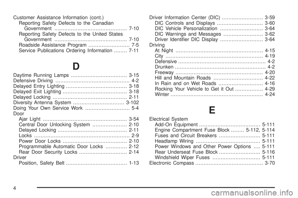
Customer Assistance Information (cont.)
Reporting Safety Defects to the Canadian
Government............................................7-10
Reporting Safety Defects to the United States
Government............................................7-10
Roadside Assistance Program......................... 7-5
Service Publications Ordering Information........7-11
D
Daytime Running Lamps..................................3-15
Defensive Driving............................................. 4-2
Delayed Entry Lighting.....................................3-18
Delayed Exit Lighting.......................................3-18
Delayed Locking.............................................2-11
Diversity Antenna System...............................3-102
Doing Your Own Service Work........................... 5-4
Door
Ajar Light...................................................3-54
Central Door Unlocking System.....................2-10
Delayed Locking..........................................2-11
Locks.......................................................... 2-9
Power Door Locks.......................................2-10
Programmable Automatic Door Locks.............2-12
Rear Door Security Locks.............................2-14
Driver
Position, Safety Belt.....................................1-13Driver Information Center (DIC).........................3-59
DIC Controls and Displays............................3-60
DIC Vehicle Personalization..........................3-64
DIC Warnings and Messages........................3-62
Driver Identi�er DIC Display..........................3-64
Driving
At Night.....................................................4-15
City...........................................................4-19
Defensive..................................................... 4-2
Drunken....................................................... 4-2
Freeway.....................................................4-20
Hill and Mountain Roads..............................4-22
In Rain and on Wet Roads...........................4-16
Rocking Your Vehicle to Get it Out.................4-29
Winter........................................................4-24
E
Electrical System
Add-On Equipment.....................................5-111
Engine Compartment Fuse Block........5-112, 5-114
Fuses and Circuit Breakers.........................5-111
Headlamp Wiring.......................................5-111
Power Windows and Other Power Options....5-111
Rear Underseat Fuse Block.........................5-116
Windshield Wiper Fuses.............................5-111
Electronic Compass.........................................3-70
4
Page 429 of 438
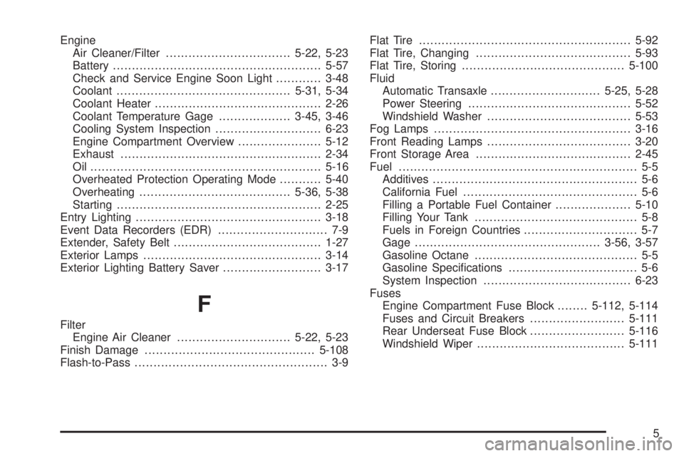
Engine
Air Cleaner/Filter.................................5-22, 5-23
Battery.......................................................5-57
Check and Service Engine Soon Light............3-48
Coolant..............................................5-31, 5-34
Coolant Heater............................................2-26
Coolant Temperature Gage...................3-45, 3-46
Cooling System Inspection............................6-23
Engine Compartment Overview......................5-12
Exhaust.....................................................2-34
Oil .............................................................5-16
Overheated Protection Operating Mode...........5-40
Overheating........................................5-36, 5-38
Starting......................................................2-25
Entry Lighting.................................................3-18
Event Data Recorders (EDR)............................. 7-9
Extender, Safety Belt.......................................1-27
Exterior Lamps...............................................3-14
Exterior Lighting Battery Saver..........................3-17
F
Filter
Engine Air Cleaner..............................5-22, 5-23
Finish Damage.............................................5-108
Flash-to-Pass................................................... 3-9Flat Tire........................................................5-92
Flat Tire, Changing.........................................5-93
Flat Tire, Storing...........................................5-100
Fluid
Automatic Transaxle.............................5-25, 5-28
Power Steering...........................................5-52
Windshield Washer......................................5-53
Fog Lamps....................................................3-16
Front Reading Lamps......................................3-20
Front Storage Area.........................................2-45
Fuel............................................................... 5-5
Additives...................................................... 5-6
California Fuel.............................................. 5-6
Filling a Portable Fuel Container....................5-10
Filling Your Tank........................................... 5-8
Fuels in Foreign Countries.............................. 5-7
Gage.................................................3-56, 3-57
Gasoline Octane........................................... 5-5
Gasoline Speci�cations.................................. 5-6
System Inspection.......................................6-23
Fuses
Engine Compartment Fuse Block........5-112, 5-114
Fuses and Circuit Breakers.........................5-111
Rear Underseat Fuse Block.........................5-116
Windshield Wiper.......................................5-111
5