sensor PONTIAC FIERO 1988 Service Repair Manual
[x] Cancel search | Manufacturer: PONTIAC, Model Year: 1988, Model line: FIERO, Model: PONTIAC FIERO 1988Pages: 1825, PDF Size: 99.44 MB
Page 728 of 1825
DRIVEABILITY AND EMISSIONS 2.8L (VIN 5) 6E3-C1-9
Install or Connect
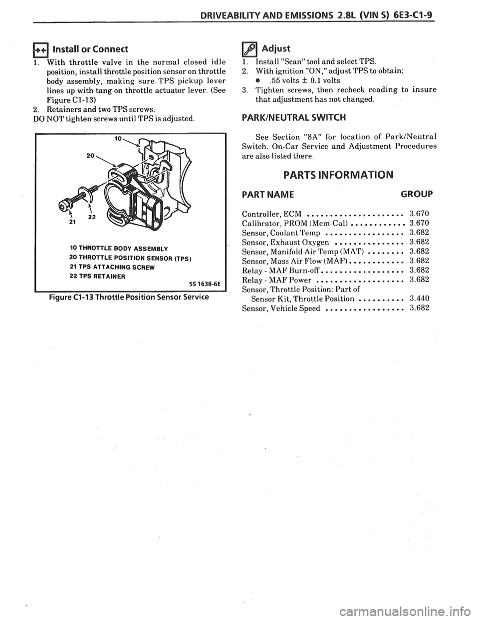
1. With throttle valve in the normal closed idle
position, install throttle position sensor on throttle
body assembly, making sure TPS pickup lever
lines up with tang on throttle actuator lever. (See
Figure
C1-13)
2. Retainers and two TPS screws.
DO NOT tighten screws until TPS is adjusted.
10 THROTTLE BODY ASSEMBLY
20 THROTTLE POSITION SENSOR (TPS)
21 TPS ATTACHING SCREW
22 TPS RETAINER
55 1638-6E
Figure C1-13 Throttle Position Sensor Service
Adjust
1. Install "Scan" tool and select TPS.
2. With ignition "ON," adjust TPS to obtain;
@ .55 volts + 0.1 volts
3. Tighten screws, then recheck reading to insure
that adjustment has not changed.
PARKINEUTRAL SWITCH
See Section "$A" for location of ParkINeutral
Switch. On-Car Service and Adjustment Procedures
are also listed there.
PARTS INFORMAION
PART NAME GROUP
..................... Controller, ECM
Calibrator, PROM
(Mem-Call ............
Sensor, Coolant Temp .................
Sensor, Exhaust Oxygen ...............
Sensor, Manifold Air Temp (MAT) ........
Sensor, Mass Air Flow (MAF). ...........
Relay - MAF Burn-off.. ................
Relay - MAF Power ...................
Sensor, Throttle Position: Part of
Sensor Kit, Throttle Position
..........
Sensor, Vehicle Speed .................
Page 736 of 1825
DRIVEABILITY AND EMISSIONS 2.8b (VIN 5) 6E3-C2-1
SECTION C2
FUEL CONTROL SYSEEIVI
CONTENTS
GENERAL DESCRIPTION . . . . . . . . . . . . . . . . C2-1 FUEL RAIL SERVICE . . . . . . . . . . . . . , . . . C2-6
PURPOSE ......................... C2-1 UNIT SERVICE PROCEDURES . . . . . . . . . . . C2-6
MODES OF OPERATION . . . . . . . . . . . . . . C2-1 COLD START TUBE & VALVE ASSEMBLY.. . C2-7
Starting Mode . . . . . . . . . . . . . . . . . . . C2-2 FUEL PRESSURE CONNECTION ASSEMBLY . C2-7
Clear Flood Mode . . . . . . . . . . . . . . . . . C2-2 FUEL BLOCK AND SEAL.. . . . . . . . . . . . . . C2-9
Run Mode .. .. . . . . . . . . . . . . . . . . . . C2-2 FUELINJECTORS .. . . . .. ... .... . . . ... C2-9
Acceleration Mode. . . . . . . . . . . . . . . . C2-2 Port Injectors wl Injector Retaining Clips C2-9
Deceleration Mode . . . . . . . . . . . . . . . C2-2 Fuel Pressure Regulator . . . . . . . . . . . . C2-10
Battery Voltage Correction Mode . . . . . C2-2 PORT INJECTORS . . . . . . . . . . . . . . . . . . . C2-10
Fuel Cutoff Mode . . . . . . . . . . . . . . . . . C2-3 PRESSURE REGULATOR.. . . . . . . . . . . . . . C2-10
Fuel Control System Components . . . . . C2-3 COLD START FUEL INJECTION SWITCH . . . C2-1 I
Basic System Operation. . . . . . . . . . . . . C2-3 THROTTLE BODY . . . . . . . . . . . . . . . . . . . C2-11
THROTTLE BODY UNIT . . . . . . . . . . . . . . . C2-3 THROTTLE BODY SERVICE IDENTIFICATION C2-11
FUEL RAIL.. . . . . . . . . . . . . . . . . . . . . . . . C2-3 MINIMUM IDLE SPEED ADJUSTMENT . . . . C2-14
FUEL INJECTOR.. . . . . . . . . . . . . . . . . . . . C2-3 UNIT REPAIR PROCEDURES . . . . . . . . . . . . C2-14
PRESSURE REGULATOR.. . . . . . . . . . . . . . C2-3 IDLE AIR CONTROL VALVE
IDLE AIR CONTROL (IAC) VALVE
. . . . . . . . C2-4 ASSEMBLY &GASKET.. . . . . . . . . . . . . . . C2-14
FUEL PUMP ELECTRICAL CIRCUIT . . . . . . . C2-4 IDLE AIRIVACUUM SIGNAL
DIAGNOSIS . . . . . . . . . . . . . . . . . . . . . . . . . C2-5 HOUSING ASSEMBLY . . . . . . . . . . . . . . . . C2-15
FUEL CONTROL SYSTEM . . . . . . . . . . . . . . C2-5 COOLANT CAVITY COVER & O-RING . . . . * C2-15
IDLE AIR CONTROL VALVE . . . . . . . . . . . . C2-5 IDLE AIR CONTROL / COOLANT
ON-CAR SERVICE . . . . . . . . . . . . . . . . . . . . . C2-5 COVERASSEMBLY .............,.... C2-16
PORT FUEL INJECTION COMPONENTS . . . . C2-5 FUEL PUMP RELAY . . . . . . . . . . . . . . . . . . C2-17
FUEL PRESSURE RELIEF PROCEDURE . . . . . C2-5 OIL PRESSURE SWITCH . . . . . . . . . . . . . . . C2-17
Plenum ........................ C2-5 PARTS INFORMATION . . . . . . . . . . . . . . . . . C2-17
Fuel Rail & Pressure Regulator Assembly . C2-5
GENERAL DESCRIPTION
PURPOSE
The basic function of the fuel control system is to
control fuel delivery to the engine.
Fuel is delivered to the engine by individual fuel
injectors mounted in the intake manifold near each
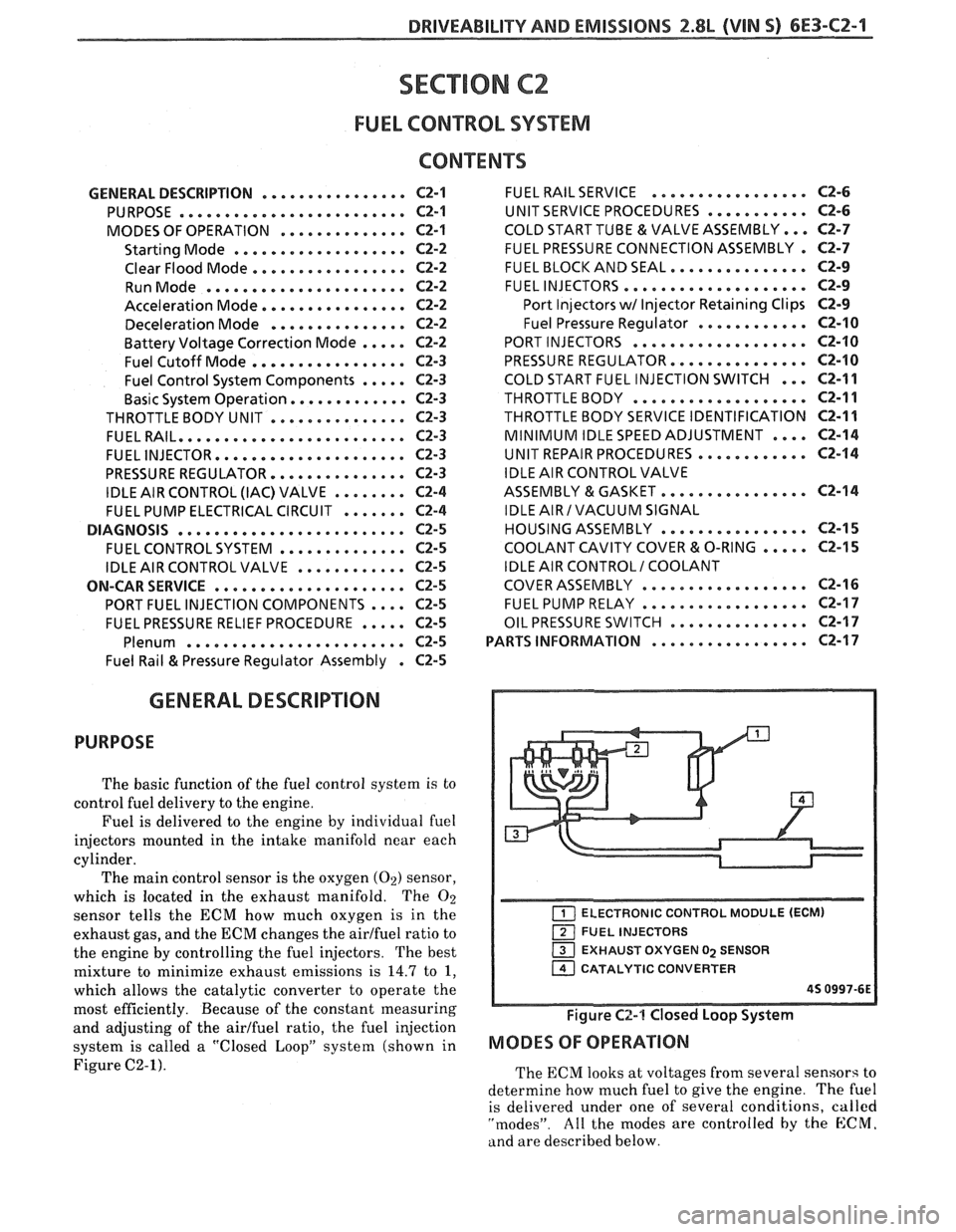
cylinder. The main control sensor is the oxygen
(02) sensor,
which is located in the exhaust manifold. The
O2
sensor tells the ECM how much oxygen is in the
exhaust gas, and the ECM changes the airlfuel ratio to
the engine by controlling the fuel injectors. The best
mixture to minimize exhaust emissions is
14.7 to 1,
which allows the catalytic converter to operate the
most efficiently. Because of the constant measuring
and adjusting of the airlfuel ratio, the fuel injection
system is called
a "Closed LoopJ' system (shown in
Figure C2-1).
ELECTRONIC CONTROL MODULE (ECM)
FUEL INJECTORS
EXHAUST OXYGEN
02 SENSOR
1 CATALYTIC CONVERTER
45 0997-6E
Figure C2-1 Closed Loop System
MODES OF OPERATION
The ECM looks at voltages from several sensors to
determine how much fuel to give the engine.
The fuel
is delivered under one of several conditions,
called
"modes". All the modes are controlled by the E:CM.
and are described below.
Page 737 of 1825
Starting Mode
When the ignition is first turned "ON," the ECM
will turn "ON" the fuel pump relay for two seconds,
and the fuel pump will build up pressure. The ECM
then checks the coolant temperature sensor, throttle
position sensor, and determines the proper airlfuel
ratio for starting. This ranges from 1.5
: 1 at -36°C (-
33°F ) to 14.7 : 1 at 94°C ( 201°F ). The ECM controls
the amount of fuel delivered in the STARTING mode
by changing how long the injectors are pulsed "ON".
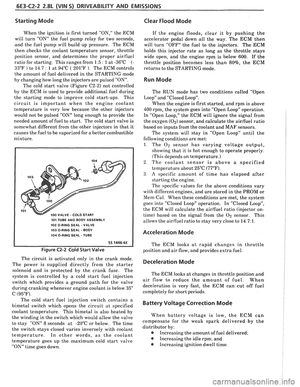
The cold start valve (Figure C2-2) not controlled
by the ECM is used to provide additional fuel during
the starting mode to improve cold start-ups. This
circuit is important when the engine coolant
temperature is very low because the other injectors
would not be pulsed "ON" long enough to provide the
needed amount of fuel to start. The cold start valve is
somewhat different from the other injectors in that it
causes the fuel to be vaporized for a better combustible
mixture.
101 TUBE AND BODY ASSEMBLY
102 O-RING SEAL
- VALVE
103 O-RING SEAL
- BODY
104 O-RING SEAL
- TUBE
Figure C2-2 Cold Start Valve
The circuit is activated only in the crank mode.
The power is supplied directly from the starter
solenoid and is protected by the crank fuse. The
system is controlled by
a cold start fuel injection
switch which provides
a ground path for the valve
during cranking whenever engine coolant is below 35"
C (95°F).
Clear Flood Mode
If the engine floods, clear it by pushing the
accelerator pedal down all the way. The
ECM then
will turn "OFF" the fuel to the injectors. The
ECM
holds this injector rate as long as the throttle stays
wide open, and the engine rpm is below
600. If the
throttle position becomes less than
80%, the ECM
returns to the STARTING mode.
Run Mode
The RUN mode has two conditions called "Open
Loop" and "Closed Loop".
When the engine is first started, and rpm is above
400 rpm, the system goes into "Open Loop" operation.
In "Open Loop," the ECM will ignore the signal from
the oxygen
(02) sensor, and calculate the airlfuel ratio
based on inputs
from the coolant and MAF sensors.
The system will stay in "Open Loop" until the
following conditions are met:
1. The
O2 sensor has varying voltage output,
showing that it is hot enough to operate properly.
(This depends on temperature.)
2. The coolant sensor is above a specified
temperature about 25°C
(77°F).
3. A specific amount of time has elapsed after
starting the engine.
The specific values for the above conditions vary
with different engines, and are stored in the PROM or
Mem-Cal. When these conditions are met, the system
goes into "Closed Loop" operation. In "Closed Loop",
the ECM will calculate the airlfuel ratio (injector on-
time) based on the signal from the
O2 sensor. This
allows the airlfuel ratio to stay very close to 14.7: 1.
Acceleration Mode
The ECM looks at rapid changes in throttle
position and air flow, and provides extra fuel.
Deceleration Mode
The ECM looks at changes in throttle position and
air flow to reduce the amount of fuel. When
deceleration is very fast, the ECM can cut off fuel
completely for short periods.
The cold start fuel injection switch contains a
bimetal switch which opens the circuit at specified
Battery Voltage Correction Mode
coolant temperature. This bimetal is also heated by
the winding in the switch which would allow the valve When battery
voltage is low, the ECM can
to stay "ON" 8 seconds at -20°C or below. The time compensate
for the weak spark delivered by the
the switch stays closed varies inversely with coolant distributor
by:
temperature. In other words, as the coolant
@ Increasing the amount of fuel delivered;
temperature goes up the maximum cold start valve
@ Increasing the idle rpm; and
"ON" time goes down. Increasing ignition
dwell time.
Page 740 of 1825
DRIVEABILITY AND EMISSIONS 2.8L (VIN 5) 6E3-C2-5
As a backup system to the fuel pump relay, the
fuel pump can also be turned "ON" by the oil pressure
switch. The oil pressure switch is a normally open
switch which closes when oil pressure reaches about
28
kPa (4 psi). If the fuel pump relay fails, the oil
pressure switch will close and run the fuel pump.
An inoperative fuel pump relay can result in long
cranking times, particularly if the engine is cold.
An inoperative fuel pump would cause a no start
condition. A fuel pump which does not provide enough
pressure can result in poor performance.
FUEL CONTROL SYSTEM
Some failures of this system will result in an
"Engine Cranks But Won't Run". If
this condition
exists, see CHART A-3. This chart will determine if
the problem is caused by the ignition system, ECM or
fuel pump circuit. If
it's determined to be a fuel
problem, CHART
A-7 will be used. This includes the
injectors, pressure regulator, fuel pump and fuel pump
relay. The fuel system wiring schematic is covered on
the facing page of Code CHART
54.
If a malfunction occurs in the fuel control system
it usually results in either a rich or a lean exhaust
condition. This condition is sensed by the oxygen
sensor and the ECM will change the fuel calculation
(injector pulse width) based on the
02 sensor reading.
The change made to the fuel calculation will be
indicated by a change in the block learn values which
can be monitored by a "Scan" tool. The normal block
learn values are around 128 and if the
O2 sensor is
sensing a lean condition, the ECM will add fuel and
this will result in a block learn value above 128. If the
02 sensor is sensing a rich exhaust the ECM will
reduce fuel to the engine and this will result in block
learn values below 128. Some variations in block
learn values are normal because all engines are not
exactly the same. However, if the block learn values
are
+ 10 counts from 128, a system problem exists. If
the block learn values are greater than 138, see Code
44 for items which can cause a lean system.
If the block learn values are less than 118, see
Code
45 for items which can cause the system to run
rich. If a driveability symptom exists, refer to the
particular symptom in Section
"B" for additional
items to check.
IDLE AIR CONTROL VALVE
A "Scan" tool will read IAC position in steps
(counts).
"0" steps indicates the ECM is commanding
the IAC to be driven all the way in, to a fully seated
position, and this is usually caused by a vacuum leak.
The higher the number of counts the more air being
allowed to pass the IAC valve. CHART C-2C can be
used to diagnosis the IAC valve. Also refer to "Rough, Unstable,
or Incorrect Idle, Stalling" in "Symptoms,"
Section
"B" for other possibilities for the cause of idle
problems.
ON-CAR SERVICE
PORT FUEL INJECTION COMPONENTS
CAUTION:
Before servicing an injector, fuel
rail, or pressure regulator, it is
necessary to relieve the pressure in
the fuel system, to minimize the risk
of fire and personal injury. (See
"Fuel Pressure Relief Procedure"
below). To reduce the chance of
personal injury, cover the fuel line
with a shop cloth to collect the fuel,
and then place the cloth in an
approved container.
FUEL PRESSURE RELIEF PROCEDURE
Connect fuel gage J 34730-1 or equivalent to fuel
pressure valve. Wrap a shop towel around fitting
while connecting gage to avoid spillage.
Install bleed hose into an approved container and
open valve to bleed system pressure.
Plenum
Remove or Disconnect
1. Negative battery cable.
2. Air
inlet duct at throttle body.
3. Throttle body retaining bolts
(2).
4. EGR pipe bolts (2).
5. Throttle cable bracket.
6. Plenum bolts (8).
Install or Connect
I. Plenum and gaskets.
2. Plenum bolts. See Figure C2-6.
3. Throttle cable bracket.
4. EGR pipe bolts.
5. Throttle body and bolts.
6. Air inlet duct
7. Negative battery cable.
Fuel Rail and Pressure Regulator Assembly
Important
When servicing the fuel rail assembly,
precautions must be taken to prevent dirt and
other contaminants from entering the fuel
passages. It is recommended that fittings
he
capped and holes be plugged during servicing.
Page 748 of 1825
DRIVEABILITY AND EMISSIONS 2.8L (VIN S) 6E3-C2-13
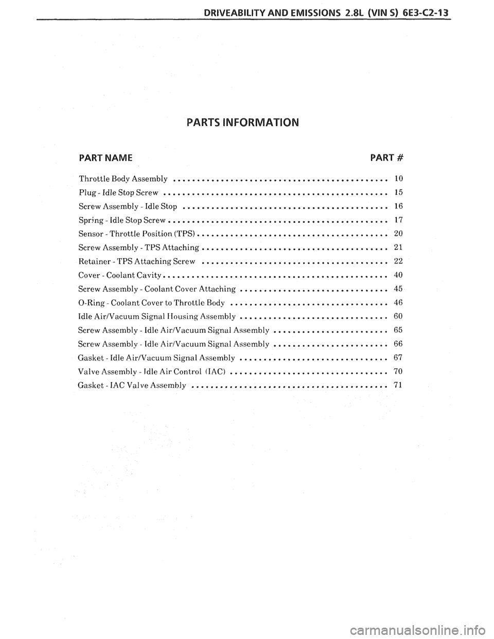
PARTS INFORMATION
PART NAME PART #
............................................. Throttle Body Assembly 10
............................................... . Plug Idle Stop Screw 15
........................................... Screw Assembly . Idle Stop 16
.............................................. . Spring
Idle Stop Screw 17
........................................ Sensor -Throttle Position (TPS) 20
....................................... Screw Assembly . TPS Attaching 21
....................................... Retainer . TPS
Attaching Screw 22
............................................... . Cover Coolant
Cavity 40
............................... Screw Assembly . Coolant Cover Attaching 45
................................. . 0-Ring
Coolant Cover to Throttle Body 46
............................... Idle AirIVacuum Signal Housing
Assembly 60
........................ Screw Assembly . Idle AirIVacuum Signal
Assembly 65
........................ Screw Assembly . Idle AirIVacuum Signal
Assembly 66
............................... . Gasket
Idle Air/Vacuum Signal Assembly 67
................................. . Valve Assembly Idle Air Control (IAC) 70
......................................... . Gasket IAC Valve Assembly 71
Page 749 of 1825
6E3-CZ-14 2.8L (VIN S) DRlVEABlLlTV AND EMISSIONS
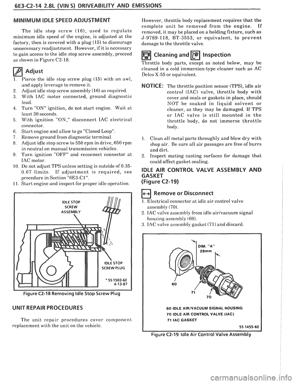
MINIMUM IDLE SPEED ADJUSTMENT
The idle stop screw (16), used to regulate
minimum idle speed of the engine, is adjusted at the
factory, then is covered with a plug
(15) to discourage
unnecessary readjustment. However,
if it is necessary
to gain access to the idle stop screw assembly, proceed
as shown in Figure C2-18.
Adjust
1. Pierce
the idle stop screw plug (15) with an awl,
and apply leverage to remove it.
2. Adjust idle
stop screw assembly (16) as required.
3. With IAC motor connected, ground diagnostic
lead.
4. Turn "ON" ignition, do not start engine. Wait at
least 30 seconds.
5. With ignition "ON," disconnect IAC electrical
connector.
6. Start engine and allow to go "Closed Loop".
7. Remove ground from diagnostic terminal.
8. Adjust idle stop screw to 550 rpm in drive, 650 rpm
in neutral on manual transmission vehicles.
9. Turn ignition "OFF7' and reconnect connector at
IAC motor.
10.
110 not adjust TPS unless setting is outside of 0.35-
0.67 limits. If adjustment is required, see
procedure in Section
"6l33-Cl".
11. Start engine and inspect for proper idle operation.
IDLE STOP
SCREW
ASSEtVIBLY
SCREW PLUG
* 55 1503-6E
Figure C2-18 Removing ldle Stop Screw Plug
UNIT REPAIR PROCEDURES
The unit repair procedures cover component
replacement with the unit on the vehicle. However,
throttle body replacement requires that the
complete unit be removed from the engine. If
removed, it may be placed on a holding fixture, such as
5-9789-118, BT-3553, or equivalent, to prevent
damage to the throttle valve.
Cleaning and Inspection
Throttle body parts, except as noted below, may be
cleaned in
a cold immersion-type cleaner such as AC
Delco X-55 or equivalent.
NOTICE: The throttle position sensor (TPS), idle air
control
(IAC) valve, throttle body with
cover and seals or gaskets in place, should
NOT be soaked in liquid solvent or
cleaner, as they may be damaged. If TPS
or IAC valve is still mounted in the
throttle body, do not immerse throttle
body.
1. Clean
all metal parts throughly and blow dry with
shop air. Be sure all air passages are free of burrs
and dirt.
2. Inspect mating casting surfaces for damage that
could affect gasket sealing.
IDLE AIR CONTROL VALVE ASSEMBLY AND
GASKET
(Figure
CZ-19)
Remove or Disconnect
1. Electrical connector at idle air control valve
assembly
(70).
2. IAC valve assembly from idle airlvacuum signal
housing assembly
(60).
3. IAC valve assembly gasket (71) and discard.
60 IDLE AIRIVACUUM SIGNAL HOUSING
70 IDLE AIR CONTROL VALVE
(IAC)
71 IAC GASKET
Figure C2-19 ldle Air Control Valve Assembly
Page 755 of 1825
6E3-C2-20 2.8L (VIN S) DRIVEABILITY AND EMISSIONS
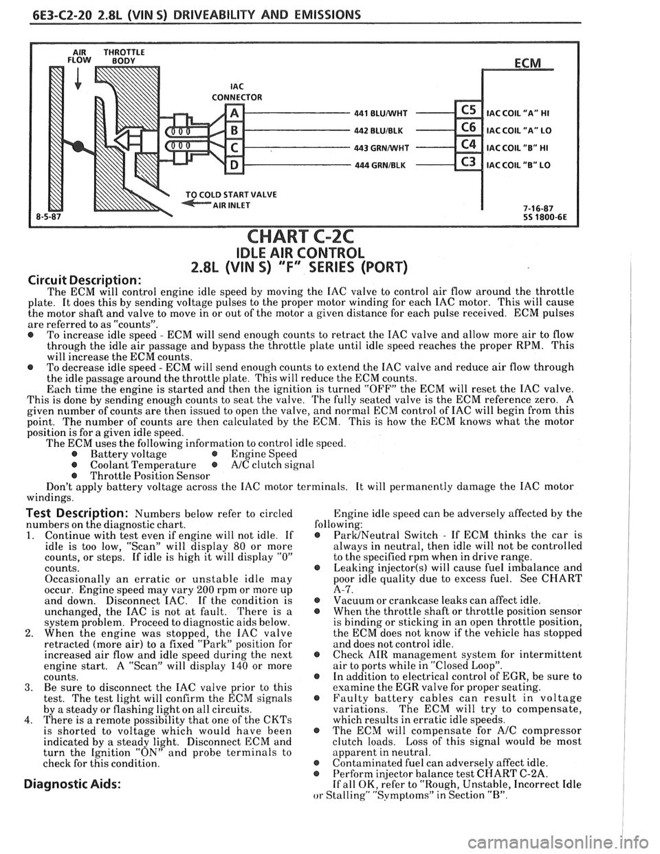
AIR THROTTLE FLOW BODY
LD START VALVE
8-5 BLUNVHT
BLUIBLK
GRMNVHT
. GRNIBLK
ECM
.
IAC COIL
"A" HI
IAC COIL "A" LO
IAC COIL "B" HI
C3 IAC COIL "B" LO
7-1 6-87
55 1800-6E
CHART C-2C
IDLE AIR CONTROL
2.8L (VIN S) ""F-SERIES (PORT)
Circuit Description:
The ECM will control engine idle speed by moving the IAC valve to control air flow around the throttle
plate. It does this by sending voltage pulses to the proper motor winding for each IAC motor. This will cause
the motor shaft and valve to move in or out of the motor a given distance for each pulse received. ECM pulses
are referred to as "counts".
@ To increase idle speed - ECM will send enough counts to retract the IAC valve and allow more air to flow
through the idle air passage and bypass the throttle plate until idle speed reaches the proper RPM. This
will increase the ECM counts.
@ To decrease idle speed - ECM will send enough counts to extend the IAC valve and reduce air flow through
the idle passage around the throttle plate. This will reduce the ECM counts.
Each time the engine is started and then the ignition is turned "OFF" the ECM will reset the IAC valve.
This is done by sending enough counts to seat the valve. The fully seated valve is the ECM reference zero. A
given number of counts are then issued to open the valve, and normal ECM control of IAC will begin from this
point. The
number of counts are then calculated by the ECM. This is how the ECM knows what the motor
position is for
a given idle speed.
The ECM uses the following information to control idle speed.
@ Battery voltage @ Engine Speed
@ Coolant Temperature @ A/C clutch signal
@ Throttle Position Sensor
Don't apply battery voltage across the IAC motor terminals. It will permanently damage the IAC motor
windings.
Test Description: Numbers below refer to circled Engine
idle speed can be adversely affected by the
numbers on the diagnostic chart. following:
1. Continue
with test even if engine will not idle. If @ ParUNeutral Switch - If ECM thinks the car is
idle is too low, "Scan" will display
80 or more always
in neutral, then idle will not be controlled
counts, or steps. If idle is high it will display
"0" to the specified rpm when in drive range.
counts.
@ Leaking injector(s) will cause fuel imbalance and
Occasionally an erratic or unstable idle may poor
idle quality due to excess fuel. See CHART
occur. Engine speed may vary
200 rpm or more up A-7.
and down. Disconnect
EAC. If the condition is @ Vacuum or crankcase leaks can affect idle.
unchanged, the IAC is not at fault. There is
a @ When the throttle shaft or throttle position sensor
system problem. Proceed to diagnostic aids below. is
binding or sticking in an open throttle position,
2. When the engine was stopped, the IAC valve the
ECM does not know if the vehicle has stopped
retracted (more air) to a fixed "Park" position for and does not control idle.
increased air flow and idle speed during the next
@ Check AIR management system for intermittent
engine start. A "Scan" will display
140 or more air
to ports while in "Closed Loop".
counts. @ In addition to electrical control of EGR, be sure to
3. Be sure to disconnect the IAC valve prior to this examine the
EGR valve for proper seating.
test. The test light will confirm the ECM signals @ Faulty battery cables can result in voltage
by a steady or flashing light on all circuits. variations. The
ECM will try to compensate,
4. There is a remote possibility that one of the CKTs which results in erratic idle speeds.
is shorted to voltage which would have been @ The ECM will compensate for A/C compressor
indicated by a steady light. Disconnect ECM and clutch
loads. Loss of this signal would be most
turn the Ignition "ON" and probe terminals to apparent
in neutral.
check for this condition.
@ Contaminated fuel can adversely affect idle. @ Perform in
or Stalling" "Svmptoms" in Section "B".
Page 765 of 1825
6E3-C4-2 2.8L (WIN S) DRIVEABILITY AND EMISSIONS
RESULTS OF INCORRECT OPERATION
An open or ground in the EST circuit will set a
Code 42 and cause the engine to run on the HE1
module timing. This will cause reduced performance
and poor fuel economy.
The ECM uses information from the
MAF and
coolant sensors in addition to rpm to calculate spark
~tdvance as follows:
@ Cold engine = more spark advance.
@ Engine under minimum load based on rpm
and low amount of air flow- more spark
advance. Hot engine
= less spark advance.
@ Engine under heavy load based on rprn and
high amount of air flow- less spark advance.
The description, operation, and diagnosis of the
HE1 system are found in Section "GD" of this manual.
CODE 12
Code 12 is used during the Diagnostic Circuit
Check procedure to test the code display ability of the
ECM. This code indicates that the ECM is not
receiving the engine
rpnl (REFERENCE) signal. This
occurs with the ignition key "ON" and the engine not
running.
The "Reference" signal also triggers the fuel
injection system. Without the "Reference" signal the
engine cannot run.
OM-CAR SERVICE
SETTING TIMING
The initial base timing is set by disconnecting the
timing connector, located near the blower motor.
Refer to Emission Control Information Label for
procedure.
This will cause Code 42 to store in the code
memory of the ECM.
The memory must be cleared
after setting timing.
How Code 42 Is Determined
When the system is running on the HE1 module,
that is no voltage on the bypass line, the
HE1 module
grounds the EST signal.
The ECk1 expects to see no
voltage
on the EST line during this condition. If it sees
a voltage, it sets code 42 and will not go into the EST
mode.
When the rpm for EST
is reachecl bout 300 rprn)
the ECM applies 5 volts to the bypass line and the E:SrI'
should no longer be grounded in the tIEI nodule so
the EST voltage should be varying.
If the bypass line is open or grounclecl, the IIEI
tnod~lle will not switch to EST mode so the EST
voltage will be low
and Code 42 will be set. Refer to
Section
"611" for on vehicle service.
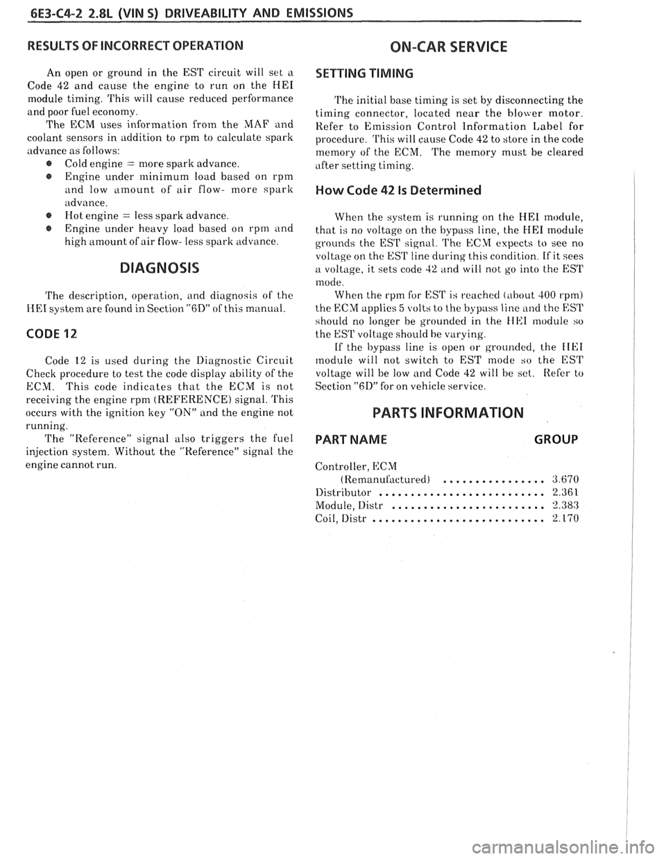
PARTS INFORMATION
PART NAME GROUP
Controller, ECM
(Remanufi~ctured) ................ 3.670
.......................... Distributor 2.36 1
Module, Distr ........................ 3.380
........................... Coil, Distr 2.170
Page 771 of 1825
6E3-C6-2 2.8L (WIN 5) DRIVEABILITY AND EMISSIONS
When the solenoid is de-energized, the pressurized
air from the air pump is allowed to enter the decel
timing chamber. This places sufficient pressure on
the metering valve diaphragm to overcome spring
tension, closing the
valve,causing air to divert to the
silencer.
At higher engine speeds, excess air is exhausted to
the silencer through the pressure relief valve. (Figure
C6-1)
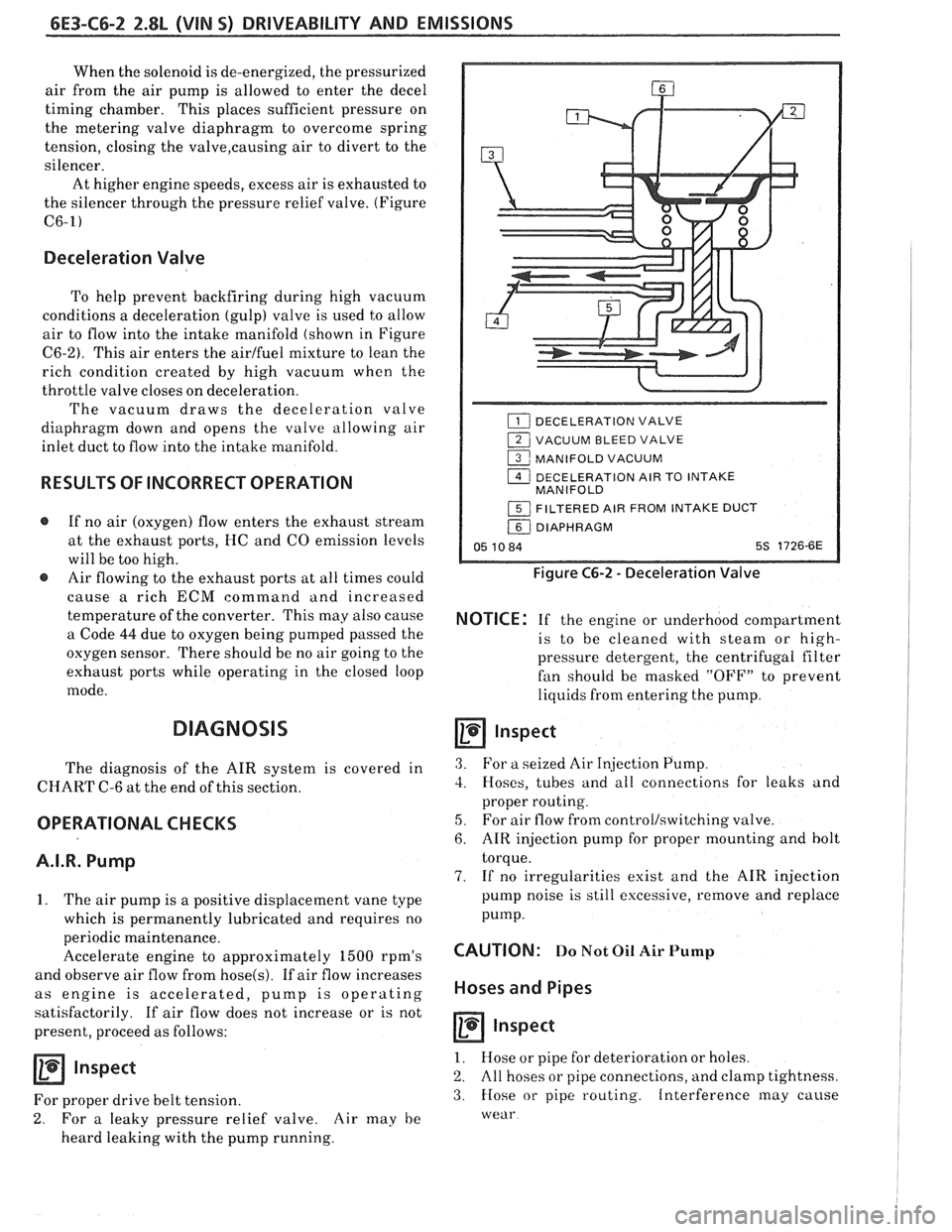
Deceleration Valve
To help prevent backfiring during high vacuum
conditions a deceleration (gulp) valve is used to allow
air to flow into the intake manifold (shown in Figure
C6-2). This air enters the airlfuel mixture to lean the
rich condition created by high vacuum when the
throttle valve closes on deceleration.
The vacuum draws the deceleration valve
diaphragm down and opens the valve allowing air
inlet duct to flow into the intake manifold.
RESULTS OF INCORRECT OPERATION
@ If no air (oxygen) flow enters the exhaust stream
at the exhaust ports, HC and
CO emission levels
will be too high.
@ Air flowing to the exhaust ports at all times could
cause
a rich ECM command and increased
temperature of the converter. This may also cause
a Code
44 due to oxygen being pumped passed the
oxygen sensor. There should be no air going to the
exhaust ports while operating in the closed loop
mode.
DIAGNOSIS
The diagnosis of the AIR system is covered in
CHART C-6 at the end of this section.
OPERATIONAL CHECKS
A.I.R. Pump
1. The air pump is a positive displacement vane type
which is permanently lubricated and requires no
periodic maintenance.
Accelerate engine to approximately
1500 rpm's
and observe air flow from
hose(s). If air flow increases
as engine is accelerated, pump is operating
satisfactorily. If air flow does not increase or is not
present, proceed as follows:
Inspect
For proper drive belt tension.
2. For a leaky pressure relief valve. Air may he
heard leaking with the pump running.
DECELERATION VALVE
1 VACUUM BLEED VALVE
1 MANIFOLD VACUUM
1 DECELERATION AIR TO INTAKE
MANIFOLD
1 FILTERED AIR FROM INTAKE DUCT
/ DIAPHRAGM
05 10 84 5s 1726-6E
Figure C6-2 - Deceleration Valve
NOTICE: If the engine or underhood compartment
is to he cleaned with
steam or high-
pressure detergent, the centrifugal filter
fan should be masked "OFF7' to prevent
liquids from entering the pump.
Inspect
3. For a seized Air Injection Pump.
3. Hoses, tubes and all connections for leaks and
proper routing.
5, For air flow from controllswitching valve.
6. AIR injection pump for proper mounting and bolt
torque.
7. If no irregularities exist and the AIR injection
pump noise is still excessive, remove and replace
pump.
CAUTION: Do Not Oil Air Pump
Hoses and Pipes
Inspect
1. Hose or pipe for deterioration or holes.
2. All hoses or pipe connections, and clamp tightness.
3. Hose or pipe routing. Interference may cause
wear
Page 778 of 1825
DRIVEABILITY AND EMISSIONS 2.8L (VIN 5) 6E3-C7-1
SECTION C7
EXHAUST GAS RECIRCULATION (EGR) SYSTEM
CONTENTS
GENERAL DESCRIPTION ................ C7-1
PURPOSE
......................... C7-1
OPERATION
....................... C7-1
ELECTRONIC VACUUM REGULATOR
VALVE
........................... C7-1
PORT EGR VALVE
................... C7-2
EGR VALVE IDENTIFICATION..
......... C7-2
RESULTS OF INCORRECT OPERATION
... C7-2
DIAGNOSIS
......................... C7-3
GENERAL DESCRIPTION
PURPOSE
The EGR system is used to lower NO, (oxides of
nitrogen) emission levels caused by high combustion
temperature. It does this
by decreasing combustion
temperature.
The main element of the system is the
EGR valve
operated by vacuum and mounted
"ON" the intake
manifold.
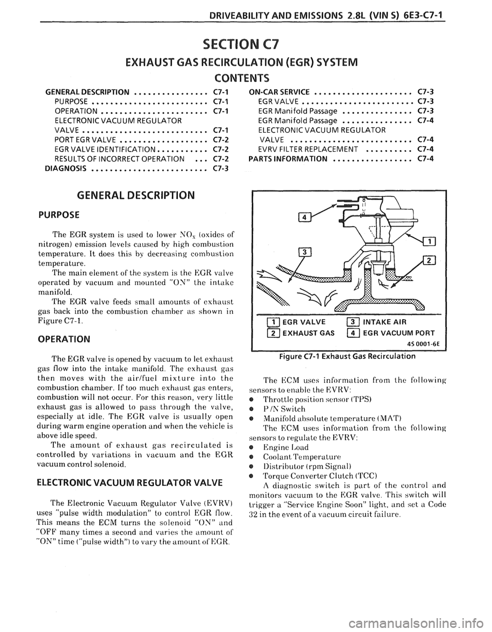
The EGR valve feeds small
amounts of exhaust
gas back into the combustion chamber as shown in
Figure C7-1.
OPERATION
..................... ON-CAR SERVICE C7-3
EGR VALVE
........................ C7-3
EGR Manifold Passage
............... C7-3
EGR Manifold Passage
............... C7-4
ELECTRONIC VACUUM REGULATOR
VALVE
.......................... C7-4
EVRV FILTER REPLACEMENT
.......... C7-4
................. PARTS INFORMATION C7-4
EGR VALVE INTAKE AIR
1 EXHAUST GAS EGR VACUUM PORT I
The EGR valve is opened by vacuum to let exhaust
gas flow into the intake manifold.
l'he exhaust gas
then moves
witb the airlfuel mixture into the
combustion chamber. If too much exhaust gas enters,
combustion will not occur. For this reason, very little
exhaust gas is allowed to pass through the valve,
especially at idle. The
EGR valve is usually open
during warm engine operation and when the vehicle is
above idle speed.
The amount of exhaust gas recirculated is
controlled by variations in vacuum and the EGR
vacuum control solenoid.
ELECTRONIC VACUUM REGULATOR VALVE
The Electronic Vacuum Regulator Valve (EVRV)
uses "pulse width modulation" to control EGK flow.
This
means the ECM turns the solenoid "ON" and
"OFF many times a second and varies the amount of
"ON" time ("pulse width") to vary the amount ot'HGK.
Figure C7-1 Exhaust Gas Recirculation
The i1:CM uses information from the following
sensors to enable the EVRV:
@ Throttle position sensor ('I'PS)
@ Plh' Switch
Manifold
ahsolute temperature (MArI')
The ECM uses information from the following
sensors to regulate the EVRV:
@ Engine 1,oad
Coolant Temperature
@ 1)istributor (rpm Signal)
@ Torque Converter Clutch (TCC)
A diagnostic switch is part of the control and
monitors vacuum to the
EGK. valve. 'I'his switch will
trigger a "Service Engine Soon" light, and set a Code
ai ure. 32 in the event of a vacuum circuit f 'I