lock PONTIAC FIERO 1988 Service Owner's Guide
[x] Cancel search | Manufacturer: PONTIAC, Model Year: 1988, Model line: FIERO, Model: PONTIAC FIERO 1988Pages: 1825, PDF Size: 99.44 MB
Page 134 of 1825
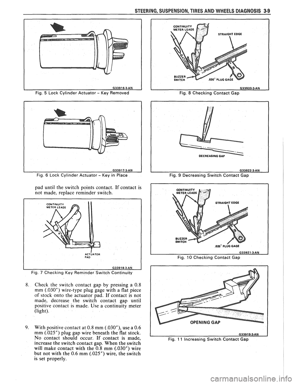
Fig. 5 Lock Cylinder Actuator - Key Removed
Fig.
6 Lock Cylinder Actuator - Key in Place
pad until the switch points contact. If contact is
not made, replace reminder switch.
I
ACTLATOR PAD
Fig. 7 Checking Key Reminder Switch Continuity
8.
Check the switch contact gap by pressing a 0.8
mm
(.03OU) wire-type plug gage with a flat piece
of stock onto the actuator pad. If contact is not
made, decrease the switch contact gap until
positive contact is made. Use a continuity meter
(light).
9. With positive contact at 0.8 mm (.03OU), use a 0.6
mm
(.025") plug gap wire beneath the flat stock.
No contact should occur.
If contact is made,
increase the switch contact gap. When the switch
will make contact with the 0.8 mm
(.030M) wire
but not with the 0.6 mm
(.025") wire, the switch
is set properly.
CONTINUITY
METERLEADS
Fig. 8 Checking Contact Gap
Fig.
9 Decreasing Switch Contact Gap
Fig.
10 Checking Contact Gap
OPENING GAP
Fig. 11 Increasing Switch Contact Gap
Page 135 of 1825
3-10 STEERING, SUSPENSION, TIRES AND WHEELS DIAGNOSIS
Reminder Keeps Operating With Key In Lock
Cylinder, Driver's Door Open Or Closed; Ceases
When Key Is Removed
Inspect
s Door jamb switch on driver's side misadjusted or
inoperative.
e Wire from signal switch to door jamb switch
shorted.
A. This condition indicates the lock cylinder or
the reminder switch is at fault. To verify,
check for continuity at the
"E" and "F"
male column connector contacts, with the
key removed from the lock cylinder. If
continuity exists, the fault is in the column.
B. Insert the key into the lock, then turn the
lock toward the "Start" position. If the
reminder stops when the key is in the
"Run" position or when it is turned past
"Run" toward "Start," the problem is a
sticky lock cylinder actuator.
COLUMN-MOUNTED DIMMER SWITCH
No "Low" or "High" Beam
Inspect
e Loose connector at dimmer switch
e Improper adjustment
e Internally damaged or worn switch. Check the
continuity on the switch at the It. green and at the
tan switch terminals by pushing in the plunger all
the way.
A click should be heard. If there is no
continuity, replace the dimmer switch. If there is
continuity, refer
to'section 8A for electricaldiag-
nosis.
PIVOT AND SWITCH ASSEMBLY
Switch Inoperative: No "Low," "High" and/or
"Wash"
e Loose body-to-switch connector
a Broken or damaged switch
Internally damaged or worn switch. Connect a
new switch without removing the old one. If the
system functions, replace the switch. If the
system doesn't function, refer to Section
8A for
electrical diagnosis.
STEERING GEAR AND PUMP LEAKS
General Procedure
Inspect
s Overfilled reservoir
s Fluid aeration and overflow
e , Hose connections
Verify exact point of leakage Example:
Torsion bar, stub shaft and
adjuster seals are close together; the exact
spot where the system is leaking may not be
clear.
Example: The point from which the fluid is
dripping is not necessarily the point where
the system is leaking; fluid overflowing from
the reservoir, for instance.
e When service is required:
A. Clean leakage area upon disassembly.
B. Replace leaking seal.
C. Check component sealing surfaces for
damage.
D. Reset bolt torque to specifications, where
required.
Some complaints about the power steering system
may be reported as:
A. Fluid leakage on garage floor
B. Fluid leaks visible on steering gear or pump
C. Growling noise, especially when parking or
when engine is cold
D. Loss of power steering when parking
E. Heavy steering effort
When troubleshooting these kinds of complaints,
check for an external leak in the power steering system.
For further diagnosis of leaks, refer to External
Leakage Check in this section.
External Leakage Check
Fig. 12
The purpose of this procedure is to pinpoint the
location of the leak.
In some cases, the leak can easily be located. But,
seepage-type leaks may be more difficult to isolate. To
locate seepage leaks, use the following method.
1. With the engine off, wipe dry the complete power
steering system.
2. Check the fluid level in the pump's reservoir. Add
fluid if necessary.
3. Start the engine, then turn the steering wheel
from stop to stop several times. Do not hold it at
a stop for any length of time, as this can damage
the power steering pump. It is easier if someone
else operates the steering wheel while you search
for the seepage.
4. Find the exact area of the leak and repair leak.
SEAL REPLACEMENT
RECOMMENDATIONS
Lip seals, which seal rotating shafts, require
special treatment. This type of seal is used on the
steering gear and on the drive shaft of the pump. When
there is a leak in one of these areas, always replace the
seal(s), after inspecting and thoroughly cleaning the
sealing surfaces. Replace the shaft only if very severe
pitting is found. If the corrosion in the lip seal contact
zone is slight, clean the surface of the shaft with crocus
cloth. Replace the shaft only if the leakage cannot be
stopped by first smoothing with crocus cloth.
Page 138 of 1825
STEERING, SUSPENSION, TIRES AND WHEELS DIAGNOSIS 3.13
in doubt about the condition, compare with a
shock known to be good.
Noisy
For struts, follow Steps 1 through 3.
1. Check all mountings for proper torque. A loose
mounting will cause a noise.
2. If all mountings are intact, bounce the car as in
Step
4 (weak) to isolate the suspected unit.
3. If practical, ride with the owner to be sure you
understand the complaint, before proceeding to
next step.
4. If one of the rear shocks is noisy, the rear axle
should be supported at least enough to unload the
shock mounts. Disconnect the lower mounting of
the suspected shock. Quickly push the shock all
the way in, then all the way out.
A hissing noise
is normal.
5. Other objectionable noises may be detected by
stroking. Any sound other
than hissing is
abnormal; replace the shock.
Leaks
1. Fully extend the strut/shocks (wheels
unsupported) to expose the seal cover area for
inspection.
2. Look for
signs of leaks in the seal cover area.
3. A slight trace of fluid is NOT cause for
replacement; the seal permits some seepage to
lubricate the piston rod. There is a built in fluid
reserve to allow for seepage.
4. A leaking strut dampener/shock can easily be
found because there will be fluid around the seal
cover and an excessive amount of fluid on the
strut
dampener/shock. A leaking strut
dampener/shock must be replaced.
BENCH CHECKS
Strut Dampeners and Regular Shock Absorbers
(Standard and Firm Ride)
Regular strut dampenerdrear shocks use a
gas-filled cell in the fluid reservoir. Aeration or
foaming of the fluid is eliminated, as the gas and the
fluid cannot mix.
Proceed with the actual bench check as follows:
1. Clamp the strut dampener/shock UPSIDE
DOWN in the vise. Do not clamp on the reservoir
tube or the mounting threads. If a lag is noticed
when it is stroked, it means the gas-filled cell has
ruptured and replacement is necessary.
2. Pump strut dampener/shock by hand at various
rates of speed and note the resistance.
3. Rebound resistance normally is stronger than
compression resistance by about 2 to 1. However,
the resistance should be smooth and constant for
each stroking rate.
4. Compare with a strut dampener/ shock known to
be good.
5. It is normal to hear a hissing noise. The following
symptoms are abnormal and are reason for
replacement. A.
A skip or lag at reversal near mid-stroke.
B. A seize (except at either extreme end of
travel).
C. A noise (such as a grunt or squeal) after
completing one full stroke in both
directions.
D. A clicking noise at fast reversal.
E. Fluid leakage.
TIRE DIAGNOSIS
Irregular and Premature Wear
Figs. 14 and 15
Irregular and premature tire wear has many
causes. Some of them are: incorrect inflation pressures,
lack of regular rotation, driving habits, or improper
wheel alignment. If wheel alignment is reset due to a
tire wear condition, always reset toe as close to zero
degrees as the specification allows.
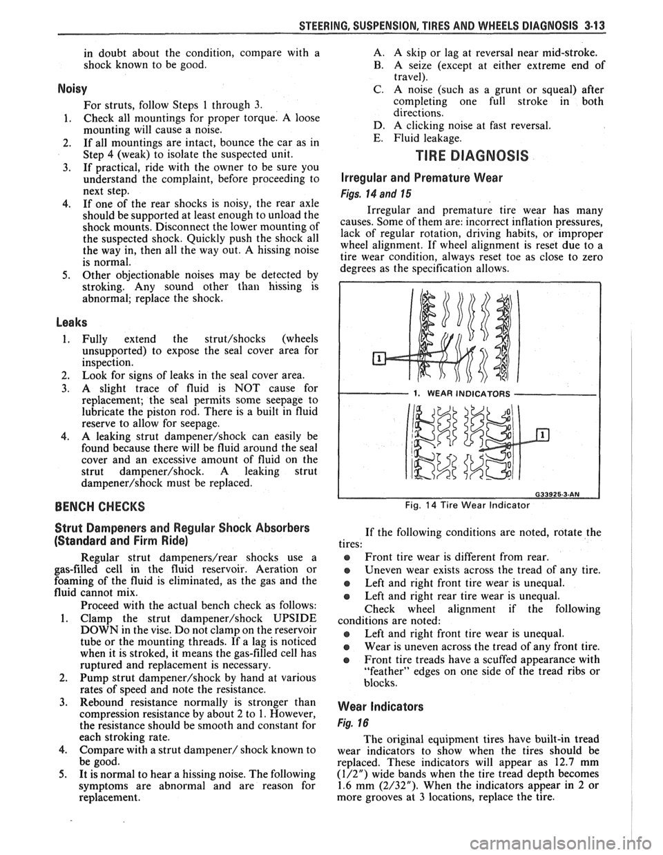
1. WEAR INDICATORS I
Fig. 14 Tire Wear Indicator
If the following conditions are noted, rotate the
tires:
@ Front tire wear is different from rear.
Uneven wear exists across the tread of any tire.
e Left and right front tire wear is unequal.
Left and right rear tire wear is unequal.
Check wheel alignment if the following
conditions are noted:
e Left and right front tire wear is unequal.
Wear is uneven across the tread of any front tire.
e Front tire treads have a scuffed appearance with
"feather" edges on one side of the tread ribs or
blocks.
Wear Indicators
Fig. 16
The original equipment tires have built-in tread
wear indicators to show when the tires should be
replaced. These indicators will appear as 12.7 mm
(1/2") wide bands when the tire tread depth becomes
1.6 mm (2/32"). When the indicators appear in 2 or
more grooves at
3 locations, replace the tire.
Page 143 of 1825
3-18 STEERING, SUSPENSION, TIRES AND WHEELS DIAGNOSIS
VIBRATION COMPLANT TIRE-WHEEL-HUB-AXLE RELATED
Vibrations that are tire or wheel induced can be caused
by two factors: imbalance or
runout. Low-speed vibrations, those less than 40 mph, are
usually runout related. Highway speed vibrations, those
above 40 mph, can be caused by either imbalance or runout. Prior to performing any work, always road test the car
and perform a careful visual inspection for:
- Obvious tire and wheel runout. - Obvious drive 'axle or propeller shaft runout. - Proper inflation pressure. - Wrong trim height. - Bent wheels. - Debris build-up on the tire or wheel. - Loose or missing wheel weights or wheel nuts. - Irregular or excessive tire wear. - Proper tire bead seating on rim. - Damaged tires, such as tread distortions,
separations, or bulges from impact damage. Slight sidewall indentations are normal and will not affect
ride quality.
Balance is the easiest procedure to perform and should,
therefore, be done fist if the vibration occurs at highway
speeds.
An off-car two-plane dynamic balance should first
be performed. This will correct any imbalance in the tire and
wheel assembly.
An oncar fiish balance may also be required. This will correct any brake drum, rotor, or wheel cover imbalance.
Follow the balancing procedures outlined in Section 3E. If balance does not correct the highway speed vibration,
or if the vibration is at low speeds, runout is the probable
cause. Runout can be caused by the tire, wheel, or the way
the wheel attaches to the car. The following procedure
should be used
: A. If runout is suspected, the free runout of the tire
and wheel assembly should first be measured on the car. A
dial indicator with a roller wheel is preferable, but a dial
indicator with button end may be used. Lateral
runout (side
to side) should be measured on the tire's sidewall as close to
the tread shoulder as possible. Radial
runout (up and down)
should be measured on the center tread rib. Some tread
designs may require tightly wrapping a piece of tape around
the center tread circumference for better dial indicator
contact. For measuring wheel
runout follow the "Measuring
Wheel Runout" procedure in Section 3E. Whether measuring
radial or lateral runout, disregard any instantaneous indicator
needle jumps due to sidewall depressions, tread blocks, etc.
Record the total indicator reading, and the location of the
high point of
runout. The,,total tire and wheel oncar runout should be less than ,060 , if either measurement exceeds ,060"~ proceed to Step B.
B. If
the oncy radial or lateral runout measured in
Step A exceeds .060 , mount the tire and wheel assembly on
a dynamic balance machine and again measure the amount of runout. Locate on the machine by the wheel's inside center
pilot hole. Using the same procedure as in Step A, record the
amount of tire and wheel
runout and its high point Location.
Next, measure wheel runout, see Section 3E. If the wheel
exceeds specifications replace the ~heel.,~If the tire and wheel
radial or lateral runout exceeds .050 at the tire tread,
proceed to Step C.
C. If the off-car tire and wheel radial or lateral runout measured in Step 18 exceeds .050", match mount the high radial runout point of tire to low radial runout point of
wheel. Weinflate, mount on the dynamic balance machine,
and again measure and record the radial and lateral runout and its location, as done in Step B. In many cases, match
mounting the tire on the wheel will bring the assembly's
runout into the acceptable range of less than .050". D. If the runout of the tire and wheel assembly is
within limits when measured off the car, yet exceeds the
limits when measured on the car, the attachment of the tire
and wheel assembly to the hub is the probable cause. Rotate
the assembly two wheel studs and recheck the
runout. Several positions may have to be tried to find the best
location.
E. If the assembly runout cannot be reduced to an
acceptable level, remove the tire and wheel assembly and
measure wheel stud
runout with a dial indicator. Zero
the dial indicator button on one stud. Lift button gently
off stud and rotate flange to position next stud against
dial indicator button. Record the
runout on all studs. Dial indicator should read zero when repositioned on first stud
that was checked. If runout exceeds .030", the hub or axle
shaft should be replaced.
Whenever a tire is rotated on the wheel, or a tire or
wheel is replaced, the assembly must be rebalanced.
In addition to balance and tire and wheel free
runout, tire stiffness variation (loaded radial runout) can also cause
a vibration. However, this is impossible to measure without
a TPD (Tire Problem Detector) or a loaded radial
runout buffer.
The TPD is a roller drum that slowly rotates the tire
while under load and mounted on the car. Tire stiffness
variation causes wheel spindle movement which can be
measured.
The loaded radial
runout buffer is a more automated
machine that slowly rotates the tire and wheel off the car
under load with a roller drum and measures the tire's
stiffness variation. It will then "match" the tire to the wheel
by buffing off small amounts of rubber from the outer tread
rows at the stiff spot. This procedure is usually effective,
especially when used
as a measuring device and for fine
buffing only.
The
TPD and loaded radial runout buffer are two
methods that will measure or correct tire stiffness variation,
tire
runout, and wheel runout at the same time. However,
because such equipment is not always available, and both
have their disadvantages, the more basic procedure of
measuring free
runout with a dial indicator, as previously
detailed, is usually more practical. The free runout of the
tire will usually correspond with the tire's stiff spot.
The substitution method of vibration diagnosis can also
be used. Install
a known good set of tire and wheel
assemblies. If these correct the vibration, the original
assemblies should be reinstalled one at
a time until the
vibration returns. This will point out the tire with excess
stiffness variation.
Tire stiffness variation will be higher or lower depending
on the direction of tire rotation.
Fig. 20 Vibration Complaint Chart (2 of 2)
Page 152 of 1825
STEERING WHEELS AND COLUMNS 385.1
SECTION 3B5
STEER NG WHEELS AND COLUMNS
NOTICE: All steering wheel and column fasteners are important attaching parts in that they could affect
the performance of vital parts and systems, and/or could result in major repair expense. They
must be replaced
with one of the same part number or with an equivalent part if
replacement becomes necessary. Do not use a
replacement part of lesser quality or substitute design. 'Torque values must be used as specified during reassembly
to assure proper retention of all parts. There is to be no welding as
it may result in extensive damage and weakening
of the metal.
For prevailing torque
nut(s) and bolts(s), refer to the "Reuse of Prevailing Torque Nut(<) and Bolt(s) " chart
in Section OA.
CONTENTS
..................... ................................................................... GENERAL DESCRIPTION .. 3B5-1 ............................................. ........................ MAINTENANCE AND ADJUSTMENTS .. 3B5-1 ON-CAR SERVICE ........................................................................................................ 3B5-2
Steering Column ............................................................................................................ 3B5-2 ......................................................................................................... Intermediateshaft 3B5-3
Park Lock Cable .................................................................... 3B54 ......................................................................................... Checking For Accident Damage 3B5-5 ............................................................................ Unit Repair Intermediate Shaft Assembly 3B5-6
..................................................................................... Standard Column @lanual Trans) 3B5-7 ......................................................... ....................... Standard Column (Auto Trans) .. 3B5-13 Tilt Column (Manual Trans) ............................................................................................. 3B5-19
Tilt Column (Auto Trans). ................................................................................................ 3B5-27
................ .................... TORQUE SPECIFICATIONS .. .. 3B5-35
SPECIAL TOOLS .......................................................................................................... 3B5-35
GENERAL DESCRIPTION
STEERING COLUMN
The function locking energy absorbing steering
column includes three important features in addition
to the steering function:
1. 'The column is energy absorbing, designed to
compress in a front-end collision to minimize the
possibility of an injury to the driver of the car.
2. The ignition switch and lock are mounted
conveniently on this column.
3. With the column mounted lock, the ignition and
steering operations can be locked to inhibit theft
of the car.
The turn signal lever provides for control of
headlight beams, windshield washer and wipers.
The column may be easily
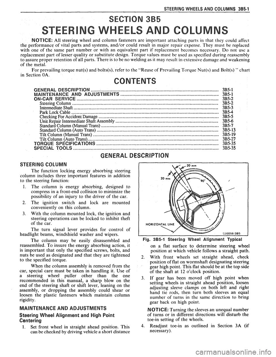
disassembled and Fig. 385-1 Steering Wheel Alignment ~ypical
reassembled. To insure the energy absorbing action, it
on a flat surface to determine steering wheel
is important that only the specified screws, bolts, and
position at which vehicle follows a straight path.
nuts be used as designated and that they are tightened
2. With front wheels set straight ahead, check to the specified torque.
position of flat on wormshaft designating steering
When the column assembly is removed from the
gear high point. This flat should be at the top side
car, special care must be taken in handling it. Use of
of the shaft at 12 o'clock position.
a steering puller other than the One 3, if gear has been moved off high when recommended in this manual, a sharp blow on the
setting wheels in straight ahead position, loosen
end of the steering shaft or shift lever, leaning on the
assembly, or dropping the assembly could shear or adjusting
sleeve clamps on both left and right
hand tie rods, then turn both sleeves an equal
loosen the plastic fasteners which maintain column
rigidity. number
of turns in the same direction
to bring
gear back
on high point.
MAINTENANCE AND ADJUSTMENTS NOTICE: Turning the sleeves an unequal number
Steering Wheel Alignment and High Point of turns or in different directions will disturb the
Centering toe-in setting of the wheels.
1. Set front wheel in straight ahead position, This 3. Readjust toe-in as outlined in Section 3A (if
can be checked by driving vehicle
a short distance necessary).
Page 153 of 1825
385-2 STEERING WHEELS AND COLUMNS
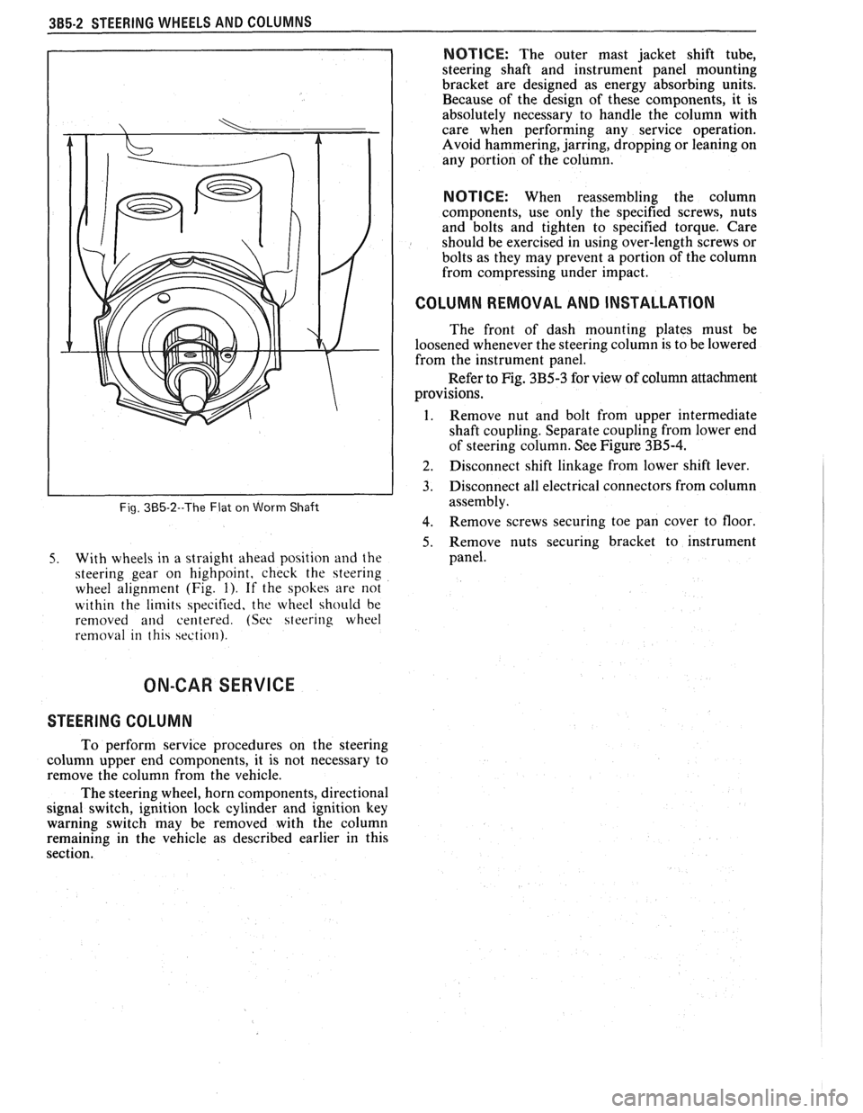
Fig. 385-2--The Flat on Worm Shaft
5. With wheels in a straight ahead position and the
steering gear on highpoint, check the steering
wheel alignment (Fig.
1). If the spokes are not
within the
limits specified, the wheel should be
removed
and centered. (See steering wheel
removal in this section).
NOTICE: The outer mast jacket shift tube,
steering shaft and instrument panel mounting
bracket are designed as energy absorbing units.
Because of the design of these components, it is
absolutely necessary to handle the column with
care when performing any service operation.
Avoid hammering, jarring, dropping or leaning on
any portion of the column.
NOTICE: When reassembling the column
components, use only the specified screws, nuts
and bolts and tighten to specified torque. Care
should be exercised in using over-length screws or
bolts as they may prevent a portion of the column
from compressing under impact.
I COLUMN REMOVAL AND INSTALLATION
The front of dash mounting plates must be
loosened whenever the steering column is to be lowered
from the instrument panel.
Refer to Fig. 3B5-3 for view of column attachment
provisions.
1. Remove nut and bolt from upper intermediate
shaft coupling. Separate coupling from lower end
of steering column. See Figure
3B5-4.
] 2. Disconnect shift linkage from lower shift lever.
3. Disconnect all electrical connectors from column
assembly.
4. Remove screws securing toe pan cover to floor
5. Remove nuts securing bracket to instrument
panel.
ON-CAR SERVICE
STEERING COLUMN
To perform service procedures on the steering
column upper end components, it is not necessary to
remove the column from the vehicle.
The steering wheel, horn components, directional
signal switch, ignition lock cylinder and ignition key
warning switch may be removed with the column
remaining in the vehicle as described earlier in this
section.
Page 155 of 1825
385-4 STEERING WHEELS AND COLUMNS
ON-CAR SERVICE
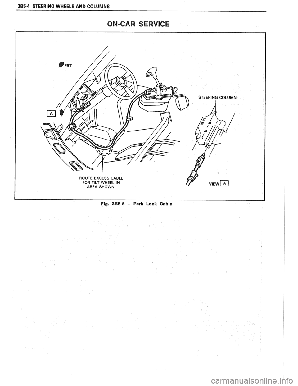
Fig. 3B5-5 -- Park Lock Cable
Page 160 of 1825
STEERING WHEELS AND COLUMNS 385-9
SUB SECTION A
INCLUDES: SHAR LOCK, TURN SIGNAL CANCELLING
CAM, UPPER BEARING SPRING, TURN SIGNAL
SWITCH,
BULZER SWITCH, AND CYLINDER LOCK SET
Tools Required:
J 23653-A Lock Plate Compressor
J 1859-03 Steering Wheel Puller
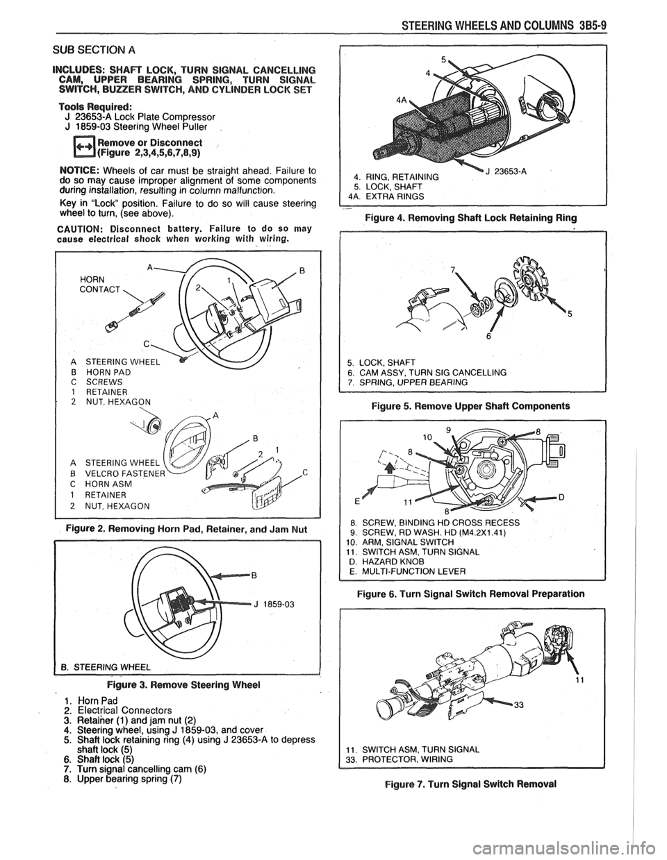
Remove or Disconnect
(Figure
2,3,4,5,6,7,8,9)
4 RING, RETAINING 5 LOCK, SHAFT
NOTICE: Wheels of car must be straight ahead. Failure to
do so may cause improper alignment of some components
during installation, resulting in column malfunction.
Key in "Lock position. Failure to do so will cause steering
- wheel to turn, (see above).
Figure 4. Removing Shaft Lock Retaining Ring
CAUTION: Disconnect battery. Failure to do so may
cause electrical
shock when working with wiring.
B HORN PAD
C SCREWS
1 RETAINER 2 NUT, HEXAGON
A STEERING WHEEL
B VELCRO FASTENE
C HORNASM
Figure 2. Removing Horn Pad, Retainer, and Jam Nut Figure
5. Remove Upper Shaft Components
8 SCREW,
BINDING HD CROSS RECESS 9. SCREW, RD WASH. HD (M4.2X1.41)
10 ARM, SIGNAL SWITCH
11 SWITCH ASM, TURN SIGNAL
D HAZARD KNOB
Figure 6. Turn Signal Switch Removal Preparation
Figure
3. Remove Steering Wheel
1. Horn Pad
2. Electrical Connectors 3. Retaiher (1) and jam nut (2) 4. Steering wheel, using J 1859-03, and cover 5. Shait lock retaining ring (4) using J 23653-A to depress
shaft lock (5)
6. Shaft lock (5) 7. Turn signal cancelling cam (6) 8. Upper bearing spring (7) Figure 7. Turn Signal Switch Removal
Page 161 of 1825
385.10 STEERING WHEELS AND COLUMNS
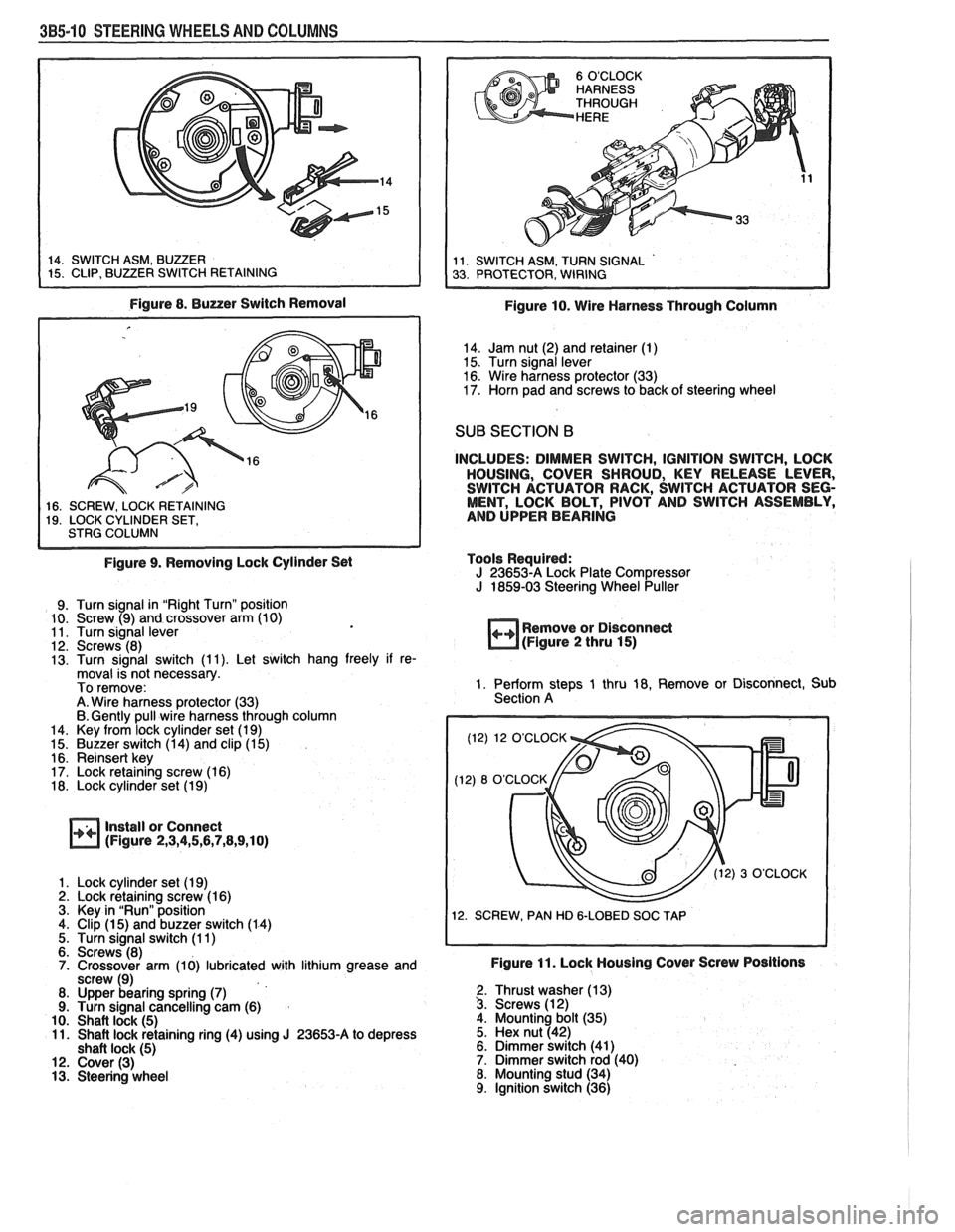
Figure 8. Buzzer Switch Removal
1 16. SCREW. LOCK RETAINING I 19. LOCK CYLINDER SET, I STRG COLUMN I
Figure 9. Removing Lock Cylinder Set
9. Turn signal in "Right Turn" position
10. Screw (9) and crossover arm (10)
11. Turn signal lever
12. Screws (8)
13. Turn signal switch (1 1). Let switch hang freely if re-
moval is not necessary.
To remove:
A. Wire harness protector (33)
6. Gently pull wire harness through column
14. Key from lock cylinder set (1 9)
15. Buzzer switch (1 4) and clip (1 5)
16. Reinsert key
17. Lock retaining screw (1 6)
18. Lock cylinder set (1 9)
Install or Connect
(Figure 2,3,4,5,6,7,8,9,10)
1. Lock cylinder set (1 9) 2. Lock retaining screw (1 6)
3. Key in "Run" position
4. Clip
(1 5) and buzzer switch (1 4)
5. Turn signal switch (1 1)
6. Screws (8)
7. Crossover arm (10) lubricated with lithium grease and
screw (9)
8. Upper bearing spring
(7) 9. Turn signal cancelling cam (6)
10. Shaft lock (5) 11. Shaft lock retaining ring (4) using J 23653-A to depress
shaft lock (5) 12. Cover (3) 13. Steering wheel
Figure 10. Wire Harness Through Column
14. Jam nut (2) and retainer (1)
15. Turn signal lever
16. Wire harness protector (33)
17. Horn pad and screws to back of steering wheel
SUB SECTION B
INCLUDES: DIMMER SWITCH, IGNITION SWITCH, LOCK
HOUSING, COVER SHROUD, KEY RELEASE LEVER,
SWITCH ACTUATOR RACK, SWITCH ACTUATOR SEG-
MENT, LOCK BOLT, PIVOT AND SWITCH ASSEMBLY,
AND UPPER BEARING
Tools Required:
J 23653-A Lock Plate Compressor J 1859-03 Steering Wheel Puller
++ Remove or Disconnect
(Figure 2 thru 15)
1. Perform steps 1 thru 18, Remove or Disconnect, Sub
Section A
(12) 12 O'CLOCK
12. SCREW, PAN HD
&LOBED SOC TAP
Figure 11. Lock Housing Cover Screw Positions
2. Thrust washer (1 3) 3. Screws (1 2)
4. Mounting bolt (35)
5. Hex nut (42)
6. Dimmer switch (41)
7. Dimmer switch rod (40)
8. Mounting stud (34)
9. Ignition switch (36)
Page 162 of 1825
STEERING WHEELS AND COLUMNS 3B5-11
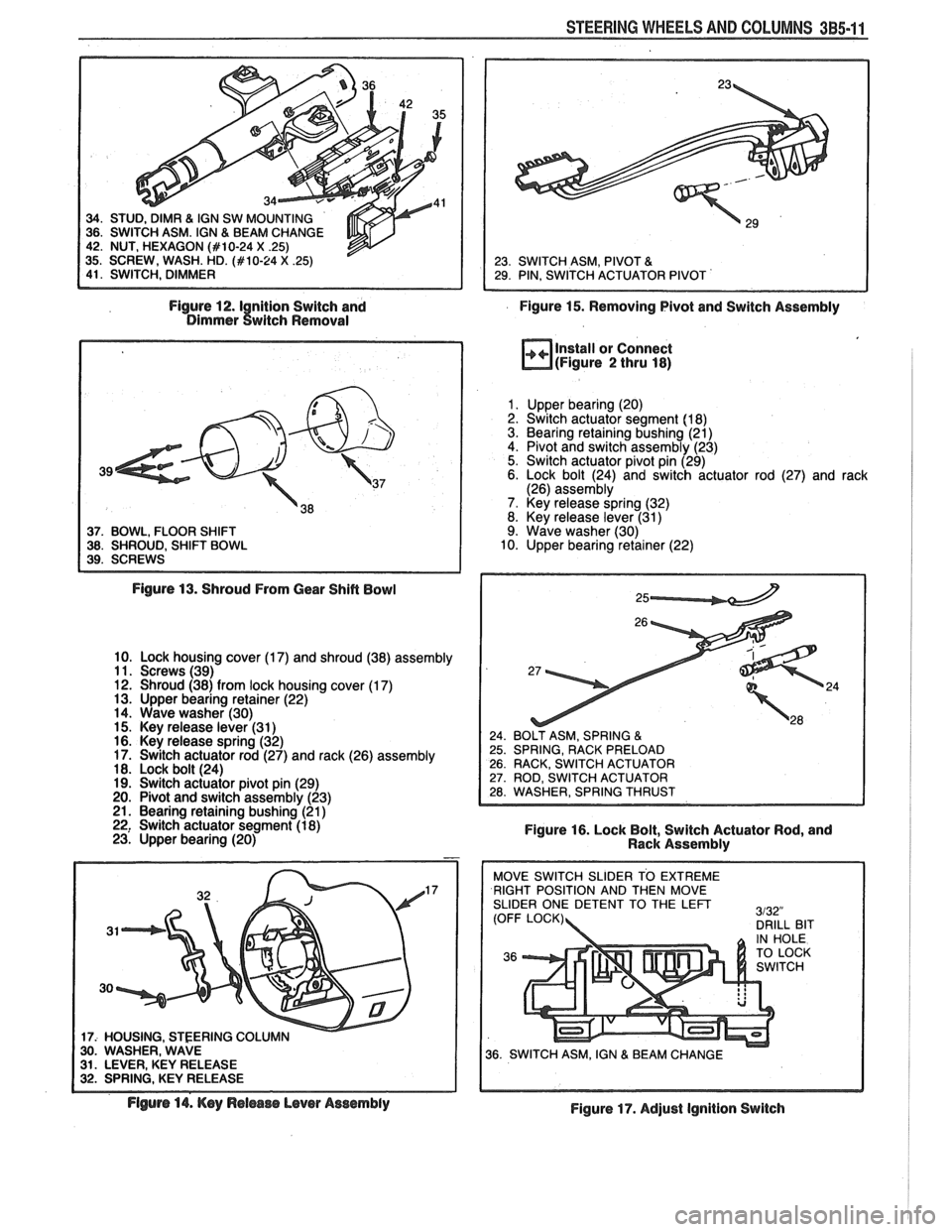
Figure 12.1 nition Switch and
Figure 15. Removing Pivot and Switch Assembly Dimmer twitch Removal
37. BOWL, FLOOR SHIFT 38. SHROUD, SHIFT BOWL
Install or Connect
(Figure 2 thru 18)
1. Upper bearing (20)
2. Switch actuator segment (1 8)
3. Bearing retaining bushing (21)
4. Pivot and switch assembly (23)
5. Switch actuator pivot pin (29)
6. Lock bolt (24) and switch actuator rod (27) and rack
(26) assembly
7. Key release spring (32)
8. Key release lever (31)
9. Wave washer (30)
10. Upper bearing retainer (22)
Figure
13. Shroud From Gear Shift Bowl
10. Lock housing cover (1 7) and shroud (38) assembly
11. Screws (39)
12. Shroud (38) from lock housing cover (1
7) 13. Upper bearing retainer (22)
14. Wave washer (30)
15. Key release lever (31
) 16. Key release spring (32)
17. Switch actuator rod (27) and rack (26) assembly
18. Lock bolt (24)
19. Switch actuator pivot pin (29)
20. Pivot and switch assembly (23)
21. Bearing retaining bushing (21
) 22, Switch actuator segment (1 8)
Figure 16. Lock Bolt, Switch Actuator Rod, and
23. Upper bearing (20)
Rack Assembly
17
17: HOUSING. STEERING COLU 30. WASHER, WAVE 31. LEVER, KEY RELEASE 32. SPRING, KEY RELEASE RIGHT
POSITION AND THEN MOVE
SLIDER ONE DETENT TO THE
LEFT
Flgurs 14. Key Release Lever Assembly
Figure 17. Adjust Ignition Switch