lights PONTIAC FIERO 1988 Service Workshop Manual
[x] Cancel search | Manufacturer: PONTIAC, Model Year: 1988, Model line: FIERO, Model: PONTIAC FIERO 1988Pages: 1825, PDF Size: 99.44 MB
Page 1335 of 1825
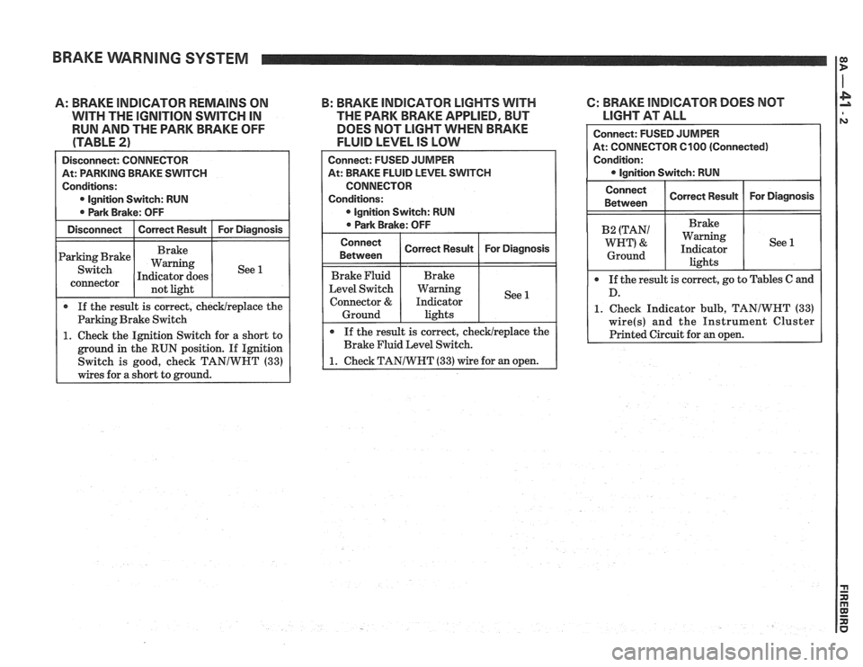
BRAKE WARNING SYSTEM I:
A: BRAKE INDICATOR REMAlNS ON
WITH THE lGNlTlON SWITCH IN
RUN AND THE PARK BRAKE OFF
(TABLE
2)
Disconnect: CONNECTOR I
At: PARKING BRAKE SWITCH
Conditions:
0 lgnition Switch: RUN
0 Park Brake: OFF
Disconnect
I Correct Result I For Diagnosis
Parking Brake
connector not light
If the result is correct, checklreplace the
Parking Brake Switch
1. Check the Ignition Switch for a short to
ground in the RUN position. If Ignition
Switch is good, check TANIWHT
(33)
wires for a short to mound.
B: BRAKE INDICATOR LIGHTS WITH 6: BRAKE INDICATOR DOES NOT
THE PARK BRAKE APPLIED, BUT
LIGHT AT ALL
DOES NOT
LIGHT WHEN BRAKE
FLUID LEVEL IS LOW
1. Check Indicator bulb, TANIWHT (33)
Connect: FUSED JUMPER
At: BRAKE FLUID LEVEL SWITCH
CONNECTOR
Conditions:
lgnition Switch: RUN
0 Park Brake: OFF
Connect
Between
Brake Fluid
Level Switch
Connector
&
Ground
If the result is correct, checklreplace the
Brake Fluid Level Switch.
1. Check TANIWHT (33) wire for an open.
Correct Result
Brake
Warning
Indicator lights
For Diagnosis
See 1
Page 1336 of 1825
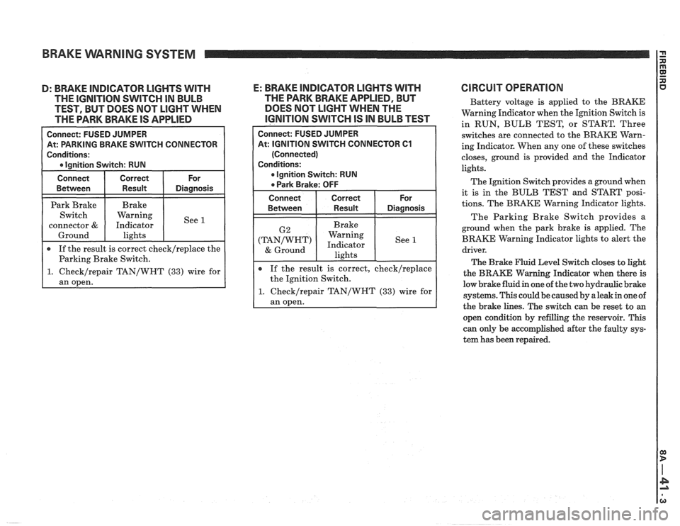
BRAKE WARNING SYSTEM
H CONNECTOR
epair TAN/WHT (33) wire for
D: BRAKE INDICATOR LIGHTS WITH E: BRAKE INDICATOR LlGHTS WITH
THE IGNITION SWITCH IN BULB THE
PARK BRAKE APPLIED, BUT
TEST, BUT DOES NOT
LIGHT WHEN DOES
NOT LIGHT WHEN THE
THE PARK BRAKE IS
APPLIED IGNITION SWITCH IS IN BULB TEST
At: IGNITION SWITCH CONNECTOR 61
If the result is correct, check/replace
the Ignition Switch.
1. Checklrepair TAN/WHT (33) wire for
ClRCUlT OPERATION
Battery voltage is applied to the BRAKE
Warning Indicator when the Ignition Switch is
in RUN, BULB TEST, or START. Three
switches are connected to the BRAKE Warn-
ing Indicator. When any one of these switches
closes, ground is provided and the Indicator
lights.
The Ignition Switch provides a ground when
it is in the BULB TEST and START posi-
tions. The BRAKE Warning Indicator lights.
The Parking Brake Switch provides a
ground when the park brake is applied. The
BRAKE Warning Indicator lights to alert the
driver.
The Brake Fluid Level Switch closes to light
the
BRAKE Warning Indicator when there is
low brake fluid in one of the two hydraulic brake
systems. This could be caused by a leak in one of
the brake lines. The switch can be reset to
an
open condition by refilling the reservoir. This
can only be accomplished after the faulty sys-
tem has been repaired.
Page 1342 of 1825
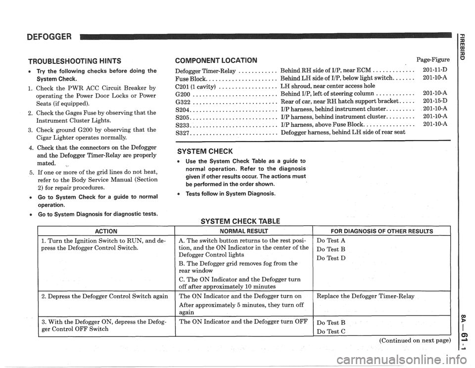
DEFOGGER
TROUBLESHOOTING HINTS
e Try the following checks before doing the
System Check.
1. Check the PWR ACC Circuit Breaker by
operating the Power Door Locks or Power
Seats (if equipped).
2. Check the Gages Fuse by observing that the
Instrument Cluster Lights.
3. Check ground 6200 by observing that the
Cigar Lighter operates normally.
4. Check that the connectors on the Defogger
and the Defogger Timer-Relay are properly
mated.
5. If one or more of the grid lines do not heat,
refer to the Body Service Manual (Section
2) for repair procedures.
e Go to System Check for a guide to normal
operation.
a Go to System Diagnosis for diagnostic tests.
COMPONENT LOCATION Page-Figure
............ ............. Defogger Timer-Relay Behind
RH side of IIP, near ECM 201-1 1-D
..................... Fuse Block. Behind LH side
of I/P, below light switch. ...... 201-10-A
.................. 6201 (1 cavity) LH
shroud, near center access hole
.......................... 6200 Behind IIP, left of steering column ............ 201-10-16
.......................... 6322 Rear of car, near RH hatch support bracket. .... 201-15-D
.......................... S204. IIP harness, behind instrument cluster. ........ 201-10-A
.......................... S205. IIP harness, behind instrument cluster. ........ 201-10-A
.......................... S233. IIP harness, above Fuse Block. ............... 201-10-A
.......................... S327. Defogger harness, behind LR side of rear seat
SYSTEM CHECK
e Use the System Check Table as a guide to
normal operation. Refer to the diagnosis
given if other results occur. The actions must
be
pedormed in the order shown.
Tests follow in System Diagnosis.
SYSTEM CHECK TABLE -- -
ACTION NORMAL RESULT FOR DIAGNOSIS OF OTHER RESULTS
1. Turn the Ignition Switch to RUN, and de-
press the Defogger Control Switch.
2. Depress the Defogger Control Switch again
3. With the Defogger ON, depress the Defog-
ger Control OFF Switch
I
A. The switch button returns to the rest posi-
tion, and the ON Indicator in the center of the
Defogger Control lights
B. The Defogger grid removes fog from the
rear window
C. The ON Indicator and the Defogger turn
off after approximately
10 minutes
The ON Indicator and the Defogger turn on
After approximately
5 minutes, they turn off
again
The ON Indicator and the Defogger turn OFF Do
Test A
Do Test B
Do Test D
Replace the Defogger Timer-Relay
Do Test B
(Continued on next page)
Page 1344 of 1825
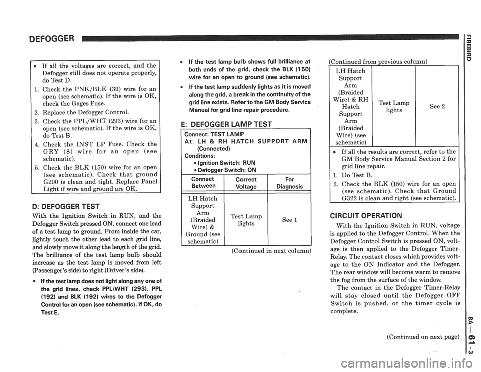
DEFOGGER
r If all the voltages are correct, and the
Defogger still does not operate properly,
do Test D.
1. Check the PNK/BLK (39) wire for an
open (see schematic). If the wire is OK,
check the Gages Fuse.
2. Replace the Defogger Control.
3. Check the PPL/WHT (293) wire for an
open (see schematic). If the wire is OK,
do Test B.
4. Check the INST LP Fuse. Check the
GRY
(8) wire for an open (see
schematic).
5. Check the BLK (150) wire for an open
(see schematic). Check that ground
6200 is clean and tight. Replace Panel
Light if wire and ground are OK.
D: DEFOGGER TEST
With the Ignition Switch in RUN, and the
Defogger Switch pressed
ON, connect one lead
of a test lamp to ground. From inside the car,
lightly touch the other lead to each grid line,
and slowly move it along the length of the grid.
The brilliance of the test lamp bulb should
increase as the test lamp is moved from left
(Passenger's side) to right (Driver's side).
0 If the test lamp does not light along any one of
the grid lines, check
PPLIWHT (2931, PPL
(192) and BLK (192) wires to the Defogger
Control for an open
(see schematic). If OK, do
Test
E.
If the test lamp bulb shows full brilliance at
both ends of the grid, check the BLK
(1 50)
wire for an open to ground (see schematic).
e If the test lamp suddenly lights as it is moved
along the grid, a break in the continuity of the
grid line exists. Refer to the
GM Body Service
Manual for grid line repair procedure.
E: DEFOGGER LAMP TEST
CH SUPPORT ARM
Ignition Switch: RUN
LH Hatch
Support Arm
(Braided Test
Lamp
lights See
1
Wire) &
Ground
(see
schematic)
(Continued in next column) (Continued
from previous column)
See 2
Arm
(Braided
Wire) (see
schematic)
I
If all the results are correct, refer to the
GM Body Service Manual Section 2 for
grid line repair.
1. Do Test B.
2. Check the BLK (150) wire for an open
(see schematic). Check that Ground
6322 is clean and tight (see schematic).
CIRCUIT OPERATION
With the Ignition Switch in RUN, voltage
is applied to the Defogger Control. When the
Defogger Control Switch is pressed ON, volt-
age is then applied to the Defogger
Timer-
Relay. The contact closes which provides volt-
age to the ON Indicator and the Defogger.
The rear window will become warm to remove
the fog from the surface of the window.
The contact in the Defogger Timer-Relay
will stay closed until the Defogger OFF
Switch is pushed, or the timer cycle is
complete.
(Continued on next page)
Page 1375 of 1825
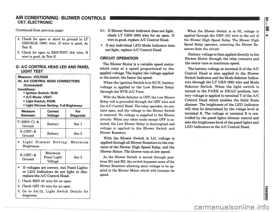
AIR CONDITIONING: BLOWER CONTROLS
C67, ELECTRONIC
(Continued from previous page)
GRNIBLK (990) wire. If wire is good, do
Test
E.
5. Check for open in BRNNHT (64) wire. If
wire is good, do Test
E.
6: A/C CONTROL HEAD LED AND PANEL
LIGHT TEST
Measure: VOLTAGE
At:
A/C CONTROL HEAD CONNECTORS
(Connected)
Conditions: Ignition Switch: RUN
@ AIC Mode: VENT
* Light Switch: PARK
Light Dimmer Setting:
Full Brightness
I (GRY) & I Battery / See 2 1 Ground
Measure
Bemeen
T (BRN) C1 &
Ground
Light Dinimer Setting: Minimum
Brightness
Correct
Voltage
Battery
If voltages are correct, but Panel Lights
or LED Indicators do not light or dim,
replace the
AlC Control Head.
1. Check BRN (9) wire for an open.
For
Diagnosis
See 1
(GRY) '
Ground
61. If Blower Switch Indicator does not light,
check LT GRN (991) wire for an open. If
wire is good, replace
AlC Control Read.
* If any individual LED Mode Indicator does
not light, replace
AlC Control Head.
CIRCUIT OPERATION
The Blower Motor is a variable speed motor
which runs at a speed proportional to the
applied voltage. The higher the voltage applied
to the motor, the faster the speed.
When the Ignition Switch is
in RUN, battery
voltage is applied to the Low Blower Relay
through the
NTR-AIC Fuse.
With the Mode Selector in OFF, the Low Blower
Relay coil is grounded through the GRY wire and
the
A/C Control Head. The relay operates, its con-
tacts open, and the voltage to the Blower Switch
is removed. No voltage is supplied to the Blower
circuits. When any other mode except OFF is se-
lected, the Low Blower Relay is deenergized and
voltage is applied to the Blower Switch and
Blower Resistors.
With the Blower Switch in LO, voltage is
applied through
all Blower Resistors to the con-
tacts of the Blower High Speed Relay, and the
Minimum
Panel Light Voltage
- -
Blower Motor. The blower runs at low speed.
As the Blower Switch is moved through posi-
tions
M1 and M2, the switch bypasses some of the
Blower Resistors allowing more voltage to be ap-
plied to the Blower Motor which will increase its
speed.
See
3
When
the Blower Switch is in HI, voltage is
applied through the ORN (52) wire to the coil of
the Blower Nigh Speed Relay. The Blower Nigh
Speed Relay operates, removing the Blower Re-
sistors from the circuit.
Battery voltage is then applied directly to the
Blower Motor through the relay contacts and
the motor runs at maximum speed.
The battery voltage at
t
Control Read is also applied to the Blower
Switch Indicator and the Mode Selector Indica-
tors through the LT GRN (991) wire and Mode
Selector Switch. When the light switch is
turned to the PARK or HEAD position, bat-
tery voltage is applied to terminal T of the
AIC
Control Head which enables the Solid State
dimmer. The brightness of the LED Indicator
will then be det
terminal R. The volt
trolled by the panel
sets the brightness level of the panel lights and
LED Indicators in the
AIC Control Head.
1 2. Check GRY (8) wire for an open. I
3. Go to 8A-12, Light Switch Details for
diagnosis.
Page 1394 of 1825
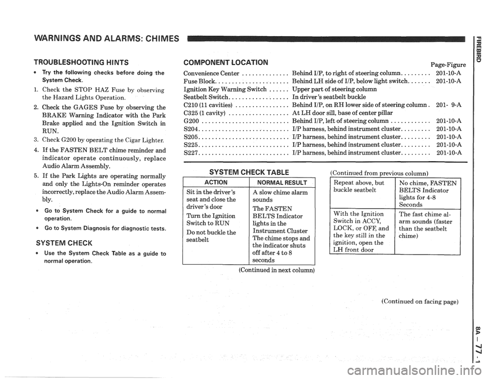
WARNINGS AND ALARMS: CHIMES
TROUBLESHOOTING H lNTS
* Try the following checks before doing the
System Check.
1. Check the STOP HAZ Fuse by observing
the Hazard Lights Operation.
2. Check the GAGES Fuse by observing the
BRAKE Warning Indicator with the Park
Brake applied and the Ignition Switch in
RUN.
3. Check 6200 by operating the Cigar Lighter.
4. If the FASTEN BELT chime reminder and
indicator operate continuously, replace
Audio Alarm Assembly.
5. If the Park Lights are operating normally
and only the Lights-On reminder operates
incorrectly, replace the Audio Alarm Assem-
bly.
Go to System Check for a guide to normal
operation.
Go to System Diagnosis for diagnostic tests.
SYSTEM CHECK
* Use the System Check Table as a guide to
normal operation.
COMPONENT LOCATlON Page-Figure
Convenience Center
.............. Behind IIP, to right of steering column. ........ 201-10-A
Fuse Block.
..................... Behind LH side of IIP, below light switch. ...... 201-10-A
Ignition Key Warning Switch
...... Upper part of steering column
Seatbelt Switch. ................. In driver's seatbelt buckle
C210
(11 cavities) ................ Behind IIP, on RH lower side of steering column. 201-
9-A
6325 (1 cavity) .................. At LH door sill, base of center pillar
6200 .......................... Behind IIP, left of steering column ............ 201-10-A
S204. .......................... IIP harness, behind instrument cluster. ........ 201-10-A
S205. .......................... IIP harness, behind instrument cluster. ........ 201-10-A
S225. .......................... I/P harness, behind instrument cluster. ........ 201-10-A
S227. .......................... IIP harness, behind instrument cluster. ........ 201-10-A
SYSTEM CHECK TABLE
ACTION
Sit in the driver's
seat and close the
driver's door
Turn the Ignition
Switch to RUN
Do not buckle the
seatbelt
NORMAL RESULT
A slow chime alarm
sounds
The FASTEN
BELTS Indicator
lights in the
Instrument Cluster
The chime stops and
the indicator shuts
off after 4 to
8
(Continued from previous column)
buckle
seatbelt
ignition, open the
LH front door
I seconds
(Continued in next column)
(Continued on facing page)
Page 1395 of 1825
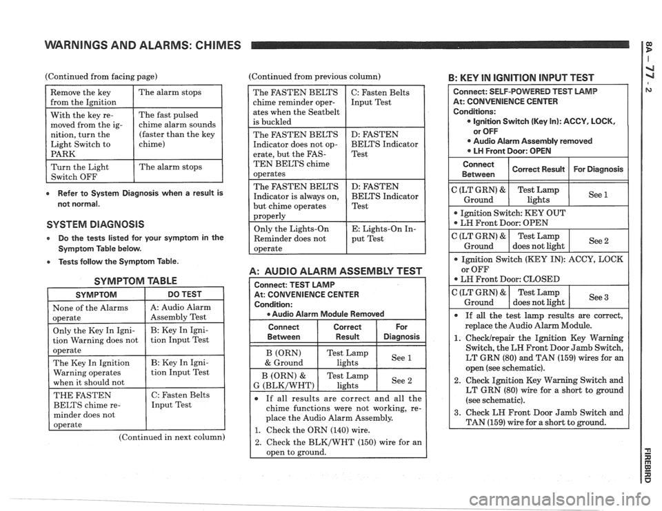
WARNINGS AND ALARMS: CHIMES I
(Continued from facing page) (Continued from previous column) B: KEY IN IGNITION INPUT TEST
e Refer to System Diagnosis when a result is
not normal.
SYSTEM DIAGNOSIS
Do the tests listed lor your symptom in the
Symptom Table below.
e Tests follow the Symptom Table.
SYMPTOM TABLE
SYMPTOM DO TEST I
1 None of the Alarms 1 A: Audio Alarm I
(Continued in next column)
A: AUDIO ALARM ASSEMBLY TEST
At: CONVENIENCE CENTER
e Audio Alarm Module Removed
The FASTEN BELTS
chime reminder oper-
ates when the
Seatbelt
is buckled
The FASTEN BELTS
Indicator does not op-
erate, but the
FAS-
TEN BELTS chime
operates
The FASTEN BELTS
Indicator is always on,
but chime operates
properly
Only the Lights-On
Reminder does not
operate
Connect Correct
Between
I Result Diasnosis
C: Fasten Belts
Input Test
D: FASTEN
BELTS Indicator
Test
D: FASTEN
BELTS Indicator
Test
E: Lights-On In-
put Test
If all results are correct and all the
chime functions were not working, re-
place the Audio Alarm Assembly.
1. Check the ORN (140) wire.
2. Check the BLK/WHT (150) wire for an
oDen to ground.
At: CONVENIENCE CENTER
LT GRN (80) and TAN (159) wires for an
open (see schematic).
2. Check Ignition Key Warning Switch and
LT GRN (80) wire for a short to ground
(see schematic).
Page 1396 of 1825
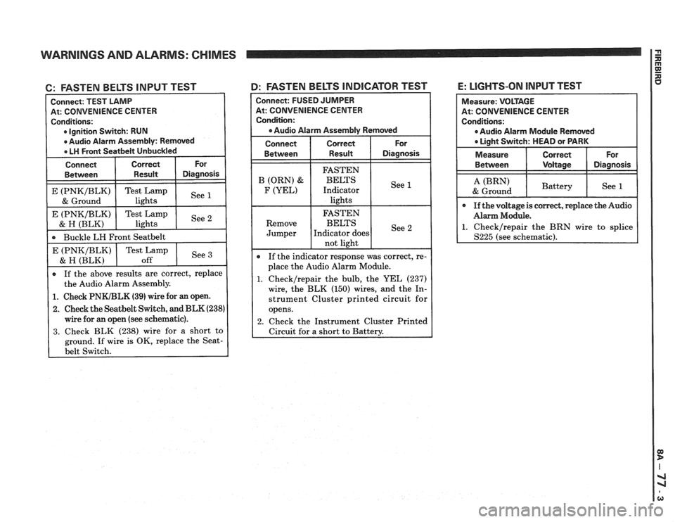
WARNINGS AND ALARMS: CHIMES
6: FASTEN BELTS INPUT TEST
At: CONVENIENCE CENTER
Ignition Switch: RUN
If the above results are correct, replace
the Audio Alarm Assembly.
Buckle
LH Front
Seatbelt
1. Check PNKIBLK (39) wire for an open.
2. Check the Seatbelt Switch, and BLK (238)
wire for an open (see schematic).
3. Check BLK (238) wire for a short to
ground. If wire is OK, replace the
Seat-
4: FASTEN BELTS INDICATOR TEST
See E (PNKIBLK)
& H (BLK)
Connect: FUSED JUMPER
At: CONVENIENCE CENTER
Condition:
a Audio Alarm Assembly Removed
Connect Correct For
Between Result Diagnosis
Test Lamp
off If
the indicator response was correct, re-
place the Audio Alarm Module.
1. Checklrepair the bulb, the YEL (237)
wire, the BLK (150) wires, and the In-
strument Cluster printed circuit for
opens.
2. Check the Instrument Cluster Printed
Circuit for
a short to Battery.
E: LIGHTS-ON INPUT TEST
At: CONVENIENCE CENTER
0 Audio Alarm Module Removed
Page 1397 of 1825
WARNINGS AND ALARMS: CHIMES
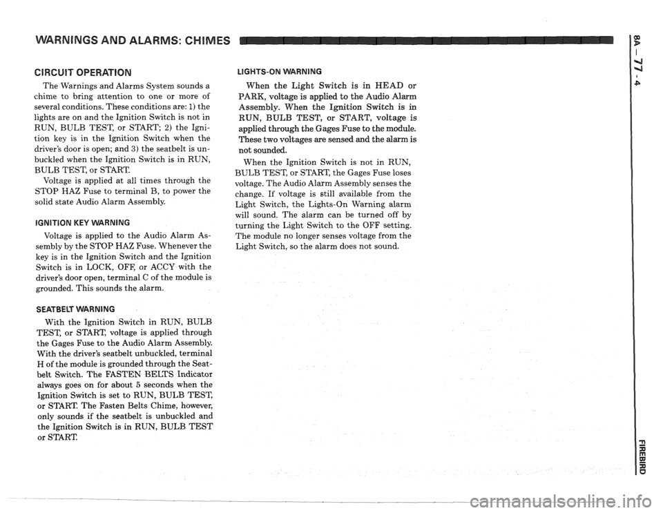
GlRGUlT OPERATION
The Warnings and Alarms System sounds a
chime to bring attention to one or more of
several conditions. These conditions are:
1) the
lights are on and the Ignition Switch is not in
RUN, BULB TEST, or START;
2) the Igni-
tion key is in the Ignition Switch when the
driver's door is open; and
3) the seatbelt is un-
buckled when the Ignition Switch is in RUN,
BULB TEST, or START.
Voltage is applied at all times through the
STOP
HAZ Fuse to terminal B, to power the
solid state Audio Alarm Assembly.
IGNITION KEY VVARNING
Voltage is applied to the Audio Alarm As-
sembly by the STOP HAZ Fuse. Whenever the
key is in the Ignition Switch and the Ignition
Switch is in LOCK, OFF, or ACCY with the
driver's door open, terminal C of the module is
grounded. This sounds the alarm.
LIGHTS-ON WARNING
When the Light Switch is in HEAD or
PARK, voltage
is applied to the Audio Alarm
Assembly. When the Ignition Switch
is in
RUN, BULB TEST, or START, voltage is
applied through the Gages Fuse to the module.
These two voltages are sensed and the alarm is
not sounded.
When the Ignition Switch is not in RUN,
BULB TEST, or START, the Gages Fuse loses
voltage. The Audio Alarm Assembly senses the
change. If voltage is still available from the
Light Switch, the Lights-On Warning alarm
will sound. The alarm can be turned off by
turning the Light Switch to the OFF setting.
The module no longer senses voltage from the
Light Switch, so the alarm does not sound.
SEATBELT WARNING
With the Ignition Switch in RUN, BULB
TEST, or START, voltage is applied through
the Gages Fuse to the Audio Alarm Assembly.
With the driver's
seatbelt unbuckled, terminal
H of the module is grounded through the Seat-
belt Switch. The FASTEN BELTS Indicator
always goes on for about
5 seconds when the
Ignition Switch is set to RUN, BULB TEST,
or START. The Fasten Belts Chime, however,
only sounds if the
seatbelt is unbuckled and
the Ignition Switch
is in RUN, BULB TEST
or START
Page 1400 of 1825
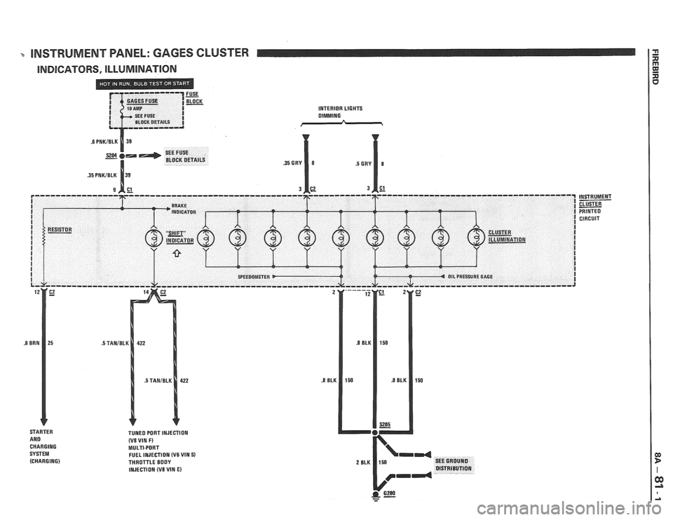
-0 INSTRUMENT PANEL: GAGES CLUSTER
INDICATORS, ILLUMINATION
INTERIOR LIGHTS DIMMING
(V8 VIN F) MULTI-PORT
FUEL INJECTION (V6 VIN S) THROTTLE BODY
INJECTION (V8 VIN E)
- -
CIRCUIT