display PONTIAC FIERO 1988 Service Repair Manual
[x] Cancel search | Manufacturer: PONTIAC, Model Year: 1988, Model line: FIERO, Model: PONTIAC FIERO 1988Pages: 1825, PDF Size: 99.44 MB
Page 499 of 1825
6E2-A-8 S.OL (VIN E) DRIVEABILITY AND EMISSIONS
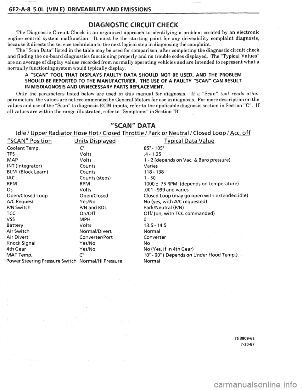
DIAGNOSmIC CIRCUIT CHECK
The Diagnostic Circuit Check is an organized approach to identifying a problem created by an electronic
engine control system malfunction. It must be the starting point for any driveability complaint diagnosis,
because it directs the service technician to the next logical step in diagnosing the complaint.
The "Scan Data" listed in the table may be used for comparison, after completing the diagnostic circuit check
and finding the on-board diagnostics functioning properly and no trouble codes displayed. The "Typical Values"
are an average of display values recorded from normally operating vehicles and are intended to represent what a
normally functioning system would typically display.
A "SCAN" TOOL THAT DISPLAYS FAULTY DATA SHOULD NOT BE USED, AND THE PROBLEM
SHOULD BE REPORTED TO THE MANUFACTURER. THE USE OF A FAULTY "SCAN" CAN RESULT
IN MISDIAGNOSIS AND UNNECESSARY PARTS REPLACEMENT.
Only the parameters listed below are used in this manual for diagnosis. If
a "Scan" tool reads other
parameters, the values are not recommended by General Motors for use in diagnosis. For more description on the
values and use of the "Scan" to diagnosis ECM inputs, refer to the applicable diagnosis section in Section
"C". If
all values are within the range illustrated, refer to "Symptoms" in Section
"B".
""SCAN" DATA
Idle / Upper Radiator Hose Hot / Closed Throttle / Park or Neutral /Closed Loop / Acc. off
"SCAN" Position Units Displayed Typical
Data Value
Coolant Temp. CO 85" - 105"
TPS Volts .4 - 1.25
MAP Volts
1 - 2 (depends on Vac. & Baro pressure)
INT (Integrator) Counts Varies
BLM (Block Learn) Counts 118- 138
IAC Counts (steps) 1-50
RPM RPM 1000
k 75 RPM (depends on temperature)
0 2 Volts .001 - 999 and varies
OpenIClosed Loop OpenICIosed Closed Loop (may go open with extended idle)
A/C Request YesINo No (yes, with A/C requested)
PIN Switch PIN and RDL
ParkINeutral (PIN)
TCC
On/Off Off1 (on, with TCC commanded)
VSS MPH 0
Battery Volts 13.5- 14.5
Air Switch NormalIDivert Normal
Air Divert ConverterIPort Converter
Knock Signal
YesINo N o
4th Gear
YesINo No (Yes, if in 4th Gear)
MAT Temp.
CO 10" - 90" ( Depends on Under Hood Temp.).
Power Steering Pressure Switch
NormalIHi Pressure Normal
Page 514 of 1825
DRIVEABILITY AND EMISSIONS 5.OL (VIN E) 6EZ-A-23
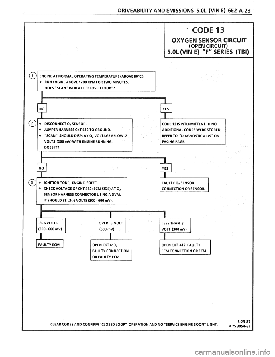
"SCAN" SHOULD DISPLAY 0, VOLTAGE BELOW -2
VOLTS (200 mV) WITH ENGINE RUNNING.
CHECK VOLTAGE OF CKT 412 (ECM SIDE) AT
O2
Page 515 of 1825
bE2-A-24 S.OL (VIN E) DRIVEABILITY AND EMlSSlONS
SENSOR GND
COD^ 14
COOLANT TEMPERATURE SENSOR CIRCUIT
(HIGH TEMPERATURE INDICATED)
5.OL (VIN E) "F"" SERIES (TBI)
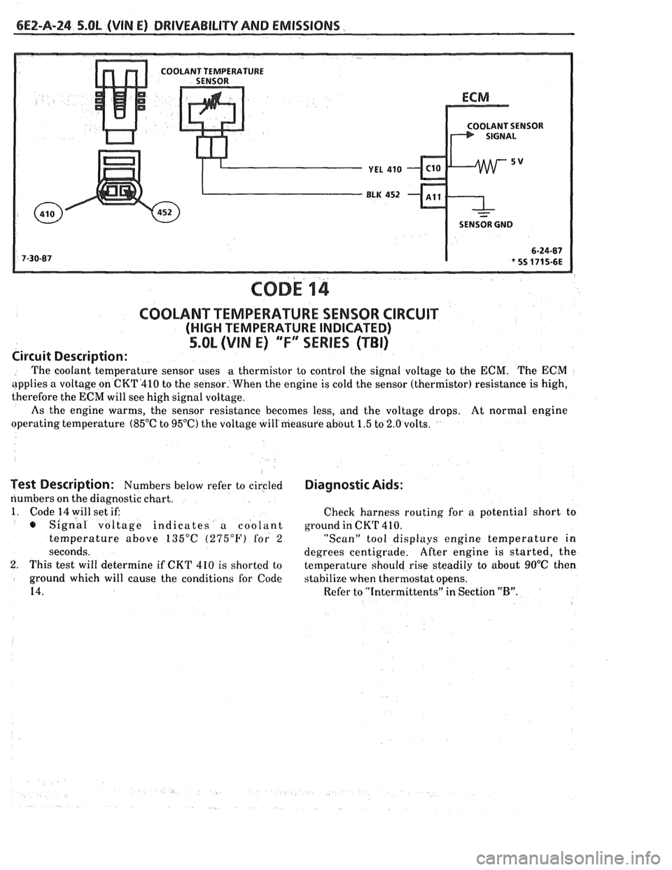
Circuit Description:
The coolant temperature sensor uses a
thermistor to control the signal voltage to the ECM. The ECM
applies a voltage on CKT4410 to the sensor. When the engine is cold the sensor (thermistor) resistance is high,
therefore the
ECM will see high signal voltage.
As the engine warms, the sensor resistance becomes less, and the voltage drops. At normal engine
operating temperature
(85°C to 95OC) the voltage will'measure about 1.5 to 2.0 volts.
Test Description: Numbers below refer to circled
numbers on the diagnostic chart.
1. Code 14 will set if:
s Signal voltage indicates a coolant
temperature above
135°C (275°F) for 2
seconds.
2. This test will determine if CKT 410 is shorted to
ground which will cause the conditions for Code
14.
Diagnostic Aids:
Check harness routing for a potential short to
ground in CKT
41 0.
"Scan" tool displays engine temperature in
degrees centigrade. After
engine is started, the
temperature should rise steadily to about
90°C then
stabilize when thermostat opens.
Refer to "Intermittents" in Section
"B".
Page 518 of 1825
DRIVEABILITY AND EMISSIONS S.OL (VIN E) 6E2-A-27
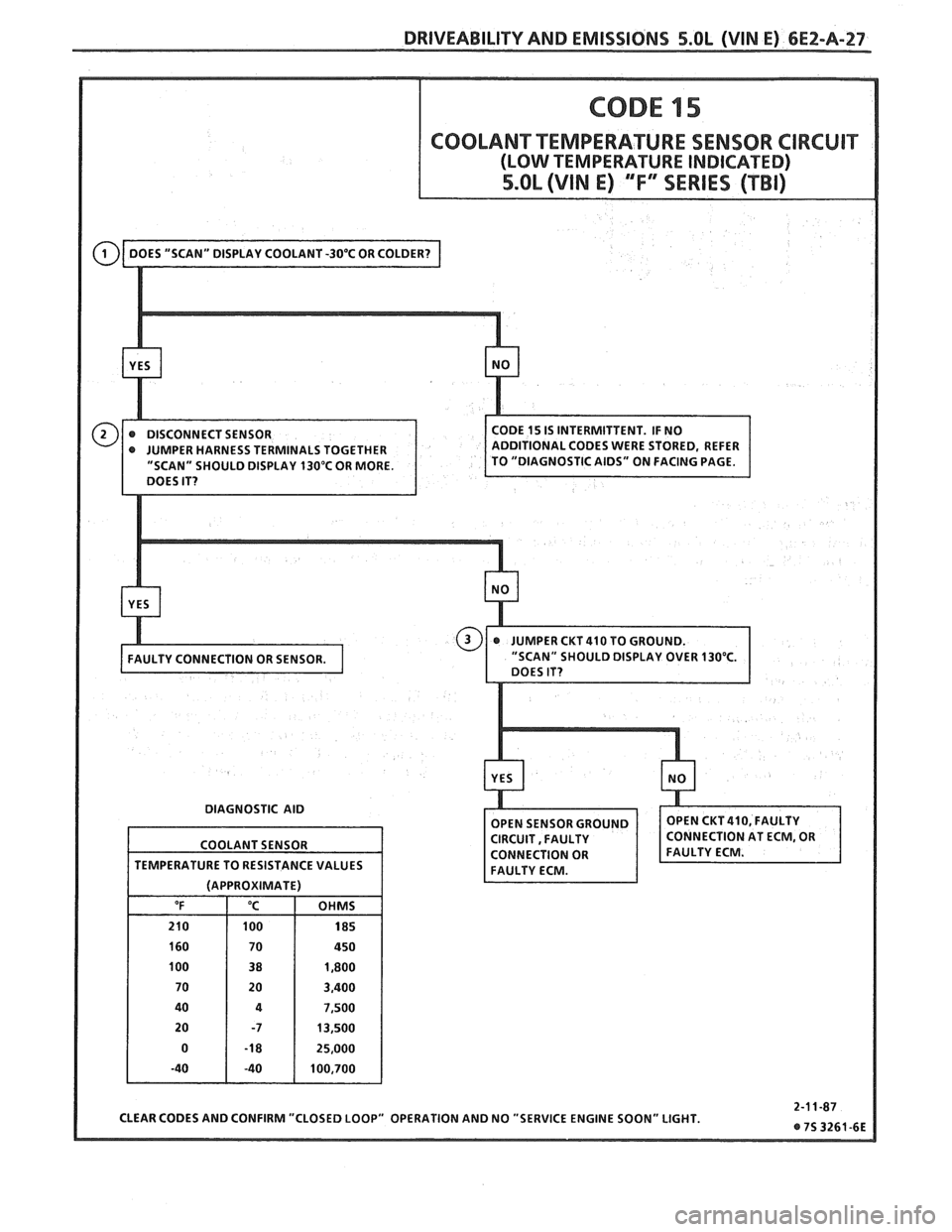
" SHOULD DISPLAY 130°C OR MORE.
DIAGNOSTIC AID
CLEAR CODES AND CONFIRM "CLOSED LOOP" OPERATION AND NO "SERVICE ENGINE SOON" LIGHT.
COOLANT
SENSOR
TEMPERATURE TO RESISTANCE VALUES
(APPROXIMATE)
"F "C OHMS
210 100 185
160 70 450
100 38 1,800
70 20 3,400
40
4 7,500
20 -7 13,500
0
-1 8 25,000
-40 -40 100,700
Page 522 of 1825
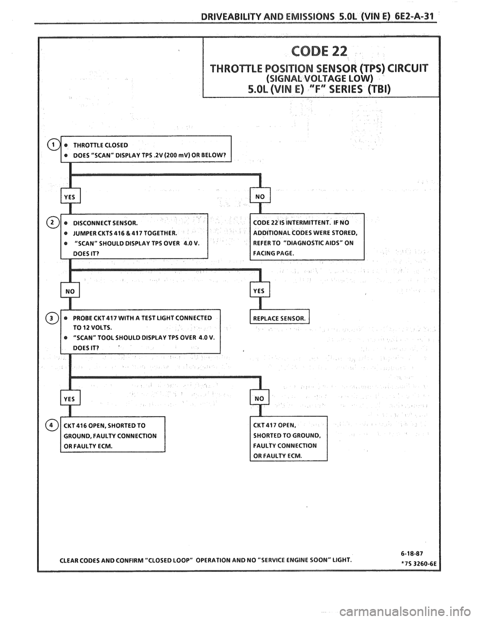
DRIVEABILITY AND EMISSIONS 5.OL (VIN E) 6EZ-A-31
THROTTLE POSITION SENSOR (TPS) CIRCUIT
ODE 22 IS INTERMITTENT. IF NO
@ JUMPER CKTS 416 & 417 TOGETHER. DDlTlONAL CODES WERE STORED,
@ "SCAN" SHOULD DISPLAY TPS OVER 4.0 V. EFER TO "DIAGNOSTIC AIDS" ON
TO
12 VOLTS.
Page 525 of 1825
6EZ-A-34 5.OL (WIN E) DRIVEABILITY AND EMISSIONS
ECM
I.P.
8RN 437
K 7 PIN SIGNAL
PIN SWITCH
r ELK450 12v
1 CLOSED IN - 15- WAY .I.P. CONNECTOR - - PARK OR NEUTRAL I
CODE 24
VEHICLE SPEED SENSOR (VSS) CIRCUIT
5.OL (VIN E) "F" SERIES (TBI)
Circuit Description:
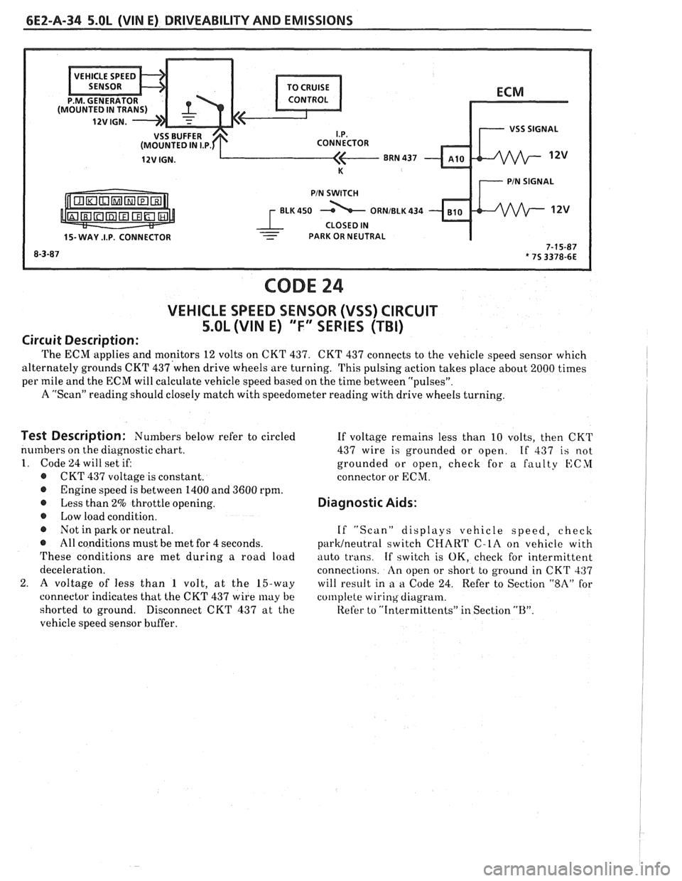
The ECM applies and monitors 12 volts on CKT 437. CKT 437 connects to the vehicle speed sensor which
alternately grounds CKT
437'when drive wheels are turning. This pulsing action takes place about 2000 times I
per mile and the ECM will calculate vehicle speed based on the time between "pulsesJ'.
A "Scan" reading should closely match with speedometer reading with drive wheels turning.
I
Test Description: Numbers below refer to circled
numbers on the diagnostic chart.
1. Code 24 will set if:
@ CKT 437 voltage is constant.
@ Engine speed is between 1400 and 3600 rpm.
@ Less than 2% throttle opening.
@ Low load condition.
@ Not in park or neutral.
@ All conditions must be met for 4 seconds.
These conditions are met during a road load
deceleration.
2.
A voltage of less than 1 volt, at the 15-way
connector indicates that the CKT 437 wire
may be
shorted to ground.
Disconnect CKT 437 at the
vehicle speed sensor buffer. If
voltage remains less than 10 volts, then CKT
437 wire is grounded or open.
If 437 is not
grounded or open, check for a faulty
KCYI
connector or ECM.
Diagnostic Aids:
If "Scan" displays vehicle speed, check
parWneutra1 switch CHART C-LA on vehicle with
auto trans.
If switch is OK, check for intermittent
connections.
An open or short to ground in CKT 437
will result in
a a Code 24. Refer to Section "$A" for
col~lplete wiring diagram.
Refer to
"[ntermittents" in Section "B".
Page 531 of 1825
6EZ-A-40 5.0L (WIN E) DRIVEABILITY AND EMISSIONS
CODE 33
MANIFOLD ABSOLUTE PRESSURE (MAP) SENSOR CIRCUIT
(SIGNAL VOLTAGE HIGH - LOW VACUUM)
5.OL (VIN E) "F" SERIES (TBI)
Circuit Description:
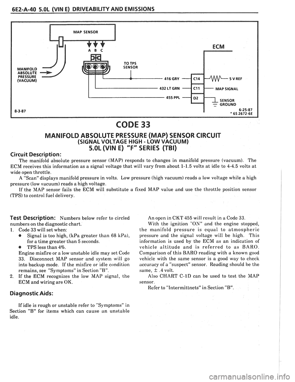
The manifold absolute pressure sensor (MAP) responds to changes in manifold pressure (vacuum). The
ECM receives this information as a signal voltage that will vary from about
1-1.5 volts at idle to 4-4.5 volts at
wide open throttle.
A "Scan" displays manifold pressure in volts. Low pressure (high vacuum) reads
a low voltage while a high
pressure (low vacuum) reads a high voltage.
If the MAP sensor fails the ECM will substitute
a fixed MAP value and use the throttle position sensor
(TPS) to control fuel delivery.
Test Description: Numbers below refer to circled
numbers on the diagnostic chart.
1. Code 33 will set when:
@ Signal is too high, (kPa greater than 68 kPa),
for a time greater than 5 seconds.
-S TPS less than 4%.
Engine misfire or a low unstable idle may set Code
33. Disconnect MAP sensor and system will go
into backup mode. If the misfire or idle condition
remains, see "Symptoms" in Section "B".
2. If the ECM recognizes the low MAP signal, the
ECM and wiring are OK.
Diagnostic Aids:
An open in CKT 455 will result in a Code 33.
With the ignition "ON" and the engine stopped,
the manifold pressure is equal to atmospheric
pressure and the signal voltage will be high.
This
information is used by the ECM as an indication of
vehicle altitude
and is referred to as BARO.
Comparison of this
BARO reading with a known good
vehicle with the same sensor is a good way to check
accuracy of a "suspect" sensor. Reading should he the
same,
& .4 volt.
Also
CHART C-lD can be used to test the MAP
sensor.
Refer to
"Intermittnets" in Section "B".
If idle is rough or unstable refer to "Symptoms" in
Section
"B" for items which can cause an unstable
idle.
Page 533 of 1825
6EZ-A-42 5.OL (VIN E) DRIVEABILITY AND EMISSIONS
CODE 34
MANIFOLD ABSOLUTE PRESSURE (MAP) SENSOR CIRCUIT
(SIGNAL VOLTAGE LOW - HIGH VACUUM)
5.OL (VIN E) ""F-SERlES (TBI)
Circuit Description:
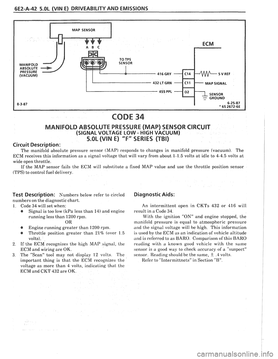
The manifold absolute pressure sensor (MAP) responds to changes in manifold pressure (vacuum). The
ECM receives this information as a signal voltage that will vary from about 1-1.5 volts at idle to 4-4.5 volts at
wide open throttle.
If the MAP sensor fails the ECM will substitute a fixed MAP value and use the throttle position sensor
(TPS) to control fuel delivery.
Test Description: Numbers below refer to circled
numbers on the diagnostic chart.
1. Code 34 will set when:
e Signal is too low (kPa less than 14) and engine
running less than 1200 rpm.
OR
@ Engine running greater than 1200 rpm.
e Throttle position greater than 21% (over 1 5
volts).
2. If
the ECM recognizes the high hIAP signal, the
ECM and wiring are OK.
3. The "Scan" tool may not display 12 volts. The
important thing is that the ECM recognizes the
voltage as more than 4 volts, indicating that tho
ECM and CKT 432 are OK.
Diagnostic Aids:
An intermittent open in CKTs 432 or 416 will
result in a Code 34.
With the ignition "ON" and engine stopped, the
manifold pressure is equal to atmospheric pressure
and the signal voltage will be high. This information
is
used by the ECM as an indication of vehicle altitude
and is referred to as BARO. Comparison of this BARO
reading with a known good vehicle wilh the same
sensor is a good way to check accuracy of a "suspect"
sensor.
Iteading shoulci be the same, + .4 volts.
Refer to "Intermittnets" in Section "B".
Page 537 of 1825
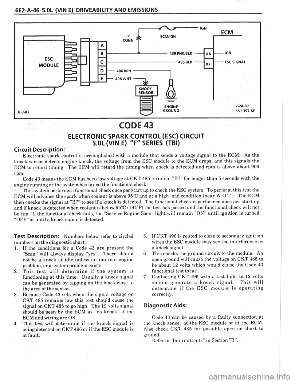
CODE 43
ELECTRONIC SPARK CONTROL (ESC) CIRCUIT
5.0L (VIN E) "F" SERIES (TBI)
Circuit Description:
Electronic spark control is accomplished with a module that sends a voltage signal to the ECM. As the
knock sensor detects engine knock, the voltage from the ESC module to the ECM drops, and this signals the
ECM to retard timing. The ECM will retard the timing when knock is detected and rpm is above about 900
rpm. Code 43 means the ECM has been low voltage at CKT 485 terminal
"B7" for longer than 5 seconds with the
engine running or the system has failed the functional check.
This system performs a functional check once per start up to check the ESC system. To perform this test the
ECM will advance the spark when coolant is above 95°C and at
a high load condition (near W.O.T.). The ECM
then checks the signal at
"B7" to see if a knock is detected. The functional check is performed once per start up
and if knock is detected when coolant is below 95°C (194°F) the test has passed and the functional check will not
be run. If the functional check fails, the "Service Engine Soon" light will
remain "ON" until ignition is turned
"OFF" or until a knock signal is detected.
Test Description: Numbers below refer to circled
numbers on the diagnostic chart.
1. If the conditions for a Code 43 are present the
"Scan" will always display "yes". There should
not be a knock at idle unless an internal engine
problem, or a system problem exists.
2. This test will determine if the system is
functioning at this time. Usually a
knock signal
can be generated by tapping on the block close to
the area of the sensor.
3. Because Code 43 sets when the signal voltage on
CKT 485 remains low this test should cause the
signal on CKT 485 to go high. The
12 volts signal
should be seen by the ECM as "no knock"
it' the
ECM and wiring are OK.
4.
This test will determine if the knock signal is
being detected on CKT 496 or if the ESC module is
at fault. 5.
If
CKT 496 is routed to close to secondary ignition
wires the ESC
module may see the interference as
a knock signal.
6. This checks the ground circuit to the module. An
open ground will cause the voltage on CKT 485 to
be about
12 volts which would cause the Code 43
functional test to fail.
7. Contacting
CKT 496 with a test light to
12 volts
should generate a knock signal.
This will
determine if the ESC nodule is operating
correctly.
Diagnostic Aids:
Code 43 can be caused by a faulty connection at
the knock sensor at the ESC
lnodule or at the ECM.
Also check CKT 485 for possible open or short to
ground.
Iiefer to "Intcrmittents" in Section "B".
Page 540 of 1825
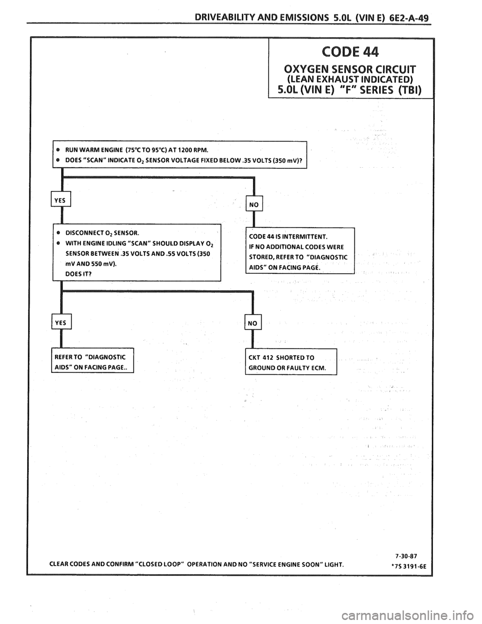
@ WITH ENGINE IDLING "SCAN" SHOULD DISPLAY O2
SENSOR BETWEEN .35 VOLTS AND .55 VOLTS (350