fuel filter location PONTIAC FIERO 1988 Service Repair Manual
[x] Cancel search | Manufacturer: PONTIAC, Model Year: 1988, Model line: FIERO, Model: PONTIAC FIERO 1988Pages: 1825, PDF Size: 99.44 MB
Page 20 of 1825
F CARLINE
ITEM 10
TransmissionRransaxle Service
The manual transmission or transaxle fluid does not
require changing. (Corvette only.) Change fluid in over-
drive unit every 30,000 miles (50 000 km).
For automatic transmissions or transaxles, change
both the fluid and filter every 15,000 miles (25 000 km) if
the car is mainly driven under one or more of these
conditions:
@ In heavy city traffic where the outside temperature
regularly reaches 90°F (32°C) or higher.
@ In hilly or mountainous terrain.
@ Frequent trailer pulling.
@ Uses such as found in taxi, police car or delivery
service.
If you do not use your car under any of these condi-
tions, change both the fluid and filter every 100,000 miles
(160 000 km). See you Owner's Manual for further
details.
ITEM 11
Spark Plug Service*
Replace spark plugs with type listed in your Owner's
Manual.
ITEM 12
Spark Plug Wire Inspection*
Clean wires and inspect for burns, cracks or other dam-
age. Check the wire boot fit at distributor and at spark plugs.
Replace wires as needed.
ITEM 13
Positive Crankcase Ventilation (PCV) Valve
Inspection*
Inspect valve for proper function. Replace valve if
necessary as well as any worn, plugged or collapsed
hoses.
ITEM 14
EGR System Service*
Conduct EGR System Service as referenced in the
EGR System Chart shown in the appropriate 6E Section.
Also, refer to your GM maintenance schedule booklet for
specific applications.
ITEM 15
Air Cleaner and PCV Filter Replacement*
On 1.6 and 2.0 liter engines, replace every 50,000
miles (80 000 km). On all other engines, replace every
30,000 miles (50 000 km). Replace more often under
dusty conditions. Ask your dealer for the proper replace-
ment interval for your driving conditions.
MAINTENANCE AND LUBRICATION 08-3
ITEM 16
Engine Timing Check*
Adjust timing to underhood label specifications. If
no specifications are shown, no adjustment is needed.
ITEM 17
Fuel Tank, Cap and Lines Inspection*
Inspect fuel tank, cap and lines (including fuel rails
and injection assembly, if so equipped) for damage or
leaks. Inspect fuel cap gasket for an even filler neck
imprint or any damage. Replace parts as needed.
ITEM 18
Thermostatically Controlled Air Cleaner
Inspection*
If your car is equipped, inspect all hoses and ducts
for proper hookup. Make sure valve works properly.
OWNER INSPECTIONS AND SERVICES
Listed below are inspections and services which
should be made by either you or a qualified technician at
the intervals shown to help ensure proper safety, emission
performance and dependability of your car. Take any
problems promptly to your dealer or another qualified
technician for service advice. Whenever repairs are neces-
sary, have them completed at once. For your safety and
that of others, any safety-related parts that could have
been damaged in an accident should be inspected and all
needed repairs should be done before operating your car.
Be sure to use the proper fluids and lubricants as shown in
Figure OB-2.
WHILE OPERATING YOUR VEHICLE
Automatic transmissionltransaxle shift indi-
cator operation - Make sure the indicator points to the
gear chosen.
Horn operation - Blow the horn occasionally to
make sure it works. Check all button locations.
I
Brake system operation -- Be alert to abnormal
sounds, increased brake pedal travel or repeated pulling to
one side when braking. Also, if a brake warning light
comes on or flashes, or the anti-lock warning light (if
equipped) comes on or remains on, something may be
wrong with part of the brake system. Have it inspected and
repaired at once.
Exhaust system operation - Be alert to any
changes in the sound of the system or any smell of fumes.
These are signs the system may be leaking or overheating.
.
Have it inspected and repaired at once. Also see "Engine
Exhaust Gas Caution (Carbon Monoxide)" and "Catalytic
Converter" in your Owner's Manual.
*An Emission Control Service
Page 434 of 1825
ENGINE FUEL 6C.3
a Fuel feed and return pipes are secured to the
underbody with clamps and screw assemblies.
The pipes should be inspected occasionally for
leaks, kinks or dents.
e Follow the same routing as the original pipe.
e Pipes must be properly secured to the frame to
prevent chafing. A minimum of 6 mm
(1/4")
clearance must be maintained around a pipe to
prevent contact and chafing.
MPFl Fuel Pipes
Due to the fact that fuel pipes are under high
pressure, these systems require special consideration for service.
Many feed and return pipes use screw couplings
with
"0" Rings. Any time these fittings are loosened
to service or replace components, ensure that:
a A backup wrench is used while loosening and
tightening the fitting.
e Check all "0" rings at fitting locations (if
applicable) for cuts or any damage and replace
any that appear worn or damaged.
e Use correct torque when tightening fittings.
If pipes are replaced always use original
equipment parts, or parts that meet GM
specifications.
Fuel and Vapor Hoses
NOTICE: Fuel and vapor hoses are specially
manufactured. If replacement becomes necessary,
it is important to use only replacement hoses
meeting GM Specification 6163-M. These hoses
are identified with the words "Fluoroelastomer"
on them. Hoses not so marked could cause early
failure, or fail to meet emission standards.
e Do not use rubber hose within 4" of any part of
the exhaust system, or within
10" of the catalytic
converter.
FUEL PUMP
The electric fuel pump is in the fuel tank. The
tank has an outlet for a vapor return system. Any vapor
which forms is returned to the fuel tank along with hot
fuel through a separate line. This greatly reduces any
possibility of vapor lock by keeping cool fuel from the
tank constantly circulating through the fuel pump.
FUEL PUMP RELAY
To control fuel pump operation, a fuel pump
relay is used.
When the ignition switch is turned to "RUN"
position, the fuel pump relay activates the electric fuel
pump for
1.5 to 2.0 seconds to prime the injector(s). If
the ECM does not receive reference pulses from the
distributor after this time, the ECM signals the relay
to turn off the fuel pump. The relay will once again
activate the fuel pump when the
ECM receives
distributor reference pulses.
Fuel Filter
CAUTION: To reduce the risk of fire
and personal injury, it is necessary
to
relieve the fuel system pressure
before servicing fuel system
components. (See Fuel System
Pressure Relief.)
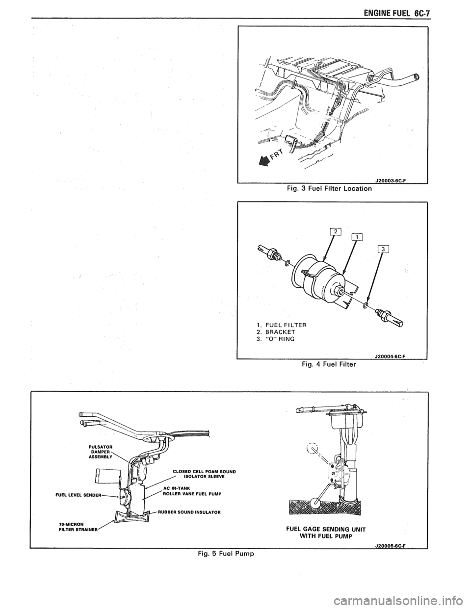
The inline filters can be found on the rear
crossmember of the vehicle. Always use a backup
wrench any time that the fuel filter is removed or
installed. Also make sure that a good
"0" Ring is used
at all screw couple locations. Torque on fittings is
30
N-m (22 lb. ft.).
FUEL TANK
The fuel tank is usually located under the rear of
the vehicle and a number of shapes and sizes are used
depending on the application.
The tank is held in place by two metal straps,
hinged (with a bolt through the hinge) and secured at
the opposite end with a nut and bolt assembly.
Anti-squeak pieces are used on top of the tank to
reduce rattles and other annoying noises.
The fuel tank, cap and lines should be inspected
for road damage, whch could cause leakage. Inspect
fuel cap for correct sealing and indications of physical
damage. Replace any damaged or malfunctioning
parts.
Before attempting service of any type on the fuel
tank, always
(1) remove negative battery cable from
battery, (2) place "no smoking" signs near work areas,
(3) be sure to have C02 fire extinguisher handy, (4)
wear safety glasses and
(5) siphon or pump fuel into an
explosion proof container.
Fuel Filler Gap
The fuel tank filler neck is equipped with a
screw-type cap. The threaded part of the cap requires
several turns counterclockwise to remove. The long
threaded area is designed to allow any remaining fuel
tank pressure to escape while the cap is being removed.
A built-in torque-limiting device prevents
overtightening. To install, turn the cap clockwise until
a clicking noise is heard. This signals that the correct
torque has been reached and the cap is fully seated.
N OTI G E: If a fuel filler cap requires replacement,
use only a cap with the same features. Failure to
use the correct cap can result in a serious
malfunction of the system.
Available on some models is an electric locking
fuel filler cap. Information on this option will be found
in Section
9E.
FUEL TANK FILLER NECK
To help prevent refueling with leaded gasoline,
the fuel filler neck on gasoline engine cars has a built-in
restrictor and deflector. The opening in the restrictor
will only admit the smaller unleaded gas nozzle spout,
which must be fully inserted to bypass the deflector.
Attempted refueling with a leaded gas nozzle or failure
Page 438 of 1825
ENGINE FUEL 6C-7
Fig. 3 Fuel Filter Location
1. FUEL 1 2. BRACKET I
I
3. "0" RING
Fig. 4 Fuel Filter
PULSATOR
LOSE0 CELL FOAM SOUND
ISOLATOR SLEEVE
FUELLEVEL SENDER ROLLER
VANE FUEL PUMP
RUBBER SOUND INSULATOR
FILTER STRAINER FUEL GAGE SENDING UNIT WITH FUEL PUMP
Fig. 5 Fuel Pump
Page 584 of 1825
DRIVEABILITY AND EMISSIONS - 5.OL (VIN El CEZ-C2-9
u PART IDENTIFICATION NUMBER
VENDOR IDENTlFlCATl
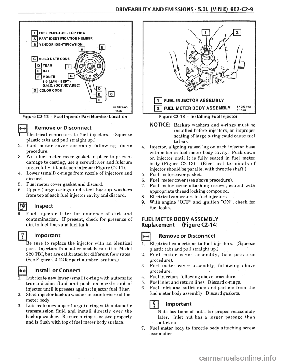
Figure C2-12 - Fuel Injector Part Number Location
Remove or Disconnect
lectrical connectors to fuel injectors. (Squeeze
plastic tabs and pull straight
up.)
2. Fuel meter
cover assembly following above
procedure.
3. With fuel meter cover gasket in place to prevent
damage to casting, use a screwdriver and fulcrum
to carefully lift out each injector (Figure
C2-11).
4. Lower (small) o-rings from nozzle of injectors and
discard.
5. Fuel meter cover gasket and discard.
6. Upper (large o-rings and steel backup washers
from top of each fuel injector cavity and discard.
Inspect
@ Fuel injector filter for evidence of dirt and
contamination.
If present, check for presence of
dirt in fuel lines and fuel tank.
Important
Be sure to replace the injector with an identical
part. Injectors from other models can fit in Model
220 TBI, but are calibrated for different flow rates.
(See Figure
C2-12 for part number location.)
Install or Connect
1. Lubricate new lower (small) o-ring with automatic
transmission fluid and push on nozzle end of
injector until it presses against
in,jector fuel filter.
2. Steel injector backup washer in counterbore of fuel
meter body.
3. Lubricate new upper (large) o-ring with automatic
transmission fluid and install directly over
the
backup washer. Be sure o-ring is seated properly
and is flush with top of fuel meter body surface.
I I 1 I FUEL INJECTOR ASSEMBLY
FUEL METER BODY ASSEMBLY
~p,~9~~~As
Figure C2-13 - Installing Fuel Injector
NOTICE: Backup washers and o-rings must be
installed before injectors, or improper
seating of large o-ring
could cause fuel
to leak.
4. Injector, aligning raised lug on each injector base
with notch in fuel meter body cavity. Push down
on injector until it is fully seated in fuel meter
body (Figure
C2-13). (Electrical terminals of
injector should be parallel with throttle shaft.)
5. Fuel meter cover gasket.
6. Fuel meter cover (see above procedure).
7. Fuel meter cover attaching screws, coated with
appropriate thread locking compound.
8. Electrical connectors to fuel injectors.
9. With engine "OFF" and ignition "ON", check for
fuel leaks.
FUEL METER BODY ASSEMBLY
Replacement (Figure
CZ-14)
a Remove or Disconnect
1. Electrical connections to fuel injectors. (Squeeze
plastic tabs and pull straight up.)
2. Fuel meter cover assembly, (see previous
procedure).
3. Fuel
meter cover assembly, following above
procedure.
4. Fuel injectors, following above procedure.
5. Fuel inlet and return lines. Discard o-rings.
6. Fuel inlet and outlet nuts and gaskets from the
fuel meter body assembly. Discard gaskets.
Important
Note locations of nuts, for proper reassembly
later. Inlet nut has a larger passage than
outlet nut.
7. Fuel meter body to throttle body attaching screw
assemblies.
Page 649 of 1825
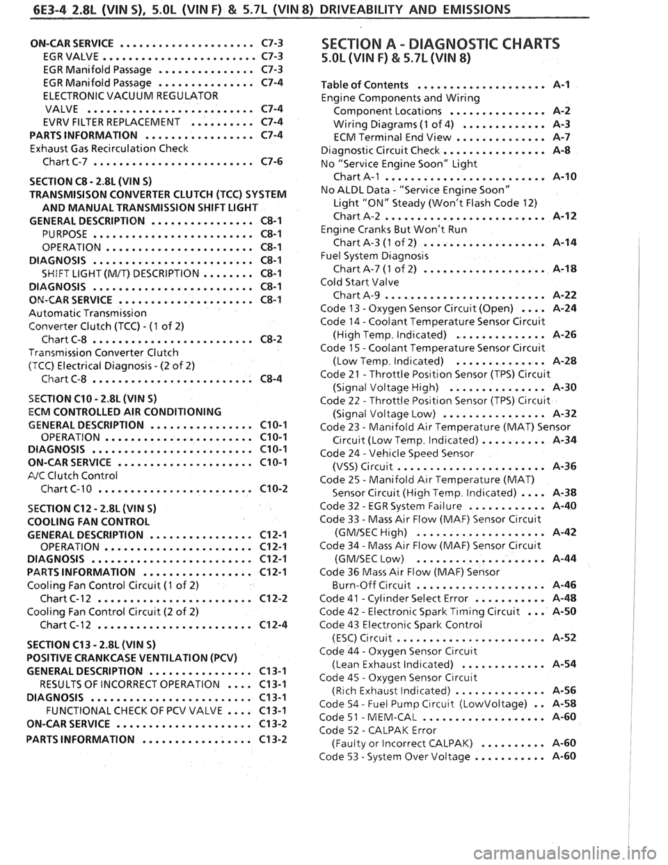
6E3-4 2.8L (VIN S) . 5.OL (VIN F) & 5.7L (VIN 8) DRIVEABILITY AND EMISSIONS
ON-CAR SERVICE ..................... C7-3
EGRVALVE
........................ C7-3
EGR Manifold Passage
............... C7-3
EGR Manifold Passage
............... C7-4
ELECTRONIC VACUUM REGULATOR
VALVE
.......................... C7-4
EVRV FILTER REPLACEMENT
.......... C7-4
PARTS INFORMATION
................. C7-4
Exhaust Gas Recirculation Check
Chart C-7
......................... C7-6
SECTION
C8 . 2.8L (VIN S)
TRANSMISISON CONVERTER CLUTCH (TCC) SYSTEM
AND MANUAL TRANSMISSION SHIFT LIGHT
GENERAL DESCRIPTION
................ C8-1
PURPOSE ......................... C8-1
OPERATION ....................... C8-1
DIAGNOSIS
......................... C8-1
SHIFT LIGHT (M/T) DESCRIPTION ........ C8-1
DIAGNOSIS
......................... C8-1
ON-CAR SERVICE ..................... C8-1
Automatic Transmission
Converter Clutch (TCC)
. (1 of 2)
Chart C-8
......................... C8-2
Transmission Converter Clutch
(TCC) Electrical Diagnosis
. (2 of 2)
Chart C-8
......................... C8-4
SECTION C10 . 2.8L (WIN S)
ECM CONTROLLED AIR CONDITIONING
GENERAL DESCRIPTION
................ C10-1
OPERATION ....................... C10-1
DIAGNOSIS ......................... C10-1
ON-CARSERVICE ..................... C10-1
FJC Clutch Control
Chart C-
1 0 ........................ C10-2
SECTION C12 . 2.8L (VlN S)
COOLING FAN CONTROL
GENERAL DESCRIPTION
................ C12-1
OPERATION ....................... C12-1
DIAGNOSIS
......................... C12-1
PARTS INFORMATION ................. C12-1
Cooling Fan Control Circuit (1 of 2)
Chart
C- 12 ........................ C12-2
Cooling Fan Control Circuit (2 of 2)
Chart C-12
........................ C12-4
SECTION C13
. 2.8L (WIN S)
POSITIVE CRANKCASE VENTILATION (PCV)
GENERAL DESCRIPTION
................ C13-1
RESULTS OF INCORRECT OPERATION
.... C13-1
DIAGNOSIS
......................... C13-1
FUNCTIONALCHECK OF PCV VALVE .... C13-1
ON-CAR SERVICE
..................... C13-2
PARTS INFORMATION
................. C13-2
SEC"T0N A . DIAGNOSTIC CHARTS
5.OL (VIN F) & 5.7L (VIN 8)
.................... Table of Contents A-1
Engine Components and Wiring
............... Component Locations A-2
Wiring Diagrams
(1 of 4) ............. A-3
ECM Terminal End View
.............. A-7
Diagnostic Circuit Check
................ A-8
No "Service Engine Soon" Light
......................... Chart A-1 A-10
No ALDL Data
. "Service Engine Soon"
Light "ON" Steady (Won't Flash Code 12)
Chart A-2
......................... A-12
Eng~ne Cranks But Won't Run
Chart A-3
(1 of 2) ................... A-14
Fuel System
Diagnos~s
Chart A-7 (1 of 2) ................... A-18
Cold Start Valve
Chart A-9
......................... A-22
Code 13
. Oxygen Sensor Circuit (Open) .... A-24
Code 14
. Coolant Temperature Sensor Circuit
(High Temp
. Indicated) .............. A-26
Code
1 5 . Coolant Temperature Sensor C~rcuit
. .............. (Low Temp Ind~cated) A-28
Code 21
. Throttle Pos~tlon Sensor (TPS) Circuit
(Signal Voltage High)
............... A-30
Code 22
. Throttle Pos~t~on Sensor (TPS) Circuit
................ (Signal Voltage Low) A-32
Code 23
. Manifold Air Temperature (MAT) Sensor
C~rcuit (Low Temp . Indicated) .......... A-34
Code 24
. Vehicle Speed Sensor
....................... (VSS) Circuit A-36
Code 25
. Manifold Air Temperature (MAT)
Sensor Circuit (High Temp
. Indicated) .... A-38
. ............ Code 32 EGR System Failure A-40
Code 33
. Mass Air Flow (MAF) Sensor Circuit
.................... (GMISECHlgh) A-42
Code 34
. Mass Air Flow (MAF) Sensor Circu~t
.................... (GMISEC Low) A-44
Code 36 Mass Air Flow
(MAF) Sensor
.. ..... ........... Burn-Off Circuit , , A-46
. ........... Code 41 Cyl~nder Select Error A-48
... . Code 42 Electronic Spark Timing Circuit A-50
Code 43 Electronic Spark Control
(ESC)
C~rcuit ....................... A-52
Code 44
. Oxygen Sensor Circu~t
(Lean Exhaust lnd~cated) ............. A-54
Code 45
. Oxygen Sensor Circuit
(Rich Exhaust Indicated)
.............. A-56
Code 54
. Fuel Pump C~rcuit (Lowvoltage) . . 14-58
. ................... Code 51 MEM-CAL A-60
Code 52
. CALPAK Error
.......... (Faulty or Incorrect CALPAK) A-60
. ........... Code 53 System Over Voltage A-60
Page 984 of 1825
DRIVEABILITY AND EMISSIONS - FUEL INJECTION 6E-23
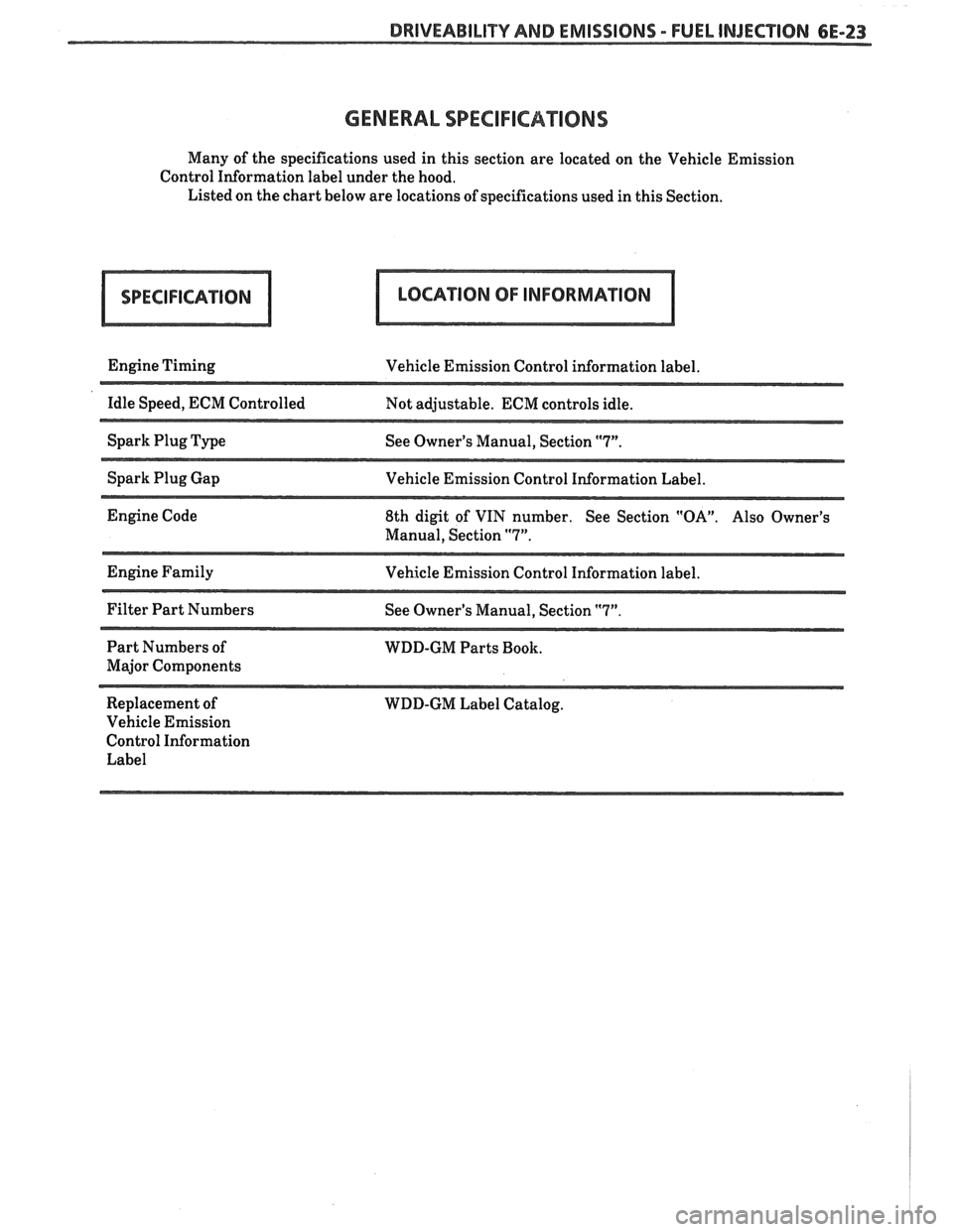
GENERAL SPECIFICA"I0NS
Many of the specifications used in this section are located on the Vehicle Emission
Control Information label under the hood.
Listed on the chart below are locations of specifications used in this Section.
Engine Timing
Vehicle Emission Control information label.
--
Idle Speed, ECM Controlled
Not adjustable. ECM controls idle.
Spark Plug Type
See Owner's Manual, Section
"7".
Spark Plug Gap
Vehicle Emission Control Information Label.
Engine Code
8th digit of VIN number. See Section
"OA". Also Owner's
Manual, Section
"7".
Engine Family
Vehicle Emission Control Information label.
Filter Part Numbers
See Owner's Manual, Section
"7".
Part Numbers of
WDD-GM Parts Book.
Major Components
Replacement of WDD-GM Label Catalog.
Vehicle Emission
Control Information Label