trunk PONTIAC FIERO 1988 Service Repair Manual
[x] Cancel search | Manufacturer: PONTIAC, Model Year: 1988, Model line: FIERO, Model: PONTIAC FIERO 1988Pages: 1825, PDF Size: 99.44 MB
Page 21 of 1825
OB-4 MAINTENANCE AND LUBRICATION
Tire and wheel operation - Be alert to a vibra-
tion of the steering wheel or seat at normal highway
speeds. This may mean a wheel balance is needed. Also, a
pull right or left on a straight, level road may show the
need for
a tire pressure adjustment or wheel alignment.
Steering system operation - Be alert to
changes in steering action. An inspection is needed when
the steering wheel is harder to turn or has too much free
play or if unusual sounds are noted when turning or
parking.
Headlight aim operation - Take note of light
pattern occasionally. If beam aim doesn't look right,
headlights should be adjusted.
AT EACH FUEL FILL
Engine oil level check - Check engine oil level
and add if necessary. See your Owner's
Manual for further
details.
NOTICE: A large loss in this system may indicate a
problem. Have it inspected and repaired at once.
Engine coolant level and condition - Check
engine coolant level in coolant reservoir tank and add if
necessary. Replace if dirty or rusty. See your Owner's
Manual for further details.
NOTICE: A large loss in this system may indicate a
problem. Have it inspected and repaired at once.
Windshield washer fluid level check -- Check
washer fluid level in container and add if necessary.
Hood latch operation - When opening hood on
cars equipped with hoods that open from the front, note
the operation of secondary latch. It should keep hood from
opening all the way when primary latch is released. Make
sure that hood closes firmly.
AT LEAST MONTI-ILY
Tire and wheel inspection and pressure
check--
Check tires for abnormal wear or damage. Also,
check for damaged wheels. Keep pressures as shown on
Tire Placard on the driver's door (include spare unless it is
a stowaway). Pressure should b\: checked when tires are
"cold". See "Tires" in Owner's Manual for further
infomation.
Light operation check - Check operation of
license plate light, side-marker lights, headlights includ-
ing high beams, parking lights, taillights, brake lights.
turn signals, backup lights, instrument panel and interior
lights and hazard warning flashers.
Fluid leak check - After the car has been parked
for a while, inspect the surface beneath the car for water,
oil, fuel or other fluids. Water dripping from the air
conditioning system after use is normal. If you notice fuel
leaks or fumes, the cause should be found and corrected at
once.
AT LEAST TWICE A YEAR (FOR EXAMPLE,
EVERY SPRING AND FALL)
Power steering pump fluid level check --
Check power steering pump fluid level in accordance with
Owner's Manual instructions and keep at proper level.
NOTICE: A large loss in this system may indicate a
problem. Have it inspected and repaired at once.
Brake master cylinder reservoir fluid level
check ---- Check fluid and keep at proper level. Note: It is
normal for the brake fluid level to go down slightly as the
brake pads wear
- so be sure to keep reservoir filled.
NOTICE: A large loss in this system may indicate a
problem. Have
it inspected and repaired at once.
Clutch system service --- manual transmis-
sionltransaxle --- For cars equipped with hydraulic
clutch system, check the reservoir fluid level and add fluid
as required. All others, check clutch pedal free travel and
adjust as necessary. See your Owner's Manual for further
details.
~
NOTICE: A large loss in this system may indicate a
problem. Have it inspected and repaired at once.
Weatherstrip Lubrication - Clean surface and
then apply a thin film of silicone grease with a clean cloth.
EACH TIME OIL IS CHANGED
Automatic and manual transmissionltrans-
axle fluid level check - Check transmission/transaxle
fluid level and add as required. (Corvette only) if equipped
with manual transmission
- check fluid in the overdrive
unit and add as required.
NOTICE: A large loss in this system may indicate a
problem. Have
it inspected and repaired at once.
Brake systems inspection - For convenience,
the following should be done when wheels are removed
for rotation: Inspect lines and hoses for proper hookup,
binding, leaks, cracks, chafing, etc. Inspect disc brake
pads for wear and rotors for surface condition. Also in-
spect drum brake linings for wear and cracks. Inspect
other brake parts, including drums, wheel cylinders, park-
ing brake, etc. at the same time. Check parking brake
adjustment.
INSPECT BRAKES MORE OFTEN IF DRIVING
HABITS OR CONDITIONS RESULT IN FREQUENT
BRAKING.
Steering, suspension and front drive axle
boot and seal inspection
- Inspect front and rear
suspension and steering system for damaged, loose or
missing parts, signs of wear or lack of lubrication. Inspect
power steering lines and hoses for proper hookup, bind-
ing, leaks, cracks, chafing, etc. (On cars equipped with
manual steering gear, check for seal leakage.) On
front-
wheel-drive cars, clean then inspect drive axle boot seals
for damage, tears or leakage. Replace seals if necessary.
Exhaust system inspection - Inspect complete
system. Inspect body near the exhaust system. Look for
broken, damaged, missing or out-of-position parts as well
as open seams, holes, loose connections or other condi-
tions which could cause a heat buildup in the tloor pan or
could let exhaust fumes seep into the trunk or passenger
compartment.
Page 117 of 1825

2C-10 CHASSIS SHEET METAL
ROCKER PANEL AIR DEFLECTOR
Remove or Disconnect
1. Five top screws (#I).
2. Hoist car.
3. Seven bolts holding rocker panel rubber
air
deflector
(#2) and remove.
4. Seven screws holding rocker deflector to bottom
of rocker panel
(#3).
5. Two screws holding rear rocker deflector to rear
wheel opening
(#4).
6. Five
push type fasteners at the lower rear of the
wheel well splash shield, lift shield to gain
access to the two forward nuts.
7. Two nuts (#5) from rocker deflector front to
fender.
8. Rocker deflector.
9. Nine screws holding rocker panel deflector
support.
10. Support.
Install or Connect
To install, reverse removal procedure.
REAR BUMPER FASCIA EXTENSION
Remove or Disconnect
1. Hoist car,
2. Drill out
eight fascia extension to fascia rivets
(#I) (four each side). Four
bolts from fascia extension to lower quar-
ter panel
(#2).
Five (each side) push clips from fascia to sup-
port
(443).
Four screws from rear fascia extension to fender
(#4).
Lower car.
Right side trunk trim and spare tire.
Rear trim panel.
Left trim panel.
Right and left side fascia and fascia extension
nuts (six each side)
(#5).
Right and left tail lamp wing nuts and remove
housing.
Seven fascia push nuts and disconnect electrical
connector for license plate
(#6).
Rear bumper fascia from car.
Twelve (six each side) fascia extension to fascia
retaining nuts and remove fascia extension
(#7).
Install or Connect
To install, reverse removal procedure.
Page 986 of 1825
EXHAUST SYSTEM 6F-1
SEC"B0N 6F
EXHAUST SYSTEM
CAUTION: Exhaust system components should avoid overheating and possible damage to the
have enough clearance from the underbody to passenger compartment carpets.
................................. General Description 6F- 1 Hanger ............................................................ 6F- I
..................... ....................... Exhaust Pipe .. 6F- I Clamp ............................................................ 6F- I
Muffler .......................................................... 6F- 1 Catalytic Converter ......................................... 6F- 1
.......................... Resonator ........................... .. 6F- 1
GENERAL DESGRIP"F0N
When inspecting or replacing exhaust system
components, make sure there is adequate clearance
from all points on the underbody to avoid possible
overheating of the floor pan and possible damage to the
passenger compartment insulation and trim materials.
Check complete exhaust system and nearby body
areas and trunk lid for broken, damaged, missing or
mispositioned parts, open seams, holes, loose
connections or other deterioration which could permit
exhaust fumes to seep into the trunk or passenger
compartment. Dust or water in the trunk may be an
indication of a problem in one of these areas. Any
defects should be corrected immediately. To help
insure continued integrity, the exhaust system pipe
qever a
rearward of the muffler must be replaced whe.-
new muffler is installed.
EXHAUST PlPE
The exhaust manifold to crossover pipe
connections are of the ball type, thus eliminating the
need for gaskets.
MUFFLER
The mufflers are a tri-flow design. Some muffler
installations have a slot in the inlet and/or outlet pipe
which indexes to a key (tab) welded on the exhaust
and/or tail pipe to help maintain alignment.
RESONATOR
A resonator is used on some series exhaust
systems. It allows the use of mufflers with less back
pressure and provides for optimum tuning
characteristics of the exhaust system. The
installation of exhaust system supports is
very important as improperly installed supports can
cause annoying vibrations which are difficult to
diagnose.
CLAMP
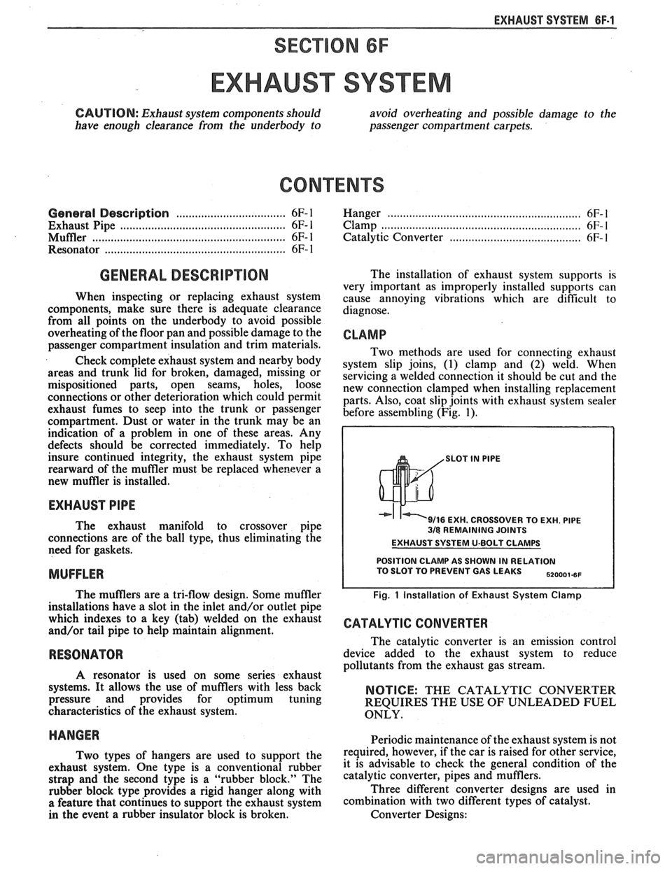
Two methods are used for connecting exhaust
system slip joins, (1) clamp and
(2) weld. When
servicing a welded connection it should be cut and the
new connection clamped when installing replacement
parts. Also, coat slip joints with exhaust system sealer
before assembling (Fig. 1).
SLOT IN PlPE
9/16 EXH. CROSSOVER TO EXH. PlPE 318 REMAINING JOINTS
EXHAUST SYSTEM U-BOLT CLAMPS
POSITION CLAMP AS SHOWN IN RELATION TO SLOT TO PREVENT GAS LEAKS ,,ooo,.,,
Fig. 1 Installation of Exhaust System Clamp
CATALYTIC CONVERTER
The catalytic converter is an emission control
device added to the exhaust system to reduce
pollutants from the exhaust gas stream.
NOTICE: THE CATALYTIC CONVERTER
REQUIRES THE USE OF UNLEADED FUEL
ONLY.
HANGER Periodic maintenance of the exhaust system is not
T~~ types of hangers are used to support the required, however, if the car is raised for other service,
exhaust system. one type is a conventional rubber it is advisable to check the general condition of the
strap and the second type is a "rubber block." The catalytic converter, pipes and mufflers.
rubber block type provides a rigid hanger along with Three
different converter designs are used in
a feature that continues to support the exhaust system combination with two different types of catalyst.
in the event a rubber insulator block is broken. Converter Designs:
Page 1434 of 1825
DRIVER INFORMATION CENTER (DIC)
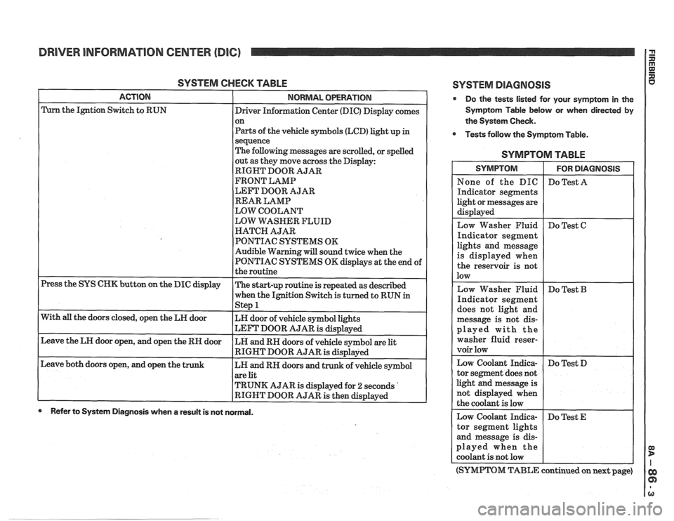
SYSTEM CHECK TABLE
ACTION NORMAL OPERATION
Press the SYS CHK button on the DIC display
With
all the doors closed, open the LH door
Leave the LH door open, and open the RH door
Leave both doors open, and open the
t
Driver Information Center (DIC) Display comes
on
Parts of the vehicle symbols (LCD) light up
in
sequence
The following messages are scrolled, or spelled
out as they move across the Display:
RIGHT DOOR AJAR
FRONT LAMP
LEFT DOOR AJAR
REAR LAMP
LOW COOLANT
LOW WASHER FLUID
HATCH AJAR
PONTIAC SYSTEMS OK
Audible Warning will sound twice when the
PONTIAC SYSTEMS OK displays at the end of
the routine
The start-up routine is repeated as described
when the Ignition Switch is turned to RUN
in - Step 1
LH door of vehicle symbol lights
LEFT DOOR AJAR
is displayed
LH and RH doors of vehicle symbol are
lit
RIGHT DOOR AJAR is displayed
LH and RH doors and trunk of vehicle symbol
are lit
TRUNK AJAR is displayed for
2 seconds '
RIGHT DOOR AJAR is then displayed
0 Refer to System Diagnosis when a result is not normal.
SYSTEM DlAGNOSlS
Do the tests listed for your symptom in the
Symptom Table below or when directed by
the System Check.
Tests follow the Symptom Table.
SYMPTOM TABLE
ights and message
s displayed when
he reservoir is not
ed with the
er fluid
reser-
(SYMPTOM TABLE continued on next page)
Page 1436 of 1825
DRIVER INFORMATION CENTER (DIC)
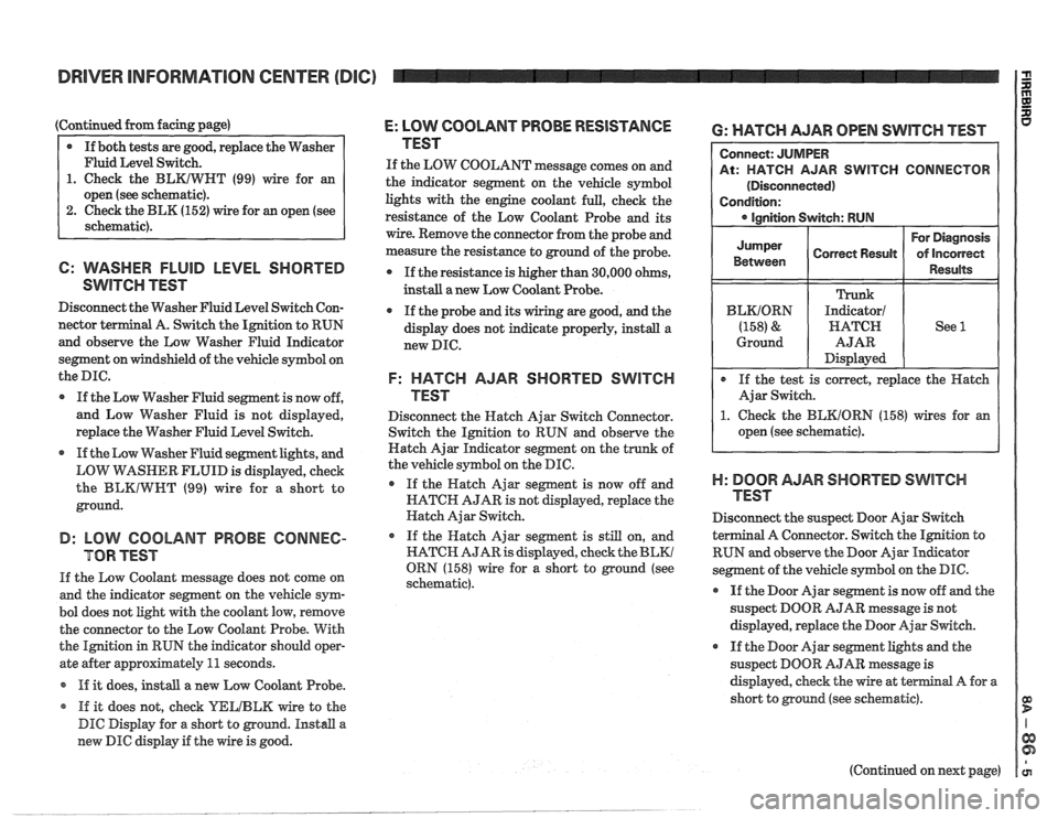
(Continued from facing page)
@ If both tests are good, replace the Washer
Fluid Level Switch.
1. Check the BLKIWHT (99) wire for an
open (see schematic).
2. Check the BLK (152) wire for an open (see
schematic).
6: WASHER FLUID LEVEL SHORTED
SwlTen TEST
Disconnect the Washer Fluid Level Switch Con-
nector
terminal A. Switch the Ignition to RUN
and observe the Low Washer Fluid Indicator
segment on windshield of the vehicle symbol on
the
me.
If the Low Washer Fluid segment is now off,
and Low Washer Fluid is not displayed,
replace the Washer Fluid Level Switch.
If the Low Washer Fluid segment lights, and
LOW
VirASHER FLUID is displayed, check
the
BLKIWWT (99) wire for a short to
ground.
B: LOW COOLANT PROBE CONNEC-
TOR TEST
If the Low Coolant message does not come on
and the indicator segment on the vehicle sym-
bol does not light with the coolant low, remove
the connector to the Low Coolant Probe. With
the Ignition in RUN the indicator
should oper-
ate after approximately
11 seconds.
If it does,
install a new Low Coolant Probe.
* If it does not, check YELIBLM wire to the
DIC Display for a short to ground. Install a
new DIC display if the wire is good.
E: LOW COOLANT PROBE RESISTANCE
TEST
If the LOW COOLANT message comes on and
the indicator segment on the vehicle symbol
lights with the engine coolant full, check the
resistance of the Low Coolant Probe and its
wire. Remove the connector from the probe and
measure the resistance to ground of the probe.
If the resistance is higher than 30,000 ohms,
instdl a new Low Coolant Probe.
If the probe
and its wiring are good, and the
display does not indicate properly, install a
new DIC.
F: HATCH AJAR SHORTED SWITCH
TEST
Disconnect the Hatch Ajar Switch Connector.
Switch the Ignition to RUN and observe the
Hatch Ajar Indicator segment on the trunk of
the vehicle symbol on the DIC.
If the Hatch Ajar segment is now off and
HATCH AJAR is not displayed, replace the
Hatch Ajar Switch.
o If the Hatch Ajar segment is still on, and
HATCH AJAR is displayed, check the
BLKl
ORN (158) wire for a short to ground (see
schematic).
6: WATCH AJAR OPEN SWITCH TEST
R SWITCH CONNECTOR
1. Check the BEKIORN (158) wires for an
open (see schematic).
)-I: BOOR AJAR SHORTED SWITCH
TEST
Disconnect the suspect Door Ajar Switch
a1 A Connector. Switch the Ignition to
RUN and observe the Door Ajar
Indieator
segment of the vehicle symbol on the DIC.
@ If the Door Ajar segment is now off and the
suspect DOOR AJAR message is not
displayed, replace the Door Ajar Switch.
If the Door Ajar segment lights and the
suspect DOOR
AJAR message is
displayed, check the wire at
terminal A for a
short to ground (see schematic).
(Continued on next page)
Page 1437 of 1825
DRIVER INFORMATION CENTER (DIC) I $
(Continued from previous page)
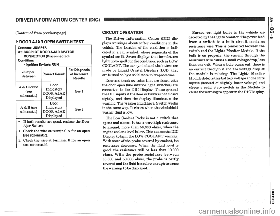
I: DOOR AJAR OPEN SWITCH TEST
At: SUSPECT DOOR AJAR SWITCH
CONNECTOR (Disconnected)
(see schematic).
2. Check the wire at terminal B for an open
(see schematic).
CIRCUIT OPERATION
The Driver Information Center (DIC) dis-
plays warnings about
saftey conditions in the
vehicle. The location of the condition is indi-
cated in a car symbol, where segments of the
symbol are
lit. Seven displays that form letters
light up to spell out the condition, such as LOW
COOLANT. The car symbol and the letters are
made by Liquid
Crystal Displays (LCD) that
are turned on by a solid state microprocessor.
Door and trunk switches that are closed with
the door open (like interior light switches) are
connected to the DIC Display. These ground
the DIC inputs if the door or trunk is not closed
tightly, and then the display illuminates the
warning. The Washer Fluid Level Switch works
in the same way.
It closes when the windshield
washer fluid is low.
The Low Coolant Probe is not a switch that
opens and closes.
It has a very high resistance
to ground, more than 50,000 ohms, when the
engine coolant level is low. This causes the DIC
Display to light the LOW COOLANT w
With more of the probe covered by coolant, its
resistance decreases. When the fluid level is
good, the resistance
will be less than 10,000
ohms. With the probe resistance between
10,000 and 50,000 ohms, the probe is partly
covered and the fluid is not low enough to cause
the warning to be displayed. Burned
out light bulbs in the vehicle are
detected by the Lights Monitor. The power feed
from a switch to a bulb circuit contains
resistance wire. This is connected between the
switch and the Lights Monitor Module.
If the
bulb is on properly, the current through the
resistance wire causes a small voltage drop, less
than one volt. When a bulb burns out, there is
no current through it
and the voltage drop at
the module is missing. The Lights Monitor
Module detects this battery voltage at one of its
inputs (instead of slightly lower voltage) and
closes a solid state switch in the Module to
g to appear in the DIC Display.
Page 1766 of 1825
ROOF - F STYLE 8H-7
SECTION A-A VIEW A
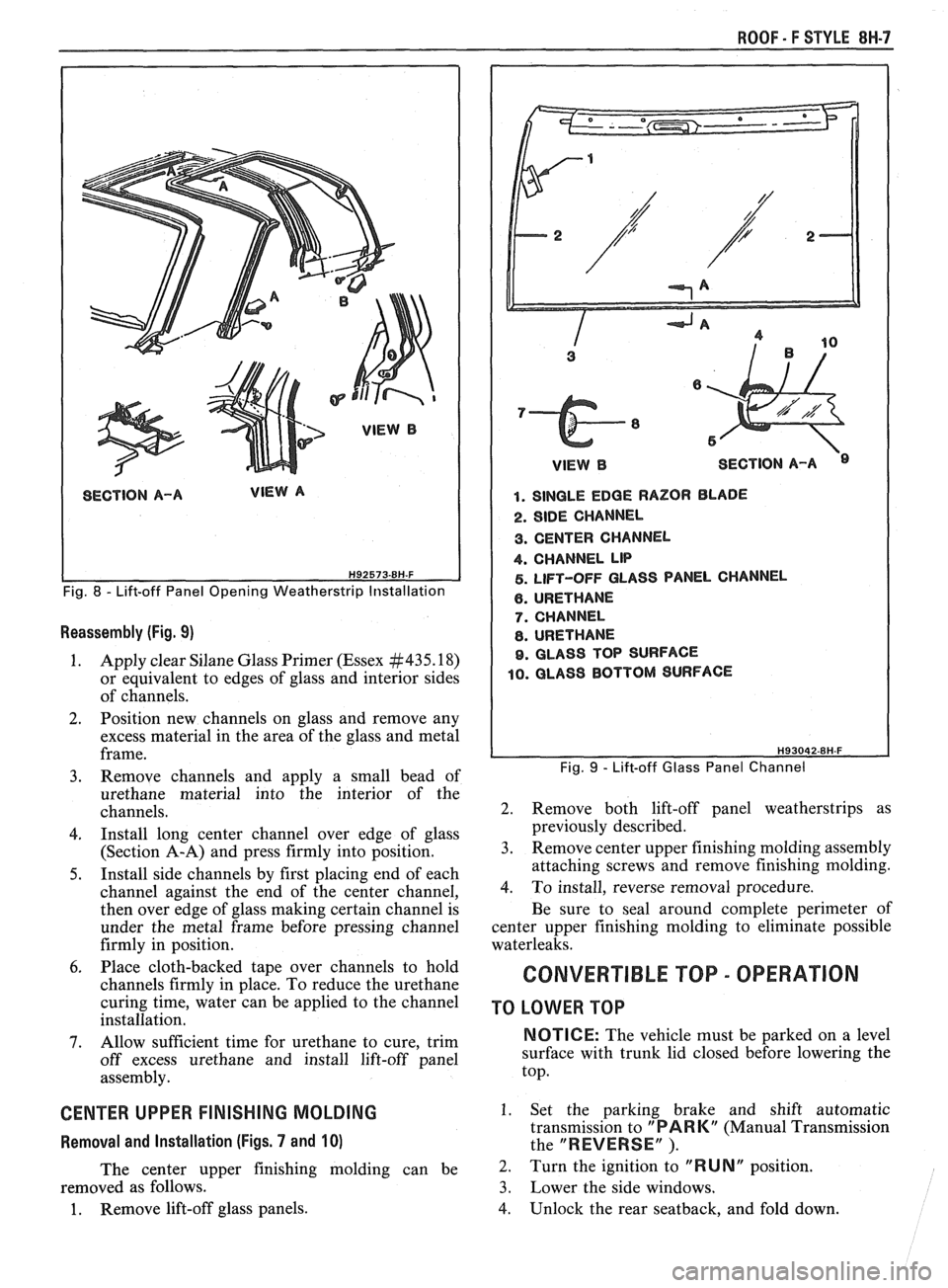
Fig. 8 - Lift-off Panel Opening Weatherstrip Installation
Reassembly (Fig. 9)
1. Apply clear Silane Glass Primer (Essex #435.18)
or equivalent to edges of glass and interior sides
of channels.
2. Position new channels on glass and remove any
excess material in the area of the glass and metal
frame.
3. Remove channels and apply a small bead of
urethane material into the interior of the
channels.
4. Install long center channel over edge of glass
(Section A-A) and press firmly into position.
5. Install side channels by first placing end of each
channel against the end of the center channel,
then over edge of glass making certain channel is
under the metal frame before pressing channel
firmly in position.
6. Place cloth-backed tape over channels to hold
channels firmly in place. To reduce the urethane
curing time, water can be applied to the channel
installation.
7. Allow sufficient time for urethane to cure, trim
off excess urethane and install lift-off panel
assembly.
CENTER UPPER FINISHING MOLDING
Removal and Installation (Figs. 7 and 10)
The center upper finishing molding can be
removed as follows.
1. Remove lift-off glass panels.
1 VlEWB SECTION A-A
1. SINGLE EDGE RAZOR BLADE
2. SIDE CHANNEL
3. CENTER CHANNEL
4. CHANNEL LIP
5. LIFT-OFF GLASS PANEL CHANNEL
6. URETHANE
7. CHANNEL
8. URETHANE
9. GLASS TOP SURFACE
10. GLASS BOTTOM SURFACE
Fig. 9 - Lift-off Glass Panel Channel
2. Remove both lift-off panel weatherstrips as
previously described.
3. Remove center upper finishing molding assembly
attaching screws and remove finishing molding.
4. To install, reverse removal procedure.
Be sure to seal around complete perimeter of
center upper finishing molding to eliminate possible
waterleaks.
CONVERTIBLE TOP - OPERATION
TO LOWER TOP
NOTICE: The vehicle must be parked on a level
surface with trunk lid closed before lowering the
top.
1. Set the parking brake and shift automatic
transmission to
"PARK" (Manual Transmission
the
"REVERSE" ).
2. Turn the ignition to "RUNN position.
3. Lower the side windows.
4. Unlock the rear seatback, and fold down.
Page 1767 of 1825
8H.8 ROOF - F STYLE
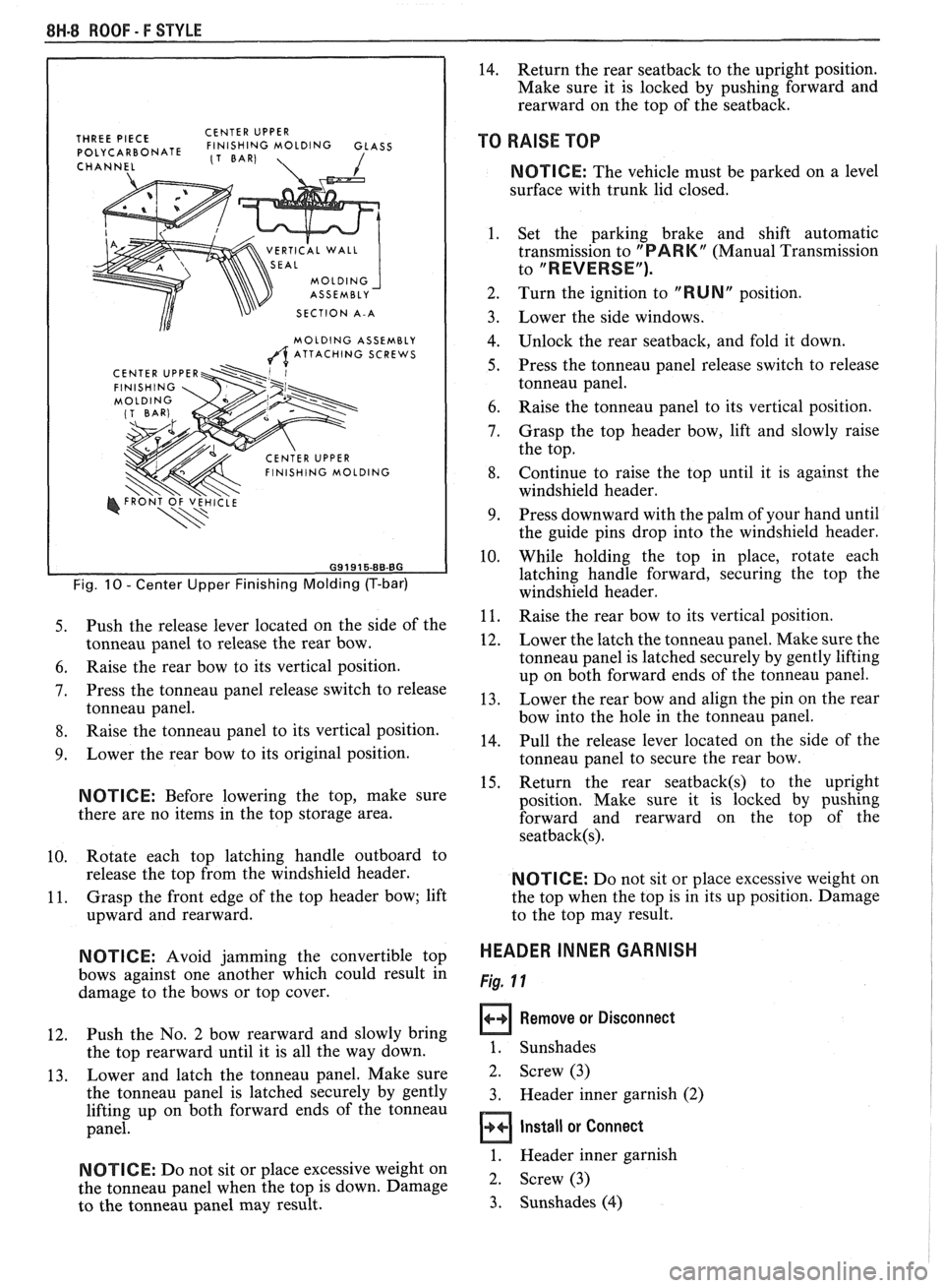
THREE PIECE CENTER
UPPER POLYCARBONATE FINISHING MOLDING GLASS (1 BAR)
CHANNEL 1
VERTICAL WALL
SECTION A-A
MOLDING ASSEMBLY
A ATTACHING SCREWS
Fig. 10 - Center Upper Finishing Molding (T-bar)
5. Push the release lever located on the side of the
tonneau panel to release the rear bow.
6. Raise the rear bow to its vertical position.
7. Press the tonneau panel release switch to release
tonneau panel.
8. Raise the tonneau panel to its vertical position.
9. Lower the rear bow to its original position.
NOTICE: Before lowering the top, make sure
there are no items in the top storage area.
10. Rotate
each top latching handle outboard to
release the top from the windshield header.
11. Grasp
the front edge of the top header bow; lift
upward and rearward.
N OTI C E: Avoid jamming the convertible top
bows against one another which could result in
damage to the bows or top cover.
12. Push the
No. 2 bow rearward and slowly bring
the top rearward until it is all the way down.
13. Lower
and latch the tonneau panel. Make sure
the tonneau panel is latched securely by gently
lifting up on both forward ends of the tonneau
panel.
NOTICE: Do not sit or place excessive weight on
the tonneau panel when the top is down. Damage
to the tonneau panel may result.
14. Return the rear seatback to the upright position.
Make sure it is locked by pushing forward and
rearward on the top of the seatback.
TO RAISE TOP
NOTICE: The vehicle must be parked on a level
surface with trunk lid closed.
1. Set the parking brake and shift automatic
transmission to
"PARK" (Manual Transmission
to
"REVERSE").
2. Turn the ignition to "RUN" position.
Lower the side windows.
Unlock the rear seatback, and fold it down.
Press the tonneau panel release switch to release
tonneau panel.
Raise the tonneau panel to its vertical position.
Grasp the top header bow, lift and slowly raise
the top.
Continue to raise the top until it is against the
windshield header.
Press downward with the palm of your hand until
the guide pins drop into the windshield header.
While holding the top in place, rotate each
latching handle forward, securing the top the
windshield header.
Raise the rear bow to its vertical position.
Lower the latch the tonneau panel. Make sure the
tonneau panel is latched securely by gently lifting
up on both forward ends of the tonneau panel.
Lower the rear bow and align the pin on the rear
bow into the hole in the tonneau panel.
Pull the release lever located on the side of the
tonneau panel to secure the rear bow.
Return the rear
seatback(s) to the upright
position. Make sure it is locked by pushing
forward and rearward on the top of the
seatback(s).
NOTICE: Do not sit or place excessive weight on
the top when the top is in its up position. Damage
to the top may result.
HEADER INNER GARNISH
Fig. 11
Remove or Disconnect
1. Sunshades
2. Screw (3)
3. Header inner garnish (2)
Install or Connect
1. Header inner garnish
2. Screw (3)
3. Sunshades
(4)