climate control PONTIAC GRAND AM 2003 Owners Manual
[x] Cancel search | Manufacturer: PONTIAC, Model Year: 2003, Model line: GRAND AM, Model: PONTIAC GRAND AM 2003Pages: 354, PDF Size: 16.3 MB
Page 2 of 354
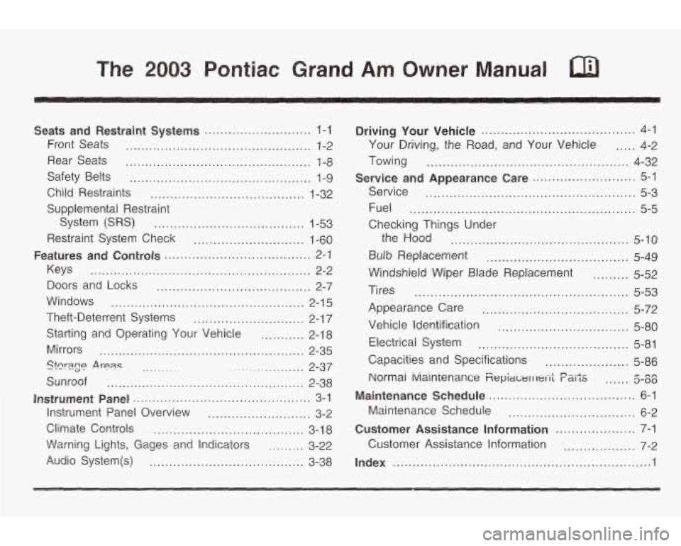
The 2003 Pontiac Grand Am Owner Manual
Seats and Restraint Systems ........................... 1-1
Front Seats ............................................... 1-2
Rear Seats ............................................... 1-8
Safety Belts .............................................. 1-9
Child Restraints ....................................... 1-32
Supplemental Restraint
System
(SRS) ...................................... 1-53
Restraint System Check ............................ 1-60
Keys ........................................................ 2-2
Doors and Locks ....................................... 2-7
Theft-Deterrent Systems ............................ 2-1 7
Starting and Operating Your Vehicle ........... 2-18
Mirrors .................................................... 2-35
Sunroof .................................................. 2-38
Instrument Panel Overview .......................... 3-2
Climate Controls ...................................... 3-1 8
\Warning Lights, Gages a.nd Indicators ......... 3-22
Audio System@) ....................................... 3-38
Features and Controls ..................................... 2-1
Windows ................................................. 2-1 5
Stcr3.g~ .A rean ~ ................... 2-37 ..........
Instrument Panel ............................................. 3-1
Driving Your Vehicle ....................................... 4-1
Your Driving, the Road, and Your Vehicle ..... 4-2
Towing ................................................... 4-32
Service ..................................................... 5-3
Fuel ......................................................... 5-5
Checking Things Under
Service
and Appearance
Care .......................... 5-1
the Hood ............................................. 5-10
Bulb Replacement .................................... 5-49
Windshield Wiper Blade Replacement ......... 5-52
Tires ...................................................... 5-53
Appearance Care ..................................... 5-72
Vehicle Identification ................................. 5-80
Electrical System ...................................... 5-81
Capacities and Specifications ..................... 5-86
Normai iviainienance Fiepiawl I 1t.1-1; F&iJiS ...... 5-00 nn
Maintenance Schedule ..................................... 6-1
bhintenance Schedule ................................ 6-2
Customer Assistance Information .................... 7-1
Customer Assistance Information .................. 7-2
Index ............................................................... ..I
Page 5 of 354
Vehicle Damage Warnings
Also, in this book you will find these notices:
Notice: These mean there is something that could
damage your vehicle.
A notice will tell you about something that can damage
your vehicle. Many times, this damage would not be
covered by your warranty, and it could be costly. But the
notice will
tell you what to do to help avoid the
damage.
When you read other manuals, you might see
CAUTION and NOTICE warnings in different colors
or in different words.
You’ll also see warning labels on your vehicle. They use
the same words, CAUTION or
NOTICE.
Vehicle Symbols
Your vehicle may be equipped with components and
labels that use symbols instead of text. Symbols, used
on your vehicle, are shown along with the text
describing the operation or information relating
to a
specific component, control, message, gage or indicator.
If you need help figuring out a specific name of a
component, gage or indicator reference the following
topics in the Index:
0 “Engine Compartment Overview”
* “Instrument Panei Overview”
0 “Climate Controls’’
“Audio Systems”
Also see
Warning Lights, Gages and Indicators on
page
3-22.
iv
Page 81 of 354

Trunk
To unlock the trunk from the outside, insert the key and
turn the trunk lock cylinder or use the remote keyless
entry transmitter,
if your vehicle has this feature.
When closing the trunk, close from the center
to ensure
it fully latches.
It can be dangerous to drive with the trunk lid
open because carbon monoxide
(CO) gas can
come into your vehicle. You can’t
see or smell
CO. It can cause unconsciousness and even
death.
If you must drive with the trunk lid open
or if electrical wiring or other cable
connections must pass through the seal
between the body and the trunk lid:
Make sure all other windows are shut.
Turn the fan on your heating or cooling
system to its highest speed and select the control setting that will force outside air
into your vehicle. See “Climate Controls”
in the Index.
instrument panel, open them all the way.
If you have air outlets on or under the
See “Engine Exhaust” in the Index.
2-1 2
Page 103 of 354
Running Your Engine While You
Are Parked
It’s better not to park with the engine running. But if you
ever have
to, here are some things to know.
Idling the engine with
the climate control
system
off could allow dangerous exhaust into
your vehicle. See the earlier Caution under
“Engine Exhaust.”
Also, idling in a closed-in place can let deadly carbon monoxide
(CO) into your vehicle even if
the fan is at the highest setting. One place this
can happen is a garage. Exhaust
- with
CO - can come in easily. NEVER park in a
garage with the engine running.
Another closed-in place can be a blizzard. See
“Winter Driving” in the Index.
It can be dangerous to get out of your vehicle
if the shift lever is not fully
in PARK (P) with
the parking brake firmly set. Your vehicle can
roll. Don’t leave your vehicle when the engine
is running unless you have to. If you’ve
left the
engine running, the vehicle can move suddenly. You or others could be injured.
To
be sure your vehicle won’t move, even when
you’re on fairly level ground, always set your
parking brake and move the shift lever to
PARK
(P).
Follow the proper steps to be sure your vehicle won’t
move. See
Shifting Into Park (P) on page 2-30.
If you are parking on a hill and if you’re pulling a trailer,
also see
Towing a Trailer on page 4-37.
2-34
Page 108 of 354
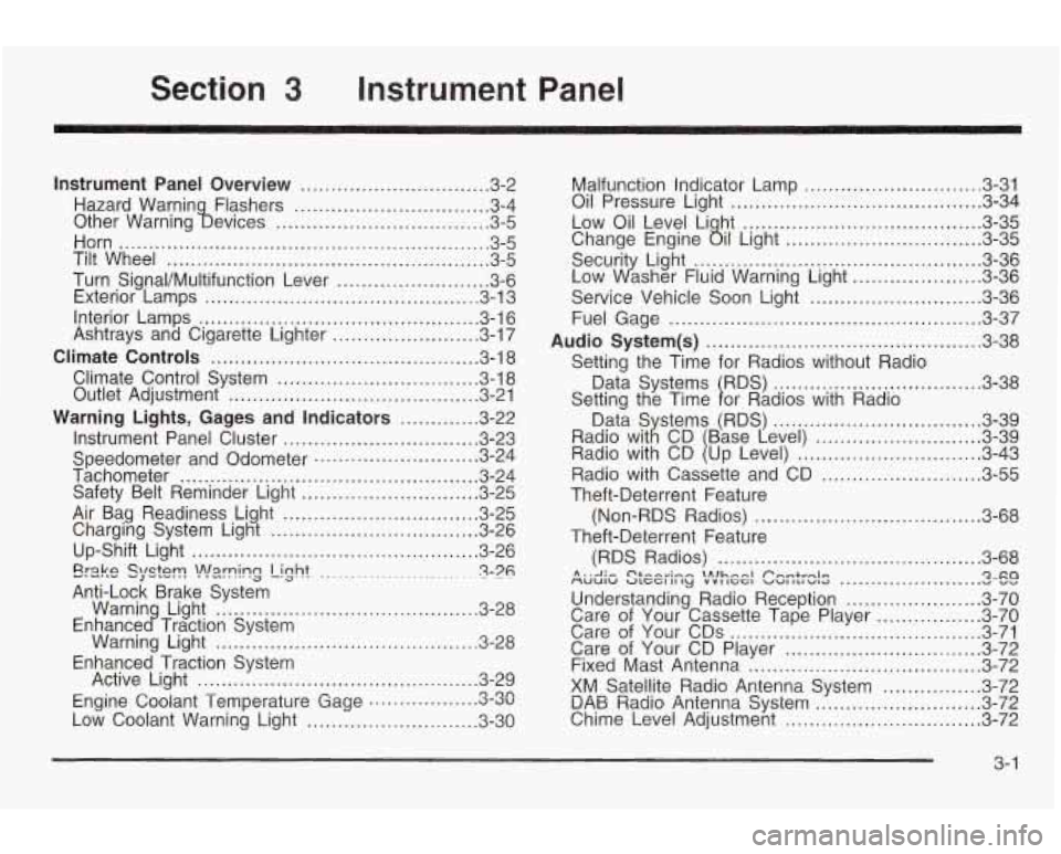
Section 3 Instrument Panel
Instrument Panel Overview ............................... 3.2
Hazard Warnin Flashers
................................ 3.4
Other Warning !bevices
................................... 3.5
Horn
............................................................. 3.5
Tilt Wheel
..................................................... 3.5
Turn Signal/Multifunction Lever
......................... 3.6
Exterior Lamps
............................................. 3.13
Interior Lamps
.............................................. 3.16
Ashtrays and Cigarette Lighter
........................ 3.17
Climate Controls
............................................ 3.18
Climate Control System
................................. 3.18
Outlet Adjustment
......................................... 3.21
Warning Lights, Gages and Indicators
............. 3-22
Instrument Panel Cluster
................................ 3.23
Speedometer and Odometer
........................... 3.24
Tachometer
................................................. 3.24
Safety Belt Reminder Light
............................. 3.25
Air Bag Readiness Light ................................ 3.25
Charging System Light
.................................. 3.26
Up-Shift Light
............................................... 3.26
Erake QlQtT! -J -.-. !n!=lrning Light ........................ ~ 3-76 .
Warnin Light ........................................... 3-28
Warning Light
........................................... 3.28
Active Light
.............................................. 3.29
Low Coolant Warning Light
............................ 3.30
Anti-Lock
Brake System
Enhance
c? Traction System
Enhanced Traction System
Engine Coolant Temperature Gage
3.3~ rl on ..................
Malfunction Indicator Lamp ............................. 3.31
Oil Pressure Light
......................................... 3.34
Low Oil Level Li ht
....................................... 3.35
Securit Light:
............................................... 3-36
Service Vehicle Soon Light
............................ 3-36
Fuel Gage
................................................... 3-37
Audio System(s)
............................................. 3-38
Data Systems RDS)
.................................. 3-38
Change Engine
ail Light ................................ 3-35
Low dsher Fluid Warning Light
..................... 3-36
Setting the Time for Radios without Radio
Setting the Time
1 or Radios with Radio 3-39
........................... 3-39
.............................. 3-43
Radio with Cassette and CD
.......................... 3-55
Theft-Deterrent Feature
Theft-Deterrent Feature (Non-RDS Radios)
..................................... 3-68
(RDS Radios)
........................................... 3-68
MUUIW ULCCI II ly VVI IGGI VU1 ILI WIG v vv A . .A .- C'&-A~;~~ \Alhnnl Pnmtrnlrr Qxa .......................
Understanding Radio Reception ...................... 3-70
Care of Your Cassette Tape Player
................. 3-70
Care of Your CDs ......................................... 3-71
Care of Your CD Player
................................ 3-72
Fixed Mast Antenna ...................................... 3-72
XM Satellite Radio Antenna System
................ 3-72
DAB Radio Antenna System 3-11 Chime Level Adjustment ................................ 3-72
n Tn ...........................
3- 1
Page 110 of 354
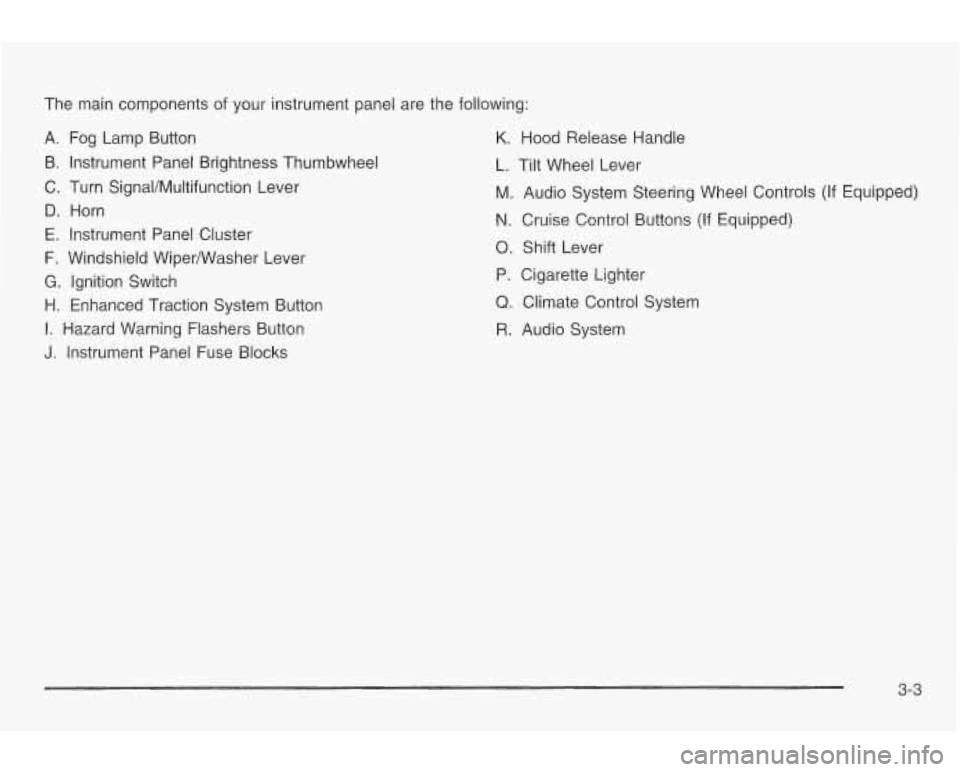
The main components of your instrument panel are the following:
A. Fog Lamp Button
B. Instrument Panel Brightness Thumbwheel
C. Turn SignaVMultifunction Lever
D. Horn
E. Instrument Panel Cluster
F. Windshield WiperNVasher Lever
G. Ignition Switch
H. Enhanced Traction System Button
I. Hazard Warning Flashers Button
J. Instrument Panel Fuse Blocks
K. Hood Release Handle
L. Tilt Wheel Lever
M. Audio System Steering Wheel Controls (If Equipped)
N. Cruise Control Buttons (If Equipped)
0. Shift Lever
P. Cigarette Lighter
Q. Climate Control System
R. Audio System
3-3
Page 125 of 354
Climate Controls
Climate Control System
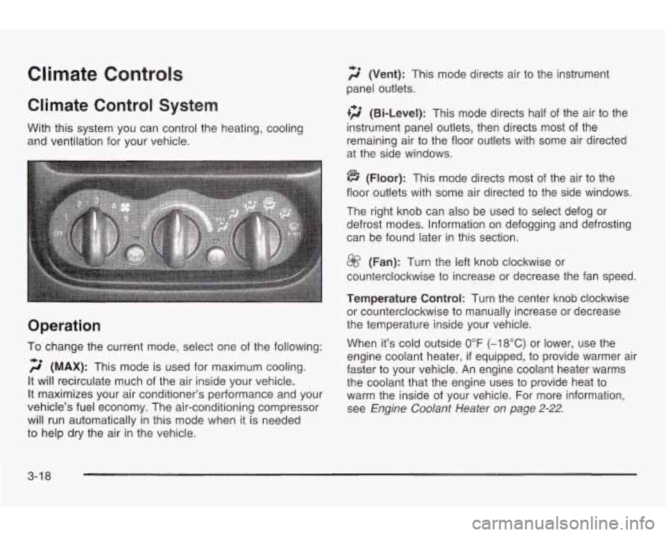
With this system you can control the heating, cooling
and ventilation for your vehicle.
Operation
To change the current mode, select one of the following:
f;’ (MAX): This mode is used for maximum cooling.
It will recirculate much of the air inside your vehicle.
It maximizes your air conditioner’s performance and your
vehicle’s fuel economy. The air-conditioning compressor
will run automatically in this mode when it is needed
to help dry the air in the vehicle.
2 (Vent): This mode directs air to the instrument
panel outlets.
tf;’ (Bi-Level): This mode directs half of the air to the
instrument panel outlets, then directs most of the
remaining air
to the floor outlets with some air directed
at the side windows.
@ (Floor): This mode directs most of the air to the
floor outlets with some air directed to the side windows.
The right knob can
also be used to select defog or
defrost modes. Information on defogging
and defrosting
can be found later in this section.
@ (Fan): Turn the left knob clockwise or
counterclockwise
to increase or decrease the fan speed.
Temperature Control: Turn the center knob clockwise
or counterclockwise to manually increase or decrease
the temperature inside your vehicle.
When it’s cold outside
0°F (-18°C) or lower, use the
engine coolant heater,
if equipped, to provide warmer air
faster to your vehicle. An engine coolant heater warms
the coolant that the engine uses
to provide heat to
warm the inside of your vehicle. For more information,
see Engine
Coolant Heater on page 2-22.
3-1 8
Page 281 of 354
Treadwear Temperature - A, B, C
The
treadwear grade is a comparative rating based on
the wear rate of the tire when tested under controlled
conditions on a specified government test course.
For example, a tire graded
150 would wear one and
a half
(1.5) times as well on the government course as
a tire graded 100. The relative performance of tires
depends upon the actual conditions of their use,
however, and may depart significantly from the norm
due
to variations in driving habits, service practices and
differences in road characteristics and climate.
Traction - AA, A, B, C
The traction grades, from highest to lowest, are AA, A,
B, and C. Those grades represent the tire’s ability
to stop on wet pavement as measured under controlled
conditions on specified government test surfaces of
asphalt and concrete.
A tire marked C may have poor
traction performance. Warning: The traction grade
assigned to this tire is based on straight-ahead braking
traction tests, and does not include acceleration,
cornering, hydroplaning, or peak traction characteristics. The
temperature grades are
A (the highest), B, and C,
representing the tire’s resistance to the generation
of heat and its ability
to dissipate heat when tested
under controlled conditions on a specified indoor
laboratory test wheel. Sustained high temperature can
cause the material of the tire
to degenerate and
reduce tire life, and excessive temperature can lead to
sudden tire failure. The grade
C corresponds to a
level of performance which all passenger car tires must
meet under the Federal Motor Vehicle Safety Standard
No. 109. Grades B and A represent higher levels of
performance
on the laboratory test wheel than the
minimum required by law.
Warning: The temperature grade for this tire is
established for a tire that is properly inflated and not
overloaded. Excessive speed, underinflation, or
excessive loading, either separately or in combination,
can cause heat buildup and possible tire failure.
5-58
Page 307 of 354

Engine Compartment Fuse Block
The engine compartment fuse block is located on the
driver’s side
of the engine compartment, near the
battery.
.
Fuse
1
2
Usage
Ignition Switch
Right Electrical Center-Fog Lamps,
Radio, Body Function Control
Module, Interior Lamps Fuse
3
4
5
6
7
8
Relays
9
10
11
12
13
14
15 Usage
Left Electrical Center-Stop Lamps,
Hazard Lamps, Body Function
Control Module, Cluster, Climate
Control System
Anti-Lock Brakes
Left Electrical Center-Power Seats,
Power Mirrors, Door Locks, Trunk
Release, Audio Amplifier, Remote
Keyless Entry
Not Used Ignition Switch
Cooling Fan
#I
Usage
Rear Defog
Not Used
Starter
Cooling Fan #1
HVAC Blower (Climate Control)
Cooling Fan #2
Cooling Fan
5-84
Page 308 of 354

Relays 16
17
18
19
20
21 22
Fuses 23-32
33
34
35
36
37
3e
39
40 Usage
Air Conditioning Compressor
Not Used
Fuel Pump
Automatic Headlamp System
Automatic Headlamp System
Horn
Daytime Running Lamps (DRL)
Usage
Spare Fuse Holder
Rear Defog
Accessory Power Outlets,
Cigarette Lighter
Generator
Not Used
Air Conditioning Compressor, Body
Function Control Module
Powertrain Control Module (PCM)
Anti-Lock Brakes (ABS)
At Itnmatir- TrQncQvlo , l,..."l, IULIV I I UI I"cIt\I"
Fuses
41
42
43
44
45 46
47
48 49 50
51 52
53
54
55 56
57 Usage
Ignition
System
Back-up Lamps, Brake Transaxle
Shift Interlock
Horn PCM Parking Lamps
Climate Control System,
Air Conditioning
Canister Vent Valve, Exhaust
Oxygen Sensors
Fuel Pump, injectors
Not Used
Right Headlamp
Left Headlamp
Cooling Fan
#2
HVAC Blower (Climate Control)
Crank
Coolina Fan #2 Ground
Fuse Puller for Mini Fuses
Not Used
5-85