seat adjustment PORSCHE 911 GT3 2004 5.G Owners Manual
[x] Cancel search | Manufacturer: PORSCHE, Model Year: 2004, Model line: 911 GT3, Model: PORSCHE 911 GT3 2004 5.GPages: 195, PDF Size: 16.94 MB
Page 14 of 195
Beforedrivingoff.. 14
Break inhints forthe first
1,000 miles/1,600 kilometers 16
Keys 19
Security WheelBolts 19
Doors 21
Central Locking 22
Alarm System, InfraredPassenger
Compartment Monitoring 24
Power Windows 26
Inside mirror 28
Rear View Mirrors 28
Rear Window Defogger,
Door Mirror Heating 29
Seat Adjustment 30
Steering WheelAdjustment.. 31
Safety Belts 32
Child Restraint Anchorages 35
Child Restraint Systems 36
Airbag Systems 38
Clutch Pedal 40
Parking Brake 40
Brakes 41
ABS Brake System
(Antilock BrakeSystem) 44
Interior lights 46
Footwell Lights 47
Operation, Instruments 48
Ignition/Starter Switchwith
anti-theft SteeringLock 50
Starting Procedures 52
Stopping Engine 53Instrument
PanelUSAModels 54
Instrument PanelCanada Models 56
Voltmeter 58
Automatic SpeedControl 58
Instrument Illumination 59
Trip Odometer 59
Speedometer 60
Changing overbetween
Miles /Kilometers 60
Tachometer 61
Turn Signal Indicator Light 61
High Beam 61
Cooling System 62
Fuel 63
C~k ~
Engine OilPressure 65
Check Engine
Warning Light 66
On-Board Computer (BC) 67
Warnings inthe Instrument Panelandinthe On-
Board Computer 75
Emergency FlasherSwitch 81
Light Switch 82
Automatic HeadlightBeamAdjustment 82
Turn Signal /
Headlight Dimmer/Flasher Lever 83
Windshield Wiper/Washer Lever 84
Automatic SpeedControl 86
Heating andVentilation 88
Automatic AirConditioning 90
Central andSide Vents 93
Fresh-air Intake 93Controls,
Instruments
Ashtray 94
Cigarette Lighter 94
Cupholder 95
Storage inthe Passenger Compartment 96
Luggage Compartment Lidand
Engine Compartment Lid 98
Luggage Compartment.. 100
Trunk Entrapment 101
Sun Visors 103
Spoiler, SideMember Panels 104
Car Audio Operation/Tips 105
Car Telephone and
Aftermarket Alarms 107
Roof Transport System 108
Gearshifting 109
Controls, Instruments
Page 18 of 195
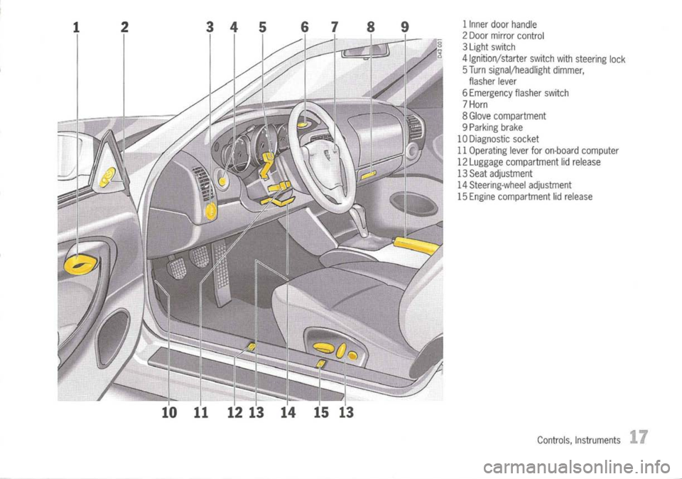
1Inner doorhandle
2 Door mirror control
3 Light switch
4 Ignition/starter switchwithsteering lock
5 Turn signal/headlight dimmer,
flasher lever
6 Emergency flasherswitch
7 Horn
8 Glove compartment
9 Parking brake
10 Diagnostic socket
11 Operating leverforon-board computer
12 Luggage compartment lidrelease
13 Seat adjustment
14 Steering-wheel adjustment
15 Engine compartment lidrelease
Controls, Instruments
17
Page 31 of 195
SeatAdjustment
/!\
Warning!
The seat may move unexpectedly ifyou
attempt toadjust whiledriving. Thiscould
cause sudden lossofcontrol orpersonal in-
jury.
~ Donot adjust seatswhilethevehicle isin mo-
tion.
The backrest locksmustbeengaged atall
times whilethevehicle isinmotion.
Safety beltsonlyoffer protection whenthe
backrest isupright andthebelts areproperly
positioned onthe body.
Improperly positionedsafetybeltscancause
serious personal injuryinan accident.
~ Donot operate thecarwith thedriver orpas-
senger backrests excessively reclined
(see "Seat position").
Controls, Instruments
Seat
position
A correct sittingposition isimportant forsafe and
fatigue-free driving.
We recommend thefollowing procedure for
adjusting thedriver's seattosuit individual
requirements:
1. Adjust theseat height togive yourself enough
headroom andagood overview ofthe vehicle.
2. Adjust theseat until, withtheaccelerator pedal
fully depressed, yourlegisstraight butyour
entire footstillrests onthe accelerator pedal.
3. Grip thetop half ofthe steering wheel.
Set thebackrest angleandsteering-wheel
position sothat your arms arealmost
outstretched. However,yourshoulders must
still rest onthe backrest.
4. Ifnecessary, correcttheseat fore-and-aft
adjustment.
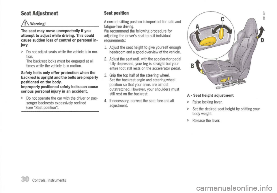
A
-
Seat height adjustment
~ Raise locking lever.
~ Set thedesired seatheight byshifting your
body weight.
~ Release thelever.
Page 32 of 195
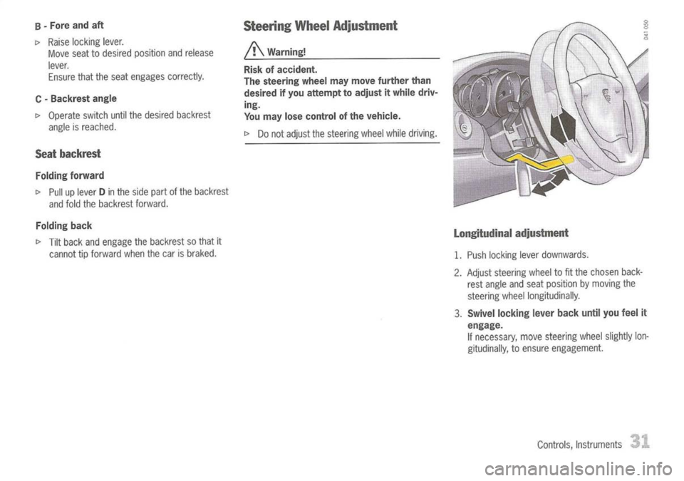
B-Fore andaft
I>
Raise locking lever.
Move seattodesired position andrelease
lever. Ensure thattheseat engages correctly.
C -
Backrest angle
I>
Operate switchuntilthedesired backrest
angle isreached.
Seat backrest
Folding forward
I>
Pull uplever Dinthe side partofthe backrest
and fold thebackrest forward.
Folding back
I>
Tilt back andengage thebackrest sothat it
cannot tipforward whenthecar isbraked.
Steering
WheelAdjustment
A
Warning!
Risk ofaccident.
The steering wheelmaymove further than
desired ifyou attempt toadjust itwhile driv-
ing.
You may losecontrol ofthe vehicle.
I>
Donot adjust thesteering wheelwhiledriving.
Longitudinal adjustment
1. Push locking leverdownwards.
2. Adjust steering wheelto
fit
the chosen back-
rest angle andseat position bymoving the
steering wheellongitudinally.
3. Swivel locking leverbackuntilyoufeel it
engage.
If
necessary, movesteering wheelslightly lon-
gitudinally, toensure engagement.
Controls, Instruments
Page 35 of 195
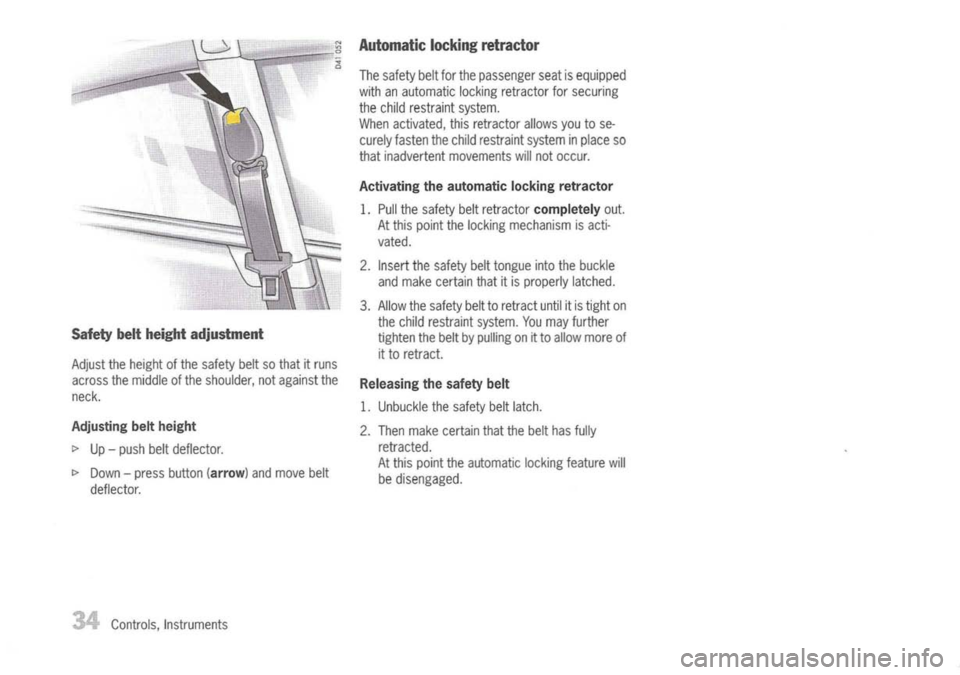
Safetybeltheight adjustment
Adjust theheight ofthe safety beltsothat itruns
across themiddle ofthe shoulder, notagainst the
neck.
Adjusting beltheight
I>
Up-push beltdeflector.
I>
Down -press button
(arrow)
andmove belt
deflector.
34
Controls, Instruments
Automatic
lockingretractor
The safety beltforthe passenger seatisequipped
with anautomatic lockingretractor forsecuring
the child restraint system.
When activated, thisretractor allowsyoutose-
curely fasten thechild restraint systeminplace so
that inadvertent movements willnot occur.
Activating theautomatic lockingretractor
1. Pull thesafety beltretractor
completely
out.
At this point thelocking mechanism isacti-
vated.
2. Insert thesafety belttongue intothebuckle
and make certain thatitis properly latched.
3. Allow thesafety belttoretract untilitis tight on
the child restraint system.Youmay further
tighten thebelt bypulling onitto allow more of
it to retract.
Releasing thesafety belt
1. Unbuckle thesafety beltlatch.
2. Then make certain thatthebelt hasfully
retracted.
At this point theautomatic lockingfeature will
be disengaged.
Page 168 of 195
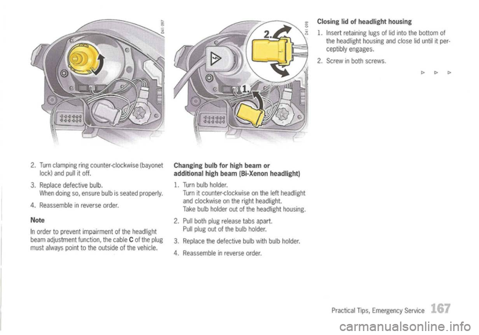
2.Turn clamping ringcounter-clockwise (bayonet
lock) andpullitoff.
3. Replace defective bulb.
When doing so,ensure bulbisseated properly.
4. Reassemble inreverse order.
Note
In order toprevent impairment ofthe headlight
beam adjustment function,thecable Cof the plug
must always pointtothe outside ofthe vehicle.
Changing
bulbforhigh beam or
additional highbeam (Bi-Xenon headlight)
1. Turn bulbholder.
Turn itcounter-clockwise onthe leftheadlight
and clockwise onthe right headlight.
Take bulbholder outofthe headlight housing.
2. Pull both plugrelease tabsapart.
Pull plug outofthe bulb holder.
3. Replace thedefective bulbwith bulb holder.
4. Reassemble inreverse order.
Closing
lidofheadlight housing
1. Insert retaining lugsoflid into thebottom of
the headlight housingandclose liduntil itper-
ceptibly engages.
2. Screw inboth screws.
[>[>[>
Practical Tips,Emergency Service
.1.67
Page 176 of 195
Adjusting Headlights
c>
Please observe thechapter "LIGHTS, REPLAC-
ING BULBS" onPage 162.
Adjustment
The adjustment ismade withthevehicle readyto
drive andthefuel tank completely filled.
The driver's seatmust beloaded byaperson ora
165 Ibs.(75kg)weight andthetire pressures
must meet theprescribed values.
After being loaded, thecarmust berolled afew
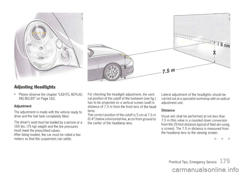
meters sothat thesuspension cansettle. For
checking theheadlight adjustment, theverti-
cal position ofthe cutoff ofthe lowbeam (seefig.)
has tobe projected onavertical screen(wall)in
distance of7.5 mfrom thefront lensofthe head-
lamp.
The correct position ofthe cutoff is5cm at7.5 m
(0.4°) below ahorizontal line,xcm from ground to
the center ofthe headlamp lens. Lateral
adjustment ofthe headlights shouldbe
carried outataspecialist workshop withanoptical
adjustment unit.
Distance
Visual aimshall beperformed atnot less than
7.5 m(this value isarounded downconversion
from the25-foot distance typicaloffield aimusing
a screen). The7.5mdistance ismeasured from
the headlamp lenstothe viewing screen.
c> c>c>
Practical Tips,Emergency Service
175