heating PORSCHE 944 1987 1.G Owners Manual
[x] Cancel search | Manufacturer: PORSCHE, Model Year: 1987, Model line: 944, Model: PORSCHE 944 1987 1.GPages: 66, PDF Size: 3.3 MB
Page 3 of 66

INDEX
A
ABS Acceleration diagram Accelerator pedal Air Bag System Air - cleaner
- conditioner
- filter
Alternator warning light Antifreeze Antilock, Brake system Anti-theft alarm Ashtray Automatic- garage door
- speed control
- transmission
- transmission fluid B
Battery
Boost pressure gauge
Brake - booster
- fluid
- fluid warning light
- pads
- parking
- pedal
- system
- warning light
Break-in hints
Bulb replacing
Buzzer 28,39
118-129
55
20, 21, 38, 3980, 8144-4680,81 39
74,75,11028, 39
11
42, 98
25
29
53-55
78,110,128
90-9234
27
39,79,11039
27,37,47,79,80 26
26, 27
26,27,11537
47
93-98
10,18,24,30
C/D
CASIS
Capacities
Car care instructions
Casis
Catalytic Converter
Cautions
Central locking
Central warning light
Cigarette lighter
Cleaning
Clock
Clutch pedal
Collapsible spare tire
Control warning light system
Coolant Temperature Gauge
Cooling system
Corrosion prevention
Dashboard
Defogging/defrosting
Dimensions
Doors
Driving hints
E/F
Electrical system
Emergency- flasher
- starting
Emission Control System
Engine - cooling
- exhaust
- hood
- number
- oil checking & changing
- oil
-speed, max 35
110
61-66
35
50,10267
13
37
41
61-66 40
27
85
36-39 36
74-77
65-66
24
44-46 114
12,138-9, 48, 49
89-92
41
92
100-103 74-77
48
586
69-72
69,110,111,128
34,47,52,106-
108
Fan control switch knob
Fan, radiator
Filling capacities
Fog lights
Fuel - economy
- evaporation control
- gauge
- recommendation
- tank
Fuses and relays
G/H
Gas Station Information
Gasohol
Gasoline
Gear ratio diagram
Gearshift lever
Glove compartment
Hatchback
Headlights
Headlight- dimmer
- flasher
- switch
- washing system
Heater/ventilation controls
Hood - front
- rear
Horn
I/J
Ignition/steering lock
Instrument illumination
Instruments
Interior ligh 44
36, 74 110
30, 96, 97
49
103 37
50, 51
50,110
89,126
126-129 51
50,51
122-125 52-55
42
56
30,95,99 30
30
30
31,32,81,11044-4658
56,57
21,24
24
30
33-40
43, 98
4
Jack
- supports
K/L
Keys
Kickdown
Lane changer
Leather
License plate light
Light switch
Lights - ashtray
- fog
- interior
- license plate
- parking
- turn signal
Locks - doors, wheels
Loudspeakers
Lubricants
Luggage compartment
M/O
Manual transmission
- oil
Mirrors
Oil- change
- consumption
- filter changing
- pressure gauge
- pressure warning light
Octane rating
Oxygen Sensor
P/R
Paint code number 68
87, 88, 129
10-11,86 55
30
65
98
30
98
30, 96, 97
43, 9898
30, 37, 93, 94
30,93,94
10-13, 86 89
110,111 57
52,122-125 77,11022,43
71,72
47, 69
71, 72 38
38
50, 51,106-108 101,102
7
Parking- brake
- lights
Performance
Power assisted steering
Power train
Power windows
Prop-up roof
Radiator fan
Rear - hood
- view mirrors
- window defogger
- wiper
Recirculation Switch
Refrigerant
Relays
Rims
Roof racks
Roof, removable S
Safe driving hints
Safetybelts
Safety belt warning light
Safety compliance sticker
Seat heating System
Seats
Sekuriflex windshield
Shift indicator
Shift points
Side marker lights
Ski racks
Snow- chains
- tires
Spare tire, collapsible
Spark plugs
Specifications, engine
26, 3730,37,93,94116731091259, 6036, 7456,572241424446,11089,12664,112,11357,11459, 60
8-9
17-21,6518,3771514-1631, 63, 643552-559457,11483, 84,112,113
83,84, 111,113
85106-108106-109
Speedometer
Starting procedures
Sun visors
T/U
Tachometer
Technical data
Tirepressure
Tires
Tool kit
Trip odometer
Transmission oil
Trunk
Turn signal lights
Undercoating
Unleaded fuel
V/W
Vehicle identification
Ventilation
Voltmeter
Warning/indicator lights
Washer reservoir
Washing
Water temperature gauge
Weatherstrips
Weights
Wheel alignment
Wheel nuts, lockable
Wheels
Wheel changing
Windows
Windshield- washer reservoir
- wiper/washer lever 3324, 2543
34, 35105-12582,112,113,12947,82-87,112,113683377, 78,11056,5730, 37, 93, 9465, 66,10050, 51,106-108,110
6-744-463835-4081,11061-6636641141158647,64,82-87,11285-8812,63,6481,11031
5
Page 8 of 66
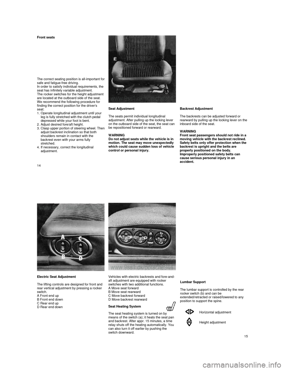
Front seats
The correct seating position is all-
important for safe and fatigue-free driving.
In order to satisfy individual requirements, the
seat has infinitely variable adjustment.
The rocker switches for the height adjustment
are located at the outboard side of the seat.
We recommend the following procedure for
finding the correct position for the driver's
seat:
1. Operate longitudinal adjustment until your leg is fully stretched with the clutch pedal
depressed while your foot is bent.
2.
Adjust desired fore/aft height.
3. Clasp upper portion of steering wheel. Then adjust backrest inclination so that both
shoulders remain in contact with the
backrest even with your arms fully
stretched.
4.
If necessary, correct the longitudinal
adjustment.
Seat Adjustment
The seats permit individual longitudinal
adjustment. After pulling up the locking lever
on the outboard side of the seat, the seat can
be repositioned forward or rearward.
WARNING
Do not adjust seats while the vehicle is in
motion. The seat may move unexpectedly
which could cause sudden loss of vehicle
control or personal injury. Backrest Adjustment
The backrests can be adjusted forward or
rea
rward by pulling up the locking lever on the inboard side of the seat.
WARNING
Front seat passengers should not ride in a
moving vehicle with the backrest reclined.
Safety belts only offer protection when the
backrest is upright and the belts are
properly positioned on the body.
Improperly positioned safety belts can
cause serious personal injury in an
accident.
14
Electric Seat Adjustment
The lifting controls are designed for front and
rear vertical adjustment by pressing a rocker
switch.
A Front end up
B Front end down
C Rear end up
D Rear end down
Vehicles with electric backrests and fore-and-
aft adjustment are equipped with rocker
switches with two additional functions.
A Move seat forward
B Move seat rearward
C Move backrest forward
D Move backrest rearward
Seat Heating System
The seat heating system is turned on by
means of the switch (a); it heats the seat pan
and backrest. After appr. 15 minutes, a time
relay shuts off the heating automatically. You
can also turn it off earlier by pushing the
switch downward.
Lumbar Support
The lumbar support is controlled by the rear
rocker switch (b) and can be
extended/retracted or raised/lowered to any
position to support the spine.
Horizontal adjustment
Height adjustment
15
Page 12 of 66
Rear View Mirrors
Do not put decals or other signs on the
windows that may interfere with the driver's
vision.
Adjust the outside and inside mirrors before driving. It is important for safe driving that you have good vision to the rear.
Inside day-night mirror
You can adjust the day-
night mirror from clear daylight visibility to non-glare visibility at night by moving the lever at the bottom of the
mirror forward or rearward.
Heated outside mirrors with remote
control
When you turn on the rear window defogger,
the outside rear view mirror is also heated.
The outside mirrors are ad
justable from inside of the vehicle by a four direction switch
located on the left door and a rocker switch
located on the center console ahead of the
gear selection lever. The rocker switch (A)
selects either the left or right mirror for
adjustment. Push
the rocker switch forward to select the left mirror, and rearward to select
the right mirror. Then the four direction switch
will adjust the selected mirror in any of the four directions.
The mirror housing is hinged and can be
folded flat against the c
ar in either direction to prevent damage in tight parking spots.
If necessary, the outside mirrors can also be
adjusted manually.
22
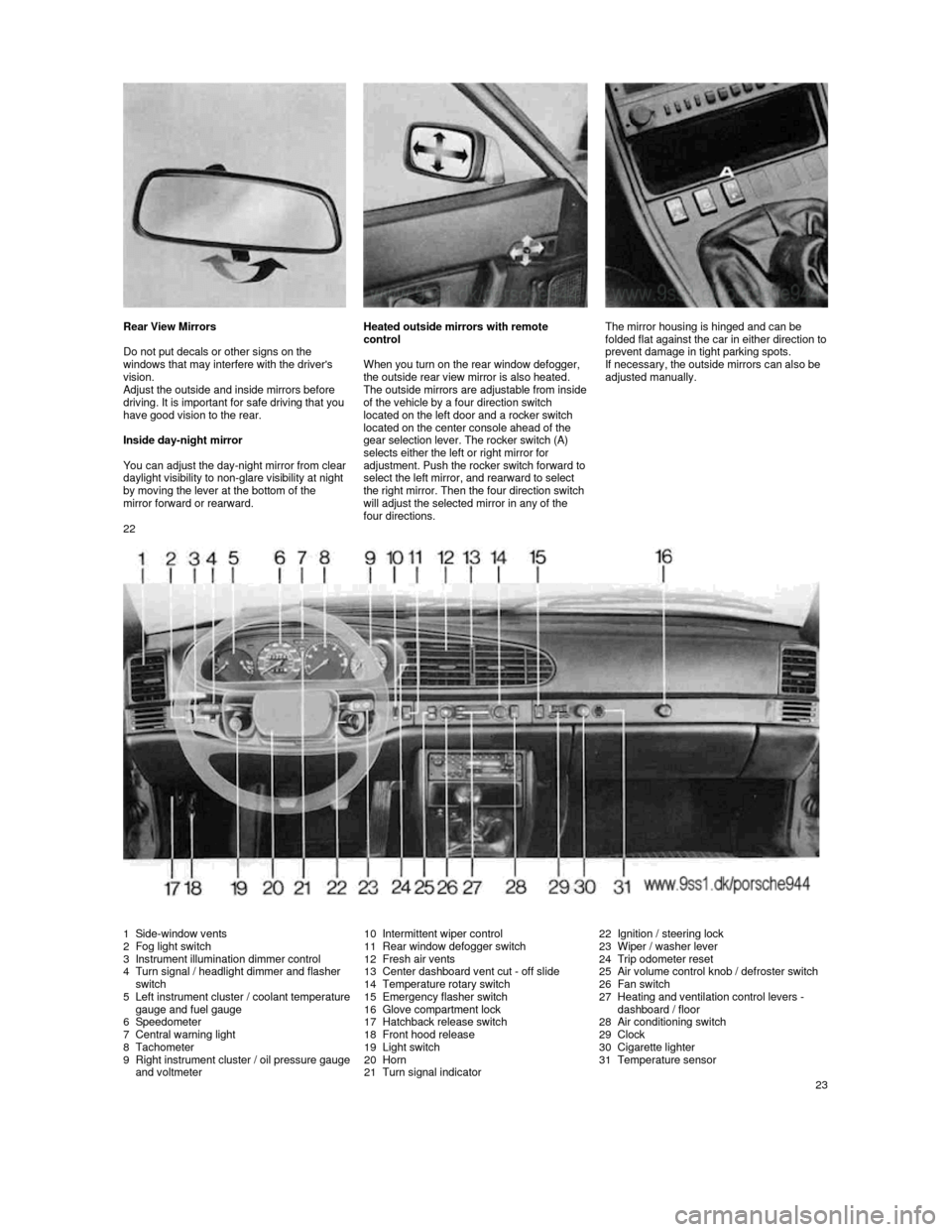
1 Side-window vents 2 Fog light switch
3 Instrument illumination dimmer control
4 Turn signal / headlight dimmer and flasher
switch
5
Left instrument cluster / coolant temperature gauge and fuel gauge
6 Speedometer
7 Central warning light
8 Tachometer
9 Right instrument cluster / oil pressure gauge and voltmeter
10 Intermittent wiper control
11 Rear window defogger switch
12 Fresh air vents
13 Center dashboard vent cut -
off slide14 Temperature rotary switch
15 Emergency flasher switch
16 Glove compartment lock
17 Hatchback release switch
18 Front hood release
19 Light switch
20 Horn
21 Turn signal indicator
22 Ignition / steering lock
23 Wiper / washer lever
24 Trip odometer reset
25
Air volume control knob / defroster switch
26 Fan switch
27 Heating and ventilation control levers -
dashboard / floor
28
Air conditioning switch
29 Clock
30 Cigarette lighter
31 Temperature sensor
23
Page 14 of 66
The brake warning light on the dashboard will go out after the engine is started and the
parking brake is fully released.
WARNING
Release the parking brake fully. A partially engaged brake will overheat the rear
brakes, reduce their effectiveness and
cause excessive wear.
Always set the parking brake when parking your car. Move the selector lever
to "P" (Automatic transmission) or move
the gearshift lever to reverse or first gear
(Manual transmission). On hills also turn
the wheels toward the curb.
WARNING Failure of one brake circuit will impair the
braking capability resulting in an
increased stopping distance.
If one brake circuit has failed, the other will
still operate. However, you will notice an
increased pedal travel when you step on the
brake. Should you encounter such
experience, bring your vehicle safely to a full
stop.
Avoid driving the vehicle and instead have it towed to the nearest authorized Porsche
dealer.
Brake Pedal
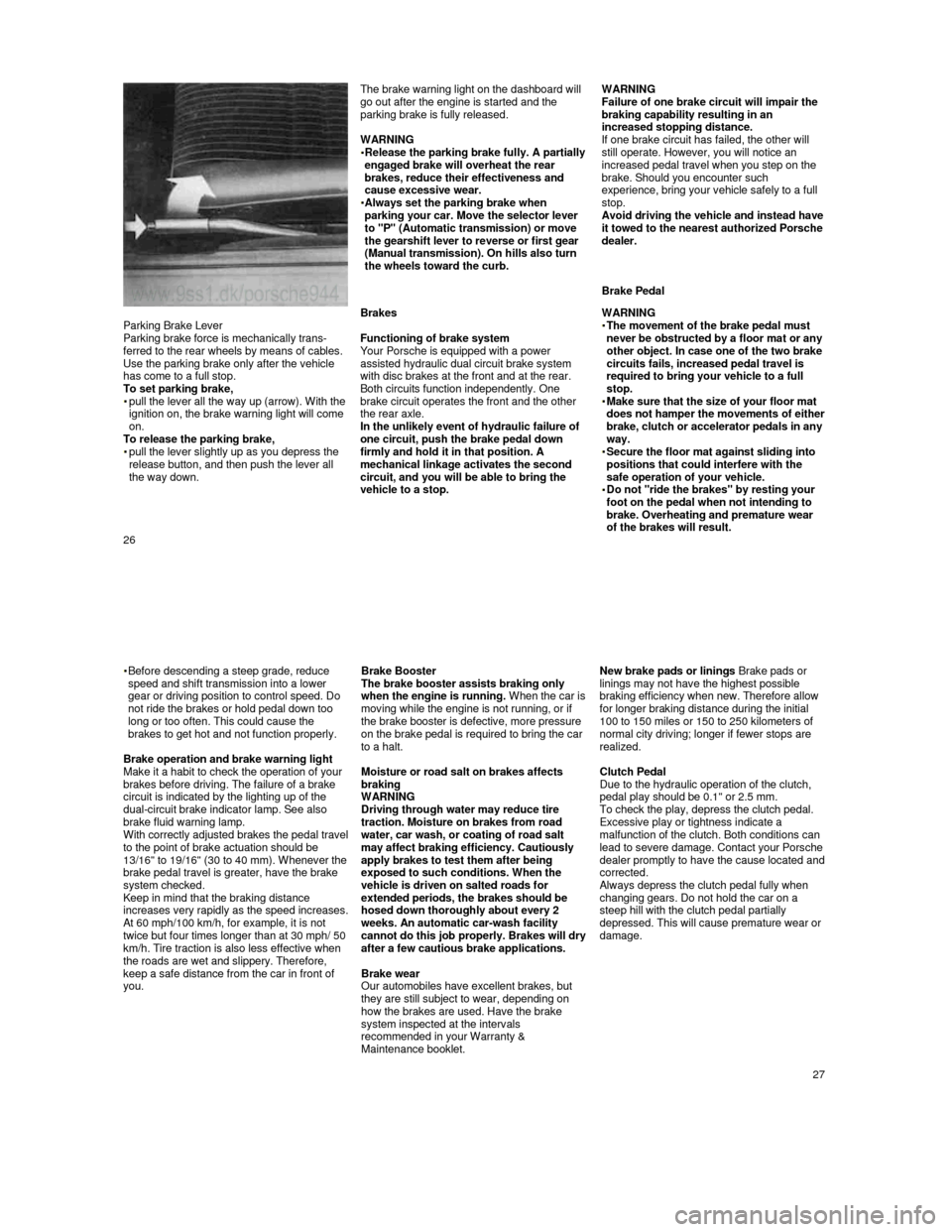
Parking Brake Lever
Parking brake force is mechanically trans-
ferred to the rear wheels by means of cables.
Use the parking brake only after the vehicle
has come to a full stop.
To set parking brake,
pull the lever all the way up (arrow). With the ignition on, the brake warning light will come
on.
To release the parking brake,
pull the lever slightly up as you depress the
release button, and then push the lever all
the way down.
Brakes
Functioning of brake system
Your Porsche is equipped with a power
assisted hydraulic dual circuit brake system
with disc brakes at the front and at the rear. Both circuits function independently. One
brake circuit operates the front and the other
the rear axle.
In the unlikely event of hydraulic failure of
one circuit, push the brake pedal down
firmly and hold it in that position. A
mechanical linkage activates the second
circuit, and you will be able to bring the
vehicle to a stop.
WARNING
The movement of the brake pedal must never be obstructed by a floor mat or any
other object. In case one of the two brake
circuits fails, increased pedal travel is
required to bring your vehicle to a full
stop.
Make sure that the size of your floor mat does not hamper the movements of either brake, clutch or accelerator pedals in any
way.
Secure the floor mat against sliding into positions that could interfere with the
safe operation of your vehicle.
Do not "ride the brakes" by resting your foot on the pedal when not intending to
brake. Overheating and premature wear
of the brakes will result.
26
Before descending a steep grade, reduce
speed and shift transmission into a lower
gear or driving position to control speed. Do
not ride the brakes or hold pedal down too
long or too often. This could cause the
brakes to get hot and not function properly.
Brake operation and brake warning light
Make it a habit to check the operation of your
brakes before driving. The failure of a brake
circuit is indicated by the lighting up of the
dual-circuit brake indicator lamp. See also
brake fluid warning lamp.
With correctly adjusted brakes the pedal travel to the point of brake actuation should be
13/16" to 19/16" (30 to 40 mm). Whenever the brake pedal travel is greater, have the brake
system checked.
Keep in mind that the braking distance
increases very rapidly as the speed increases. At 60 mph/100 km/h, for example, it is not twice but four times longer than at 30 mph/ 50
km/h. Tire traction is also less effective when
the roads are wet and slippery. Therefore,
keep a safe distance from the car in front of
you.
Brake Booster The brake booster assists braking only
when the engine is running. When the car is moving while the engine is not running, or if
the brake booster is defective, more pressure
on the brake pedal is required to bring the car
to a halt.
Moisture or road salt on brakes affects
braking
WARNING
Driving through water may reduce tire
traction. Moisture on brakes from road
water, car wash, or coating of road salt
may affect braking efficiency. Cautiously
apply brakes to test them after being
exposed to such conditions. When the
vehicle is driven on salted roads for
extended periods, the brakes should be
hosed down thoroughly about every 2
weeks. An automatic car-wash facility
cannot do this job properly. Brakes will dry after a few cautious brake applications.
Brake wear
Our automobiles have excellent brakes, but
they are still subject to wear, depending on
how the brakes are used. Have the brake
system inspected at the intervals
recommended in your Warranty &
Maintenance booklet.
New brake pads or linings Brake pads or
linings may not have the highest possible
braking efficiency when new. Therefore allow
for longer braking distance during the initial
100 to 150 miles or 150 to 250 kilometers of
normal city driving; longer if fewer stops are
realized.
Clutch Pedal
Due to the hydraulic operation of the clutch,
pedal play should be 0.1" or 2.5 mm.
To check the play, depress the clutch pedal.
Excessive play or tightness indicate a
malfunction of the clutch. Both conditions can
lead to severe damage. Contact your Po
rsche dealer promptly to have the cause located and corrected. Always depress the clutch pedal fully when changing gears. Do not hold the car on a
steep hill with the clutch pedal partially
depressed. This will cause premature wear or
damage.
27
Page 19 of 66
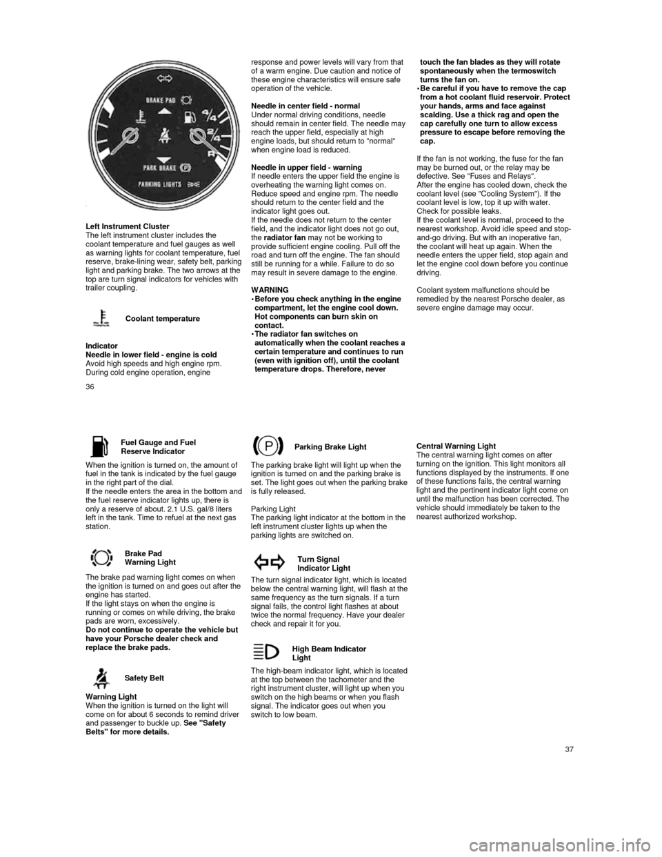
Left Instrument Cluster
The left instrument cluster includes the
coolant temperature and fuel gauges as well
as warning lights for coolant temperature, fuel
reserve, brake-
lining wear, safety belt, parking light and parking brake. The two arrows at the
top are turn signal indicators for vehicles with
trailer coupling.
Coolant temperature
Indicator
Needle in lower field - engine is cold
Avoid high speeds and high engine rpm. During cold engine operation, engine
response and power levels will vary from that
of a warm engine. Due caution and notice of
these engine characteristics will ensure safe
operation of the vehicle.
Needle in center field - normal
Under normal driving conditions, needle
should remain in center field. The needle may
reach the upper field, especially at high
engine loads, but should return to "normal"
when engine load is reduced.
Needle in upper field - warning
If needle enters the upper field the engine is
overheating the warning light comes on.
Reduce speed and engine rpm. The needle
should return to the center field and the
indicator light goes out.
If the needle does not return to the center
field, and the indicator light does not go out,
the radiator fan may not be working to
provide sufficient engine cooling. Pull off the
road and turn off the engine. The fan should
still be running for a while. Failure to do so
may result in severe damage to the engine.
WARNING
Before you check anything in the engine compartment, let the engine cool down.
Hot components can burn skin on
contact. The radiator fan switches on automatically when the coolant reaches a
certain temperature and continues to run
(even with ignition off), until the coolant
temperature drops. Therefore, never
touch the fan blades as they will rotate spontaneously when the termoswitch
turns the fan on.
Be careful if you have to remove the cap from a hot coolant fluid reservoir. Protect
your hands, arms and face against
scalding. Use a thick rag and open the
cap carefully one turn to allow excess
pressure to escape before removing the
cap.
If the fan is not working, the fuse for the fan
may be burned out, or the relay may be
defective. See "Fuses and Relays".
After the engine has cooled down, check the coolant level (see "Cooling System"). If the
coolant level is low, top it up with water.
Check for possible leaks.
If the coolant level is normal, proceed to the
nearest workshop. Avoid idle speed and stop-
and-go driving. But with an inoperative fan,
the coolant will heat up again. When the
needle enters the upper field, stop again and
let the engine cool down before you continue
driving.
Coolant system malfunctions should be
remedied by the nearest Porsche dealer, as
severe engine damage may occur.
36
Fuel Gauge and FuelReserve Indicator
When the ignition is turned on, the amount of
fuel in the tank is indicated by the fuel gauge
in the right part of the dial.
If the needle enters the area in the bottom and the fuel reserve indicator lights up, there is
only a reserve of about. 2.1 U.S. gal/8 liters
left in the tank. Time to refuel at the next gas
station.
Brake Pad
Warning Light
The brake pad warning light comes on when the ignition is turned on and goes out after the engine has started.
If the light stays on when the engine is
running or comes on while driving, the brake
pads are worn, excessively.
Do not continue to operate the vehicle but
have your Porsche dealer check and
replace the brake pads.
Safety Belt
Warning Light
When the ignition is turned on the light will
come on for about 6 seconds to remind driver
and passenger to buckle up. See "Safety
Belts" for more details.
Parking Brake Light
The parking brake light will light up when the
ignition is turned on and the parking brake is
set.
The light goes out when the parking brake is fully released.
Parking Light
The parking light indicator at the bottom in the
left instrument cluster lights up when the
parking lights are switched on.
Turn Signal
Indicator Light
The turn signal indicator light, which is located below the central warning light, will flash at the same frequency as the turn signals. If a turn
signal fails, the control light flashes at about
twice the normal frequency. Have your dealer
check and repair it for you.
High Beam Indicator
Light
The high-beam indicator light, which is located at the top between the tachometer and the
right instrument cluster, will light up when you
switch on the high beams or when you flash
signal. The indicator goes out when you
switch to low beam.
Central Warning Light
The central warning light comes on after
turning on the ignition. This light monitors all
functions displayed by the instruments. If one
of these functions fails, the central warning
light and the pertinent indicator light come on
until the malfunction has been corrected. The
vehicle should immediately be taken to the
nearest authorized workshop.
37
Page 23 of 66
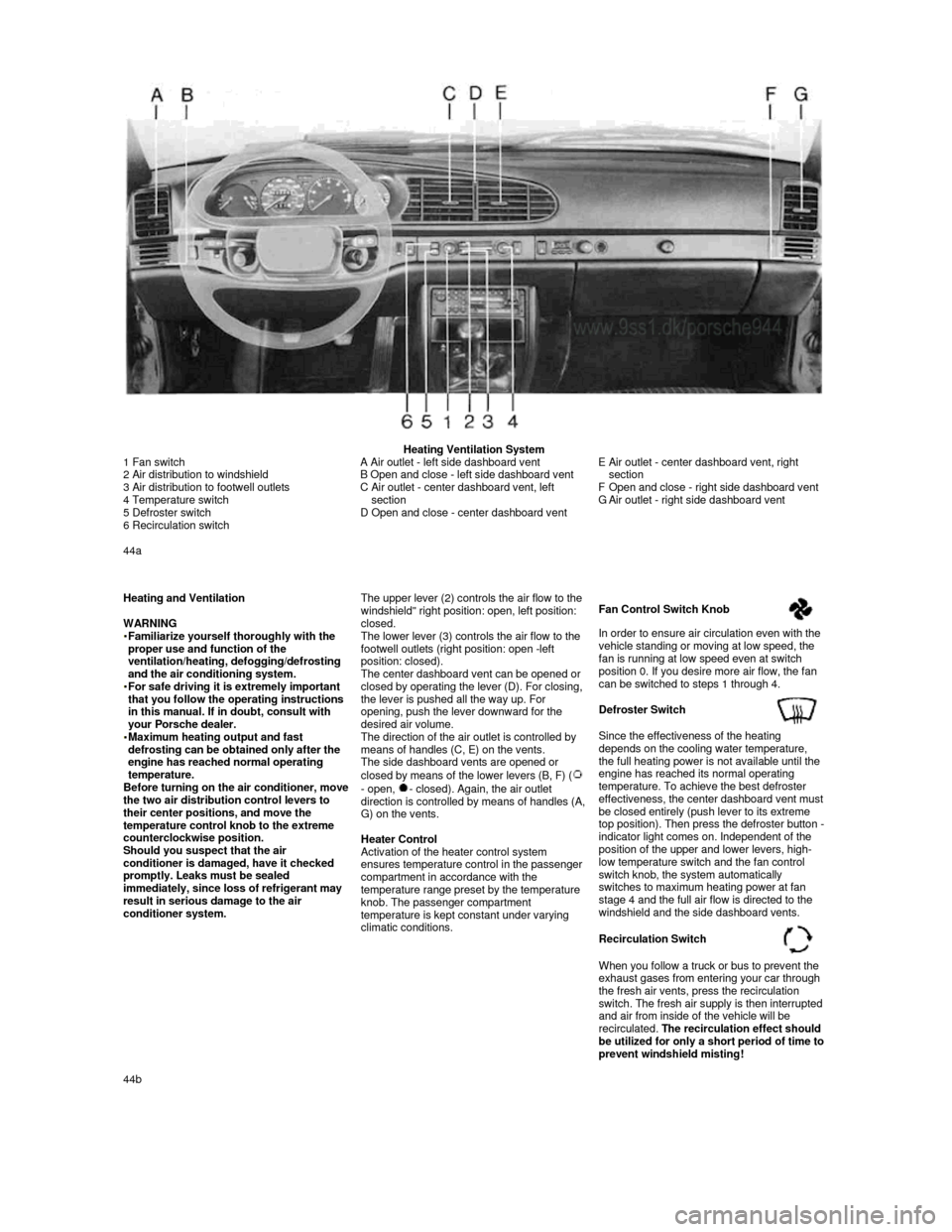
Heating Ventilation System
1 Fan switch
2 Air distribution to windshield
3 Air distribution to footwell outlets
4 Temperature switch
5 Defroster switch
6 Recirculation switch
A Air outlet - left side dashboard vent
B Open and close - left side dashboard vent
C
Air outlet - center dashboard vent, left
section
D Open and close - center dashboard vent
E Air outlet - center dashboard vent, right
section
F
Open and close - right side dashboard vent
G Air outlet - right side dashboard vent
44a
Heating and Ventilation
WARNING
Familiarize yourself thoroughly with the proper use and function of the
ventilation/heating, defogging/defrosting
and the air conditioning system.
For safe driving it is extremely important that you follow the operating instructions
in this manual. If in doubt, consult with
your Porsche dealer.
Maximum heating output and fast defrosting can be obtained only after the
engine has reached normal operating
temperature.
Before turning on the air conditioner, move the two air distribution control levers to
their center positions, and move the
temperature control knob to the extreme
counterclockwise position.
Should you suspect that the air
conditioner is damaged, have it checked
promptly. Leaks must be sealed
immediately, since loss of refrigerant may
result in serious damage to the air
conditioner system.
The upper lever (2) controls the air flow to the windshield" right position: open, left position: closed.
The lower lever (3) controls the air flow to the
footwell outlets (right position: open -left
position: closed).
The center dashboard vent can be opened or
closed by operating the lever (D). For closing,
the lever is pushed all the way up. For
opening, push the lever downward for the
desired air volume.
The direction of the air outlet is controlled by
means of handles (C, E) on the vents.
The side dashboard vents are opened or
closed by means of the lower levers (B, F) (
- open, - closed). Again, the air outlet direction is controlled by means of handles (A, G) on the vents.
Heater Control
Activation of the heater control system ensures temperature control in the passenger
compartment in accordance with the
temperature range preset by the temperature
knob. The passenger compartment
temperature is kept constant under varying
climatic conditions.
Fan Control Switch Knob
In order to ensure air circulation even with the
vehicle standing or moving at low speed, the
fan is running at low speed even at switch
position 0. If you desire more air flow, the fan
can be switched to steps 1 through 4.
Defroster Switch
Since the effectiveness of the heating
depends on the cooling water temperature,
the full heating power is not available until the
engine has reached its normal operating
temperature. To achieve the best defroster
effectiveness, the center dashboard vent must be closed entirely (push lever to its extreme
top position). Then press the defroster button - indicator light comes on. Independent of the
position of the upper and lower levers, high-
low temperature switch and the fan control
switch knob, the system automatically
switches to maximum heating power at fan
stage 4 and the full air flow is directed to the
windshield and the side dashboard vents.
Recirculation Switch
When you follow a truck or bus to prevent the
exhaust gases from entering your car through
the fresh air vents, press the recirculation
switch. The fresh air supply is then interrupted and air from inside of the vehicle will be
recirculated. The recirculation effect should
be utilized for only a short period of time to prevent windshield misting! 44b
Page 38 of 66
Power Assisted Steering
The hydraulic assistance system allows
effortless steering under all driving conditions.
Slight hissing or squeaking sounds during
sharp turns (turning steering wheel from lock
to lock) are normal and do not indicate a
defective steering mechanism.
If the engine is not running, po
wer assisted steering is no longer effective. You can
continue to steer the car but more effort
will be required to turn the steering wheel.
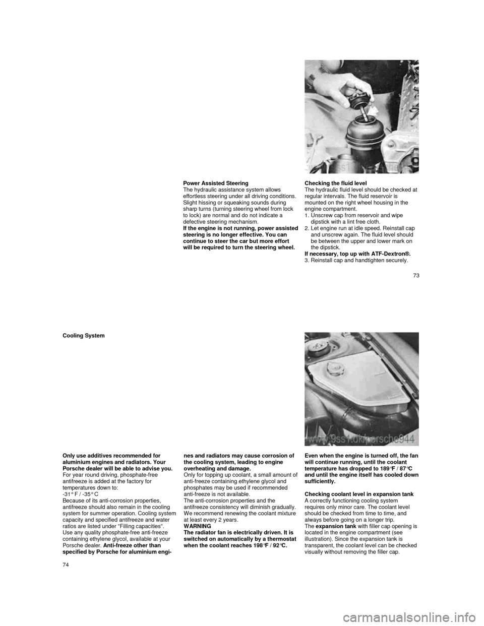
Checking the fluid level
The hydraulic fluid level should be checked at
regular intervals. The fluid reservoir is
mounted on the right wheel housing in the
engine compartment.
1.
Unscrew cap from reservoir and wipe
dipstick with a lint free cloth.
2.
Let engine run at idle speed. Reinstall cap
and unscrew again. The fluid level should
be between the upper and lower mark on
the dipstick.
If necessary, top up with ATF-Dextron®.
3. Reinstall cap and handtighten securely.
73
Cooling System
Only use additives recommended for
aluminium engines and radiators. Your
Porsche dealer will be able to advise you.
For year round driving, phosphate-free
antifreeze is added at the factory for
temperatures down to:
-31° F / -35° C
Because of its anti-corrosion properties,
antifreeze should also remain in the cooling
system for summer operation. Cooling system capacity and specified antifreeze and water
ratios are listed under "Filling capacities".
Use any quality phosphate-free anti-freeze
containing ethylene glycol, available at your
Porsche dealer. Anti-freeze other than
specified by Porsche for aluminium engi-
nes and radiators may cause corrosion of
the cooling system, leading to engine
overheating and damage.
Only
for topping up coolant, a small amount of anti-freeze containing ethylene glycol and
phosphates may be used if recommended
anti-freeze is not available.
The anti-corrosion properties and the
antifreeze consistency will diminish gradually.
We recommend renewing the coolant mixture
at least every 2 years.
WARNING
The radiator fan is electrically driven. It is
switched on automatically by a thermostat
when the coolant reaches 198°F / 92°C.
Even when the engine is turned off, the fan will continue running, until the coolant
temperature has dropped to 189°F / 87°C
and until the engine itself has cooled down sufficiently.
Checking coolant level in expansion tank
A correctly functioning cooling system requires only minor care. The coolant level
should be checked from time to time, and
always before going on a longer trip.
The
expansion tank with filler cap opening is
located in the engine compartment (see
illustration). Since the expansion tank is
transparent, the coolant level can be checked
visually without removing the filler cap.
74
Page 51 of 66
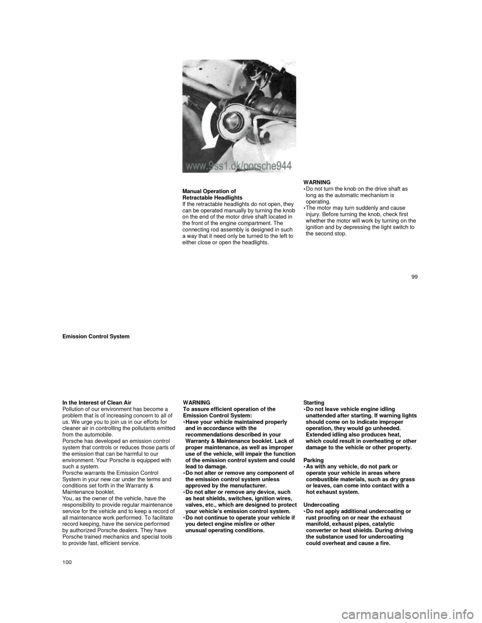
Manual Operation of
Retractable Headlights
If the retractable headlights do not open, they
can be operated manually by turning the knob
on the end of the motor drive shaft located in
the front of the engine compartment. The
connecting rod assembly is designed in such
a way that it need only be turned to the left to
either close or open the headlights.
WARNING
Do not turn the knob on the drive shaft as
long as the automatic mechanism is
operating.
The motor may turn suddenly and cause
injury. Before turning the knob, check first
whether the motor will work by turning on the ignition and by depressing the light switch to
the second stop.
99
Emission Control System
In the Interest of Clean Air
Pollution of our environment has become a
problem that is of increasing concern to all of
us. We urge you to join us in our efforts for
cleaner air in controlling the pollutants emitted from the automobile.
Porsche has developed an emission control
system that controls or reduces those parts of
the emission that can be harmful to our
environment. Your Porsche is equipped with
such a system.
Porsche warrants the Emission Control
System in your new car under the terms and
conditions set forth in the Warranty &
Maintenance booklet.
You, as the owner of the vehicle, have the
responsibility to provide regular maintenance
service for the vehicle and to keep a record of
all maintenance work performed. To facilitate
record keeping, have the service performed
by authorized Porsche dealers. They have
Porsche trained mechanics and special tools
to provide fast, efficient service.
WARNING To assure efficient operation of the
Emission Control System:
Have your vehicle maintained properly and in accordance with the
recommendations described in your
Warranty & Maintenance booklet. Lack of
proper maintenance, as well as improper
use of the vehicle, will impair the function
of the emission control system and could
lead to damage.
Do not alter or remove any component of the emission control system unless
approved by the manufacturer.
Do not alter or remove any device, such as heat shields, switches, ignition wires, valves, etc., which are designed to protect your vehicle's emission control system. Do not continue to operate your vehicle if you detect engine misfire or other
unusual operating conditions.
Starting
Do not leave vehicle engine idling unattended after starting. If warning lights should come on to indicate improper
operation, they would go unheeded.
Extended idling also produces heat,
which could result in overheating or other damage to the vehicle or other property.
Parking
As with any vehicle, do not park or operate your vehicle in areas where
combustible materials, such as dry grass
or leaves, can come into contact with a
hot exhaust system.
Undercoating
Do not apply additional undercoating or rust proofing on or near the exhaust
manifold, exhaust pipes, catalytic
converter or heat shields. During driving
the substance used for undercoating
could overheat and cause a fire.
100
Page 52 of 66
How Emission Control Works
When an automobile engine is running, it uses energy generated through the combustion of a mixture of air and fuel. Depending on whether
a car is driven fast or slowly or whether the
engine is cold or hot, some of the fuel
(hydrocarbons) may not be burned completely but be discharged into the engine crankcase
or exhaust system. Additional hydrocarbons
may enter the atmosphere through
evaporation of fuel from the fuel tank. These
hydrocarbons (HC), when released into the
air, contribute to undesirable pollution.
In addition, carbon monoxide (CO) and oxides of nitrogen (NOx) contribute to engine
emissions. They, too, are formed during the
combustion process and discharged into the
exhaust system.
To reduce these pollutants, your Porsche is
equipped with a precisely calibrated fuel
injection system to assure a finely balanced
air/fuel mixture under all operating conditions.
Oxygen Sensor
The oxygen sensor, installed in the exhaust
pipe continuously senses the oxygen content
of the exhaust and signals the information to
an electronic control unit. The control unit
corrects the air/fuel ratio, so that the engine
always receives an accurately metered air fuel mixture. .
Crankcase Ventilation
Through Crankcase Ventilation undesirable
emissions from the engine crankcase are not
permitted to reach the outside atmosphere.
These emissions are recirculated from the
crankcase to the air intake system. From here
the emissions mix with the intake air and are
later burned in the engine.
Catalytic converter
The catalytic converter is an efficient
"cleanup" device built into the exhaust system
of the vehicle. The catalytic converter burns
the undesirable pollutants in the exhaust gas
before it is released into the atmosphere.
The exclusive use of unleaded fuel is critically important for the life of the
catalytic converter. Therefore, only
unleaded gasoline without additives must
be used.
The catalytic converter will be damaged by
push or tow starting your vehicle
misfiring of the engine turning off the ignition while the vehicle is moving or
by other unusual operating conditions.
Do not continue to operate your vehicle
under these conditions, as otherwise fuel
can reach the catalytic converter. This
could result in overheating of the
converter.
Federal law prohibits use of leaded
gasoline in this car.
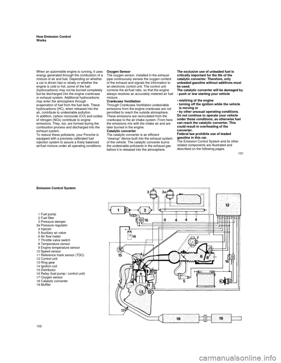
The Emission Control System and its other
related components are illustrated and
described on the following pages.
101
Emission Control System
1 Fuel pump
2 Fuel filter
3 Pressure damper
3a Pressure regulator
4 Injector
5 Auxiliary air valve
6 Air flow meter
7 Throttle valve switch
8 Temperature sensor
9 Engine temperature sensor
10 Speed sensor
11 Reference mark sensor (TDC)
12 Control unit
13 Ring gear
14 Ignition coil
15 Distributor
16 Relay (fuel pump / control unit)
17 Oxygen sensor
18 Catalytic converter
19 Muffler
102
Page 56 of 66

Engine Design Specifications
Design
Operating cycle
Lubrication
Cylinder block
Cylinder head
Valve operation
Camshaft drive
Crankshaft
Fuel injection 4-cylinder, in-line engine, front mount with two ba
lance-shafts
4-stroke
Pressure oil circulation from oil sump,
full flow filter
Light metal
Light metal
Overhead camshaft
(944 S: 2 overhead camshafts)
Spur belt drive
Forged, 5 main bearings
AFC (Air Flow Control) Power Train
Manual transmission
Gear ratio
1st gear
2nd gear
3rd gear
4th gear
5th gear
Axle ratio Gear ratio 944
3.600:1
2.125:1
1.458:1
1.071:1
0.730:1
3.500:1
3.889:1 Gear ratio 944 S
3.500:1
2.059:1
1.400:1
1.034:1
0.829:1
3.500:1
3.889:1 Gear ratio 944 Turbo
3.500:1
2.059:1
1.400:1
1.034:1
0.829:1
3.500:1
3.375:1
Clutch
Power transmission Single plate dry disc, hydraulically operated
Double constant velocity joints and drive shaft
Automatic transmission 944
Gear ratio 1st gear
2nd gear
3rd gear
Reverse gear
Axle ratio
Clutch 2.714:1
1.500:1
1.000:1
2.429:1
3.455:1
Hydrodynamic torque converter
109
Filling Capacities
Engine oil With filter change approx. 6.34 (Turbo: approx. 6.87) U.S. qts. or 6 (Turbo: approx. 6.5) liters.
Check oil level with dipstick a few minutes after e ngine has stopped. The difference between
the max. and min. marks on the dipstick is approx. 1 U.S. qt. or 1 liter.
Only use brand name oil which has been tested and a pproved by Porsche.
Your authorized Porsche dealer will be glad to advi se you.
Porsche does not recommend the use of oil additives . See also "Engine Oils".
Cooling system with heating
Approx. 8,2 U.S. qts. or 7,8 liters. Factory filled to -31°F (-35°C). Only use phosphate-free
anti-freeze containing ethylene glycol recommended for aluminum engines and radiators.
Manual transmission
Approx. 0.53 U.S. gal. or 2.0 liters. Use hypoid oi l SAE 80 labeled "For Service API/GL4 or
Mil-L 2105".
Automatic transmission with
torque converter Approx. 1.72 U.S. gal. or 6.5 liters ATF Dexron®. At oil c hanges 3 U.S. qts. or 2.8 liters are
required.
Differential of automatic transmission
Approx. 1 U.S. qts. or 1 liter hypoid oil SAE 90 ac cording to API classification GL 5 or
Mil-L 2105 B.
Power steering
Approx. 0.63 U.S. qts. or 0.6 liter ATF Dexron®
Fuel tank Approx. 21.1 U.S. gals, or 80 liters including a re serve of 2.1 U.S. gals, or 8 liters.
Unleaded fuel only! Minimum octane rating 944 91 RO N (87 CLC or AKI ((R+M)/2) rating on fuel
pumps in U.S.A.), 944 S / 944 Turbo 95 RON (90 CLC or AKI ((R+M)/2) rating on fuel pumps in U.S.A.)
Brake fluid Approx. 0.42 U.S. pint or 0.2 liter. Only use brake fluid conforming to specifications
SAE J 1703, DOT 3 or DOT 4.
Windshield and headlight washer system
Approx. 1.59 U.S. gals, or 6.0 liters.
Refrigerant for air conditioning Approx. 33.5 oz or 950 g. Refrigerant R 12 (CCI2F2)
Cooling system mixing chart
(Approximate values)
Anti-freeze-Water
Consult your authorized dealer about
the approved anti-freeze mixtures. Temp, down to
-13° F (-25°C) -23° F (-30° C) -31° F (-35° C)
Anti-freeze
40%
45%
50% Water
60% 55% 50%
Anti-freeze
3.1 liters / 3.3 U.S. qts.3.5 liters / 3.7 U.S. qts.3.9 liters / 4.1 U.S. qts.
Water
4.7 liters / 5.0 U.S. qts.
4.3 liters / 4.5 U.S. qts. 3.9 liters / 4.1 U.S. qts.
110