PORSCHE CAYMAN 2010 1.G Owners Manual
Manufacturer: PORSCHE, Model Year: 2010, Model line: CAYMAN, Model: PORSCHE CAYMAN 2010 1.GPages: 284, PDF Size: 5.94 MB
Page 251 of 284
Practical Tips, Emergency Service
249
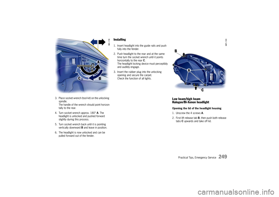
3. Place socket wrench (tool kit) on the unlocking spindle.
The handle of the wrench should point horizon-
tally to the rear.
4. Turn socket wrench approx. 180° A. The
headlight is unlocked and pushed forward
slightly during this process.
5. Turn socket wrench ba ck until it is pointing
vertically downward B and leave in position.
6. The headlight is now unlocked and can be pulled forward out of the fender.
Installing1. Insert headlight into the guide rails and push
fully into the fender.
2. Push headlight to the rear and at the same time turn the socket wrench until it points
horizontally to the rear C.
The headlight locking device must perceptibly
and audibly engage.
3. Insert the rubber plug into the unlocking opening and secure the carpet.
Check the function of all lights.
Low beam/high beam
Halogen/Bi-Xenon headlightOpening the lid of the headlight housing
1. Unscrew the 4 screws A .
2. First lift release tab B, then push both release
tabs C upwards and take off lid.
Page 252 of 284
250
Practical Tips, Emergency Service
Changing bulb for low beam
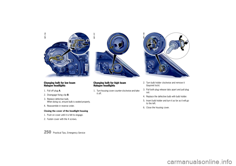
Halogen headlights1. Pull off plug A.
2. Disengage fixing clip B.
3. Replace defective bulb. When doing so, ensure bulb is seated properly.
4. Reassemble in reverse order.
Closing the cover of the headlight housing
1. Push on cover until it is felt to engage.
2. Fasten cover with the 4 screws.
Changing bulb for high beam
Halogen headlights1. Turn housing cover counter-clockwise and take it off. 2. Turn bulb holder clockwise and remove it
(bayonet lock).
3. Pull both plug release tabs apart and pull plug out.
4. Replace the defective bulb with bulb holder.
5. Insert bulb holder and turn it as far as it will go to the left.
6. Close the housing cover.
Page 253 of 284
Practical Tips, Emergency Service
251
Changing bulb for low beam/high beam
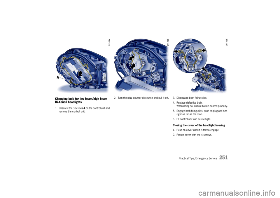
Bi-Xenon headlights1. Unscrew the 3 screws A on the control unit and
remove the control unit. 2. Turn the plug counter-clockwise and pu
ll it off. 3. Disengage both fixing clips.
4. Replace defective bulb.When doing so, ensure bulb is seated properly.
5. Engage both fixing clips, push on plug and turn right as far as the stop.
6. Fit control unit and screw tight.
Closing the cover of the headlight housing
1. Push on cover until it is felt to engage.
2. Fasten cover with the 4 screws.
Page 254 of 284
252
Practical Tips, Emergency Service
Changing bulb for additional high beam
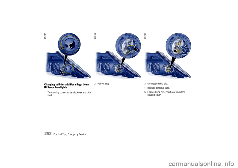
Bi-Xenon headlights1. Turn housing cover counter-clockwise and take it off. 2. Pull off plug. 3. Disengage fixing clip.
4. Replace defective bulb.
5. Engage fixing clip, insert plug and close housing cover.
Page 255 of 284
Practical Tips, Emergency Service
253
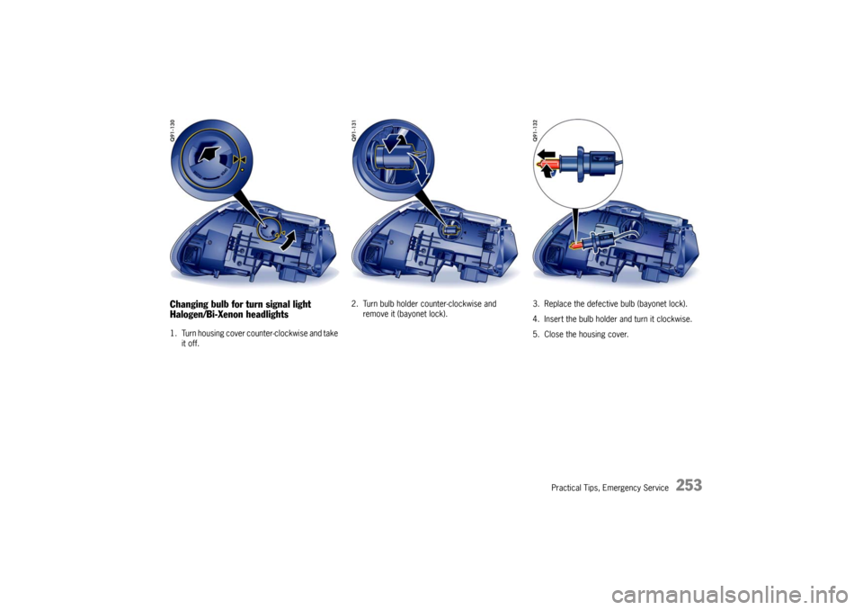
Changing bulb for turn signal light
Halogen/Bi-Xenon headlights1. Turn housing cover counter-clockwise and take it off. 2. Turn bulb holder counter-clockwise and
remove it (bayonet lock). 3. Replace the defective bulb (bayonet lock).
4. Insert the bulb holder and turn it clockwise.
5. Close the housing cover.
Page 256 of 284
254
Practical Tips, Emergency Service
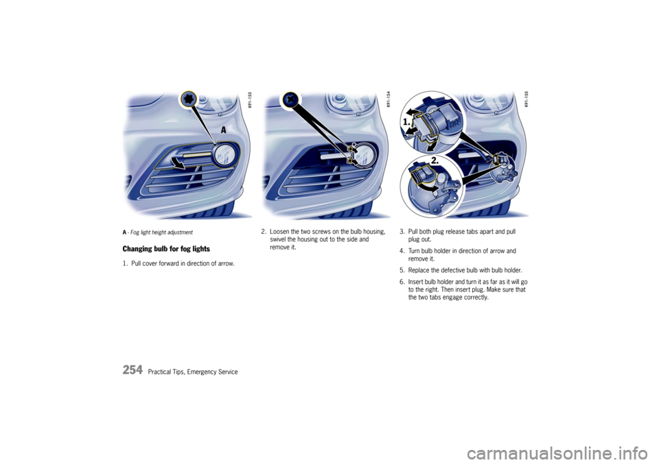
A- Fog light height adjustmentChanging bulb for fog lights1. Pull cover forward in direction of arrow. 2. Loosen the two screws on the bulb housing,
swivel the housing out to the side and
remove it. 3. Pull both plug release tabs apart and pull
plug out.
4. Turn bulb holder in direction of arrow and remove it.
5. Replace the defective bulb with bulb holder.
6. Insert bulb holder and turn it as far as it will go to the right. Then insert plug. Make sure that
the two tabs engage correctly.
Page 257 of 284
Practical Tips, Emergency Service
255
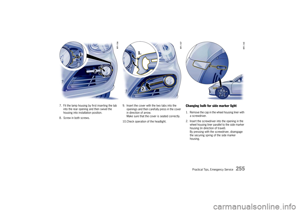
7. Fit the lamp housing by first inserting the tab into the rear opening and then swivel the
housing into installation position.
8. Screw in both screws. 9. Insert the cover with
the two tabs into the
openings and then carefully press in the cover
in direction of arrow.
Make sure that the cover is seated correctly.
10.Check operation of the headlight.
Changing bulb for side marker light1. Remove the cap in the wheel housing liner with a screwdriver.
2. Insert the screwdriver into the opening in the
wheel housing liner parall el to the side marker
housing (in direction of travel).
By pressing with the screwdriver, disengage
the securing spring of the side marker
housing.
Page 258 of 284
256
Practical Tips, Emergency Service
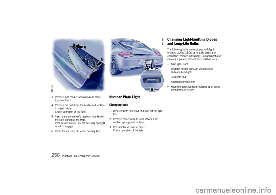
3. Remove side marker and undo bulb holder
(bayonet lock).
4. Remove the bulb from the holder and replace it. Insert holder.
Check operation of the light.
5. Insert the side marker’s retaining lugs A into
the side section at the front.
Push in side marker until the securing spring B
is felt to engage.
6. Press the cap into the wheel housing liner.
Number Plate LightChanging bulb1. Unscrew both screws A and take off the light
lens.
2. Remove defective bulb from between the contact springs and replace.
3. Reassemble in reverse order. Check operation of the light.
Changing Light-Emitting Diodes
and Long-Life BulbsThe following lights are equipped with light-
emitting diodes (LEDs) or long-life bulbs and
cannot be replaced individually. Replacement also
involves a greater amount of installation work.
– Side light, front,
– Daytime driving lights on vehicles with Bi-Xenon headlights,
– Tail lights and
– Additional brake lights
f Have the defective light replaced at an autho-
rized Porsche dealer.
Page 259 of 284

Practical Tips, Emergency Service
257
Adjusting HeadlightsfPlease see the chapter “LIGHTS, REPLACING
BULBS” on Page 247.
Adjustment
The adjustment is made wi th the vehicle ready to
drive and the fuel tank completely filled.
The driver’s seat must be loaded by a person or a
165 lbs. (75 kg) weight and the tire pressures
must meet the prescribed values.
After being loaded, the car must be rolled a few
meters so that the suspension can settle.
For checking the headlight adjustment, the verti-
cal position of the cutoff of the lowbeam (see fig.)
has to be projected on a ve rtical screen (wall) in
distance of 24.6 ft. (7.5 m) from the front lens of
the headlamp.
The correct position of the cutoff is 2.0 in. (5 cm)
at 24.6 ft. or 7.5 m (0.4 °) below a horizontal line,
x cm from ground to the center of the headlamp
lens. Lateral adjustment of the
headlights should be
carried out at a specialist workshop with an optical
adjustment unit.
Distance
Visual aim shall be perf ormed at not less than
24.6 ft./7.5 m (this value is a rounded down con-
version from the 25-foot distance typical of field
aim using a screen). The 24.6 ft./7.5 m distance
is measured from the headlamp lens to the view-
ing screen.
Page 260 of 284

258
Practical Tips, Emergency Service
Floor
The surface upon which the
vehicle rests is flat
and approximately level.
Screen
The screen upon which headlamp beams are pro-
jected is perpendicular to the floor and the vehi-
cle’s longitudinal axis, flat, uniformly light in color,
unobstructed, and wide and high enough to ac-
commodate the vehicle beam patterns to be
aimed.
The screen should be wide enough to provide at
least 3.3 ft. (1 m) of space outboard of the vehi-
cle’s headlamp spacing.
Adjustment screws
fDetach side carpeting in luggage compart-
ment.
Unscrew plastic nut A.
Open the cover of the appropriate adjustment
screw.
The setting is adjusted by turning the hexagon
socket screws right or left, as appropriate.
B - Headlight vertical adjustmentVertical adjustment (screw B)
f turn clockwise = beam moves down
turn counter-clockwise = beam moves up
Note
f Do not alter the lateral adjustment.