alternator PORSCHE PANAMERA 2010 1.G Owners Manual
[x] Cancel search | Manufacturer: PORSCHE, Model Year: 2010, Model line: PANAMERA, Model: PORSCHE PANAMERA 2010 1.GPages: 343, PDF Size: 7.96 MB
Page 9 of 343
Contents
7
Contents
Overview Illustrations......................... 10Driver’s Cockpit ...............................
............. 11
Steering Wheel and Inst rument Panel .............. 12
Dashboard .......................................... ......... 13
Front Center Console . ................................... 14
Overhead Operating Co nsole ......................... 15
Rear ............................................................ 16Opening and Locking ......................... 17Never invite car theft! . ................................... 18
Notes on the Key and Central Locking
System ......................... .............................. 19
Central Locking System ................................ 20
Brief Overview – Opening and Locking
From Outside................................... ............. 21
Opening and Locking From Outside ................ 22
Opening and Locking From Inside................... 31
Opening and Closing the Engine
Compartment Lid ........ .................................. 33
Malfunctions When Open ing and Closing ......... 35Seats, Mirrors and Steering Wheel ..... 37Seat Adjustment and Head Restraints ............. 38
Adjusting Front Seats . ................................... 39
Storing Vehicle Settin gs ................................ 40
Easy Entry Function .... .................................. 42
Adjusting Rear Seats ..................................... 42
Adjusting Passenger Seat From Rear.............. 43
Front and Rear Heated Seats ......................... 43
Front and Rear Seat Ventilation ...................... 44 Safety Belts..............
.................................... 44
Air bag Systems ....... .................................... 47
Child Restraint System s................................. 52
LATCH Child Seat Syst em.............................. 56
Exterior Mirrors ........ .................................... 58
Steering Wheel ......... .................................... 61
Heated steering whee l ................................... 61
Steering Wheel Adjust ment ............................ 62
Multi-Function Steering Wheel......................... 63
Sun Visors .................... ................................ 64
Vanity Mirror ............. .................................... 64
Roll-Up Sunblinds, Rear Side Windows ............ 65
Roll-Up Sunblind, Rear Window ....................... 66
Air Conditioning .... ............................ 67Brief Overview – Front Control Panel ........ 68
Brief Overview – Rear Control Panel
(4-Zone Air-Conditioning) ................................ 69
Overview of Air Conditioning .......................... 70
General Functions ..... .................................... 71
Automatically Controlled Air Conditioning ........ 76
Air Vents ........................................... ........... 82
Heated Rear Window/Exterior Mirror
Heating ............................................. ........... 84Windows and Slide/Tilt Roof............... 85Power Windows ............................................ 86
Slide/Tilt Roof........... .................................... 88
Lights, Turn Signals and
Windshield Wipers. ............................ 91Automatic Driving Light Assistant/
Adaptive Light System ................................... 92
Instrument lighting ....... ................................. 95
Turn Signal/High Beam/Headlight
Flasher Stalk........... ...................................... 96
Emergency Flasher ...... ................................. 97
Interior Lighting............................ ................. 98
Brief Overview – Windshield Wipers ............ 101
Windshield Wiper/Washer Stalk .................... 102Instrument Panel and
Multi-Function Display ..................... 105Instrument Panel USA Mo dels ...................... 107
Instrument Panel Canada Models.................. 109
Tachometer ..................... ........................... 110
Speedometer .................. ........................... 110
Multi-Function Display .................................. 110
Engine Oil Temperature Gauge ..................... 110
Coolant Temperature Gauge ........................ 110
Engine Oil Pressure Ga uge .......................... 111
Fuel Gauge .................. ............................... 111
Digital Speedometer .... ............................... 112
Upshift Prompt Indicato r .............................. 112
Odometer........................ ........................... 112
Reset Button for Trip Counter Display/
Brightness Setting for In strument Lighting.... 112
PDK Display for Selector-Lever Position/
Engaged Gear ................. ........................... 112
Battery/Alternator ........ ............................... 113
Page 107 of 343
Instrument Panel and Multi-Function Display
105
Instrument Panel and Multi-Function Display
Instrument Panel USA
Models...................... 107
Instrument Panel Canada Models ................. 109
Tachometer ................. .............................. 110
Speedometer ............... .............................. 110
Multi-Function Displa y ................................. 110
Engine Oil Temperatur e Gauge .................... 110
Coolant Temperature Gauge ....................... 110
Engine Oil Pressure Gauge.......................... 111
Fuel Gauge .................. .............................. 111
Digital Speedometer ................................... 112
Upshift Prompt Indica tor ............................. 112
Odometer .................... .............................. 112
Reset Button for Trip Counter Display/
Brightness Setting for Instrument Lighting ... 112
PDK Display for Selector-Lever Position/
Engaged Gear.............. .............................. 112
Battery/Alternator ... ................................... 113
Check Engine (Emission Control) ................. 114
Acoustic Signals ..... ................................... 114
Operating the Multi-Function Display in the
Instrument Panel .......... .............................. 115
Vehicle Settings on the Multi-Function
Display ............................................ .......... 138
Overview of Warning Messages ................... 152
Page 115 of 343
Instrument Panel and Multi-Function Display
113
Warning messagesIf the selector lever is between two positions
–Effects: The corresponding selector-lever position in
the instrument panel flashes and the warning
“Gear selector not engaged” appears on the
multi-function display.
Action required:
Operate the footbrake and engage the
selector lever properly.
If there is a fault in the transmission
– Depending on priority, either the warning “Fault Transmission” will appear in yellow or red or
the warning “Gearbox temperature too high”
will appear on the multi-function display.
Ye l l o w “Fault Transmission” warning
–Effects: Restricted gearshift comfort,
reverse gear fails.
Action required:
Have the fault corrected immediately.
Please contact a qualified specialist workshop.
We recommend that you have an authorized
Porsche dealer to do this work as they have
trained workshop personnel and the necessary
parts and tools. Red
“Fault Transmission” warning
–Effect: Vehicle can be driven only until it comes to
astop.
Action required:
It is not possible to continue driving.
Stop the vehicle immediately in a suitable
place. Have the vehicle towed to a qualified
specialist workshop.
Warning “Gearbox temperature too high”
–Effects: “Warning jerks” can be felt when driving off
and the engine power may be restricted.
Action required:
Do not hold the vehicle with the accelerator on
a hill, for example. Hold the vehicle with the
brake. Reduce engine load. Stop the vehicle in
a suitable place if possible. Allow the engine to
run in selector-lever position P or N until the
warning disappears.
f Please see the chapter “REDUCED DRIVING
PROGRAM” on page 199.
f Please see the chapter “PORSCHE
DOPPELKUPPLUNG (PDK)” on page 193.
Battery/AlternatorThe warning message “Fault Generator” will
appear on the multi-function display in the
instrument panel if the ve hicle electrical system
voltage drops significantly.
f Stop at a safe place and switch the engine off.
For information on warning messages on the
multi-function display:
f Please see the chapter “OVERVIEW OF
WARNING MESSAGES” on page 152.Possible causes– Defect in the battery charging system
– Broken drive belt
Warning message
Page 272 of 343
270
Maintenance and Car Care
High-pressure cleaning equipment
Warning!
High-pressure cleaning equipment can
damage the following components:
–Tires
– Logos, emblems, decorative foils
– Painted surfaces
– Alternator, valve covers
– ParkAssist sensors
– Radar sensor for adaptive cruise control
– Rearview camera
f Always read the operating instructions
provided by the equipment manufacturer.
f Always cover the lid of the brake fluid reservoir
prior to cleaning. Never point the cleaning jet
directly at the lid.
f When cleaning with a flat-jet nozzle or
a so-called “dirt blaster”. maintain a minimum
distance of 20 in. (50 cm).
f Never use high-pressure cleaning equipment
with a round-jet nozzle.
A high-pressure cleaning device fitted with
a round nozzle will damage your vehicle. The
tires are particularly susceptible to damage.
f Do not point the cleaning jet directly at any of the aforementioned components.
Decorative film
Caution!
Risk of damage due to separation of the
decorative film when using high-pressure
cleaning equipment.
f When cleaning components, the water must
not be hotter than 140 °F (60 °C) and the
pressure no greater than 580 psi (40 bar).
Always observe a minimum distance of 20 in. (50 cm).
Care of door lockfTo prevent the door lock from freezing
during the cold season, cover the lock barrel
with suitable adhesive tape while washing
the vehicle.
If the lock still freezes, use an ordinary de-icer.
In many cases, a well warmed key can help.
Never use excessive force.
Car washingThe best protection for the vehicle from the
damaging effects of the environment is frequent
washing and preservation.
The longer road salt, road dust, industrial dust,
insect remains, bird excrement, and tree sap,
resin, pollen, etc. are allowed to remain on the
bodywork, the more harmful their effect.
Observe the following poi nts in order to ensure
that the vehicle is washed thoroughly without
damaging the paintwork:
f The underside of the vehicle should also be
thoroughly washed at the end of the winter
season at the latest.
f Wash your vehicle only at sites provided for
this purpose to prevent soot, grease, oil and
heavy metals from entering the environment.
f Dark colors are slightly more susceptible
to scratching and require particularly careful
paint care.
Dark paints make even the smallest surface
blemishes (scratches) more conspicuous than
lighter colors.
f Do not wash your Porsche in direct sunlight
or when its body is hot.
f When washing by hand, use a car shampoo,
plenty of water, and a soft sponge or washing
brush.
We recommend Porsche car shampoo.
Page 274 of 343

272
Maintenance and Car Care
Polishing
Only when the original
shine can no longer be
obtained using preservatives should paint polish
be used to clean the paint.
We recommend Porsche paint polish.
Removing spots and stains
f Remove tar spatters, traces of oil, insects etc.
as soon as possible using an insect remover,
as they discolor the paint if left to work on it
over time.
f Wash the treated areas carefully afterwards.
Repairing minor paint damage
f Have minor paint damage (cracks, scratches
or stone damage) repaired immediately
before corrosion begins.
Please contact a qualif ied specialist workshop.
We recommend that you have an authorized
Porsche dealer to do this work as they have
trained workshop personnel and the necessary
parts and tools.
If traces of corrosion have already formed, these
must be thoroughly removed. An anti-corrosion
primer must then be applied to these spots,
followed by top-coat paint. Paint data can be found on the vehicle data
carrier.
f
Please see the chapter “VEHICLE DATA BANK”
on page 323.
Cleaning the engine compartment
Caution!
Risk of damage, e.g. to the alternator,
painted surfaces, and the valve covers.
f Never use high-pressure cleaners with
a round-jet nozzle.
f Always observe a minimum distance of 20 in.
(50 cm).
f Always cover the lid of the brake fluid reservoir
prior to cleaning with a high-pressure cleaner.
Never point the cleaning jet directly at the lid.
f Do not point the cleaning jet directly at any of the aforementioned components.
Note on operation
If the vehicle is driven frequently on salted
or gritted roads:
f Have the engine compartment cleaned
regularly.
Cleaning windowsfClean all windows regularly, inside and out,
with window cleaner.
We recommend Porsche window cleaner.
f Do not use the same chamois for painted
surfaces and for drying the windows.
Preservative residues could reduce
transparency.
f Remove insect residues with insect remover.
Note
The front side windows have a water-repellent
(hydrophobic) coating, which prevents soiling
of the windows.
This coating is subject to natural wear and can
be renewed.
f Please contact a qualified specialist workshop.
We recommend that you have an authorized
Porsche dealer to do this work as they have
trained workshop personnel and the necessary
parts and tools.
Page 308 of 343
306
Minor Repairs
External Power Supply,
Jump-Lead StartingIf the battery is flat, the battery of another vehicle
can be used for starting or as an external power
supply with the help of jump leads.
Both batteries must be 12 V batteries.
The capacity (Ah) of the do nor battery must not be
substantially less than that of the flat battery.
The flat battery must be connected correctly to
the vehicle’s electrical system.
Warning!
Risk of short circuit, damage and explosion,
resulting in serious personal injury or death.
f Use only jumper cables of adequate diameter
cross-section and fitted with completely
insulated alligator clips.
f Follow all warnings and instructions of the
jumper cable manufacturer.
f When connecting jumper cables, make sure
that they cannot get ca ught in any moving
parts in the engine compartment.
The jumper cables must be long enough so
that neither vehicles nor cables touch another.
f The vehicles must not be in contact, otherwise
current might flow as soon as the positive
terminals are connected.
f The cable clamps must not be allowed to
contact each other when one end of the
jumper cables are connected to a battery. f
Carefully ensure that tools or conductive
jewelery (rings, chains, watch straps) do not
come into contact with the positive jumper
cable or the positive battery post.
f Improper hook-up of jumper cables can ruin
the alternator.
Danger of caustic burns.
f Do not lean over the battery.
Danger of gas explosion.
f Improper use of booster battery to start a
vehicle may cause an explosion, resulting in
serious personal injury or death.
f Keep sources of ignition away from the
battery, e.g. open flame, burning cigarettes or
sparking due to cable contact or welding work.
f A discharged battery can freeze even at
14 °F ( −10 °C). Before connecting jumper
cables, a frozen battery must be thawed out.
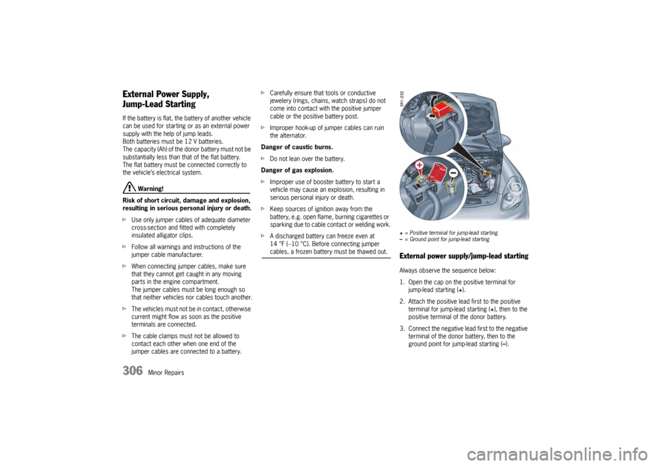
+ = Positive terminal for jump-lead starting
– = Ground point for jump-lead startingExternal power supply/jump-lead startingAlways observe the sequence below:
1. Open the cap on the positive terminal for
jump-lead starting ( +).
2. Attach the positive lead first to the positive terminal for jump-lead starting ( +), then to the
positive terminal of the donor battery.
3. Connect the negative lead first to the negative
terminal of the donor battery, then to the
ground point for jump-lead starting ( –).