service indicator Ram 1500 2015 User Guide
[x] Cancel search | Manufacturer: RAM, Model Year: 2015, Model line: 1500, Model: Ram 1500 2015Pages: 871, PDF Size: 24.83 MB
Page 479 of 871

direct gears only. Normal operation will resume once the
transmission temperature has risen to a suitable level.
Transmission Limp Home Mode
Transmission function is monitored electronically for
abnormal conditions. If a condition is detected that could
result in transmission damage, Transmission Limp Home
Mode is activated. In this mode, the transmission remains
in direct gear regardless of which forward gear is se-
lected. PARK, REVERSE, and NEUTRAL will continue to
operate. The Malfunction Indicator Light (MIL) may be
illuminated. Limp Home Mode allows the vehicle to be
driven to an authorized dealer for service without dam-
aging the transmission.
In the event of a momentary problem, the transmission
can be reset to regain all forward gears by performing the
following steps:
1. Stop the vehicle.
2. Shift the transmission into PARK.
3. Turn the ignition switch to the OFF position.
4. Wait approximately 10 seconds.
5. Restart the engine.
6. Shift into the desired gear range. If the problem is no
longer detected, the transmission will return to normal
operation.
NOTE:Even if the transmission can be reset, we recom-
mend that you visit your authorized dealer at your
earliest possible convenience. Your authorized dealer has
diagnostic equipment to determine if the problem could
recur.
If the transmission cannot be reset, authorized dealer
service is required.
5
STARTING AND OPERATING 477
Page 491 of 871

During cold temperatures, transmission operation may
be modified depending on engine and transmission
temperature as well as vehicle speed. This feature im-
proves warm up time of the engine and transmission to
achieve maximum efficiency. Engagement of both the
torque converter clutch and the top overdrive gear are
inhibited until the transmission fluid is warm (refer to the
“Note” under “Torque Converter Clutch” in this section).
During extremely cold temperatures (-16°F [-27°C] or
below), operation may briefly be limited to first and
direct gears only. Normal operation will resume once the
transmission temperature has risen to a suitable level.
Transmission Limp Home Mode
Transmission function is monitored electronically for ab-
normal conditions. If a condition is detected that could
result in transmission damage, Transmission Limp Home
Mode is activated. In this mode, the transmission remains
in fourth gear regardless of which forward gear is selected.
PARK, REVERSE, and NEUTRAL will continue to operate.
The Malfunction Indicator Light (MIL) may be illuminated.
Limp Home Mode allows the vehicle to be driven to an
authorized dealer for service without damaging the trans-
mission.
In the event of a momentary problem, the transmission
can be reset to regain all forward gears by performing the
following steps:
1. Stop the vehicle.
2. Shift the transmission into PARK.
3. Turn the ignition switch to the OFF position.
4. Wait approximately 10 seconds.
5. Restart the engine.
6. Shift into the desired gear range. If the problem is no
longer detected, the transmission will return to normal
operation.
5
STARTING AND OPERATING 489
Page 508 of 871

Transfer Case Position Indicator Lights
The Transfer Case Position Indicator Lights (4WD,
4LOW, and 4WD AUTO) are located in the instrument
cluster and indicate the current and desired transfer case
selection. When you select a different transfer case posi-
tion, the indicator lights will do the following:
If All Shift Conditions Are Met:
1. The current position indicator light will turn OFF.
2. The selected position indicator light will flash until the
transfer case completes the shift.
3. When the shift is complete, the indicator light for the
selected position will stop flashing and remain ON.
If One Or More Shift Conditions Are Not Met:
1. The indicator light for the current position will remain
ON.
2. The newly selected position indicator light will con-
tinue to flash.
3. The transfer casewill notshift.
NOTE:Before retrying a selection, make certain that all
the necessary requirements for selecting a new transfer
case position have been met. To retry the selection, turn
the control knob back to the current position, wait five
seconds, and retry selection. To find the shift require-
ments, refer to the#Shifting Procedure#for your transfer
case, located in this section.
The “SVC 4WD Warning Light” monitors the electronic
shift four-wheel drive system. If this light remains on
after engine start up or illuminates during driving, it
means that the four-wheel drive system is not function-
ing properly and that service is required.
506 STARTING AND OPERATING
Page 620 of 871

These indicators are molded into the bottom of the tread
grooves. They will appear as bands when the tread depth
becomes a 1/16 of an inch (2 mm). When the tread is
worn to the tread wear indicators, the tire should be
replaced. Refer to “Replacement Tires” in this section for
further information.
Life Of Tire
The service life of a tire is dependent upon varying
factors including, but not limited to:
•Driving style.
•Tire pressure - Improper cold tire inflation pressures
can cause uneven wear patterns to develop across the
tire tread. These abnormal wear patterns will reduce
tread life, resulting in the need for earlier tire replace-
ment.
•Distance driven.
•Performance tires, tires with a speed rating of V or
higher, and summer tires typically have a reduced
tread life. Rotation of these tires per the vehicle main-
tenance schedule is highly recommended.
WARNING!
Tires and the spare tire should be replaced after six
years, regardless of the remaining tread. Failure to
follow this warning can result in sudden tire failure.
You could lose control and have a collision resulting
in serious injury or death.
Keep dismounted tires in a cool, dry place with as little
exposure to light as possible. Protect tires from contact
with oil, grease, and gasoline.
618 STARTING AND OPERATING
Page 753 of 871

ONBOARD DIAGNOSTIC SYSTEM (OBD II)
Your vehicle is equipped with a sophisticated onboard
diagnostic system called OBD II. This system monitors
the performance of the emissions, engine, and automatic
transmission control systems. When these systems are
operating properly, your vehicle will provide excellent
performance and fuel economy, as well as engine emis-
sions well within current government regulations.
If any of these systems require service, the OBD II system
will turn on the “Malfunction Indicator Light (MIL).” It
will also store diagnostic codes and other information to
assist your service technician in making repairs. Al-
though your vehicle will usually be drivable and not
need towing, see your authorized dealer for service as
soon as possible.
CAUTION!
•Prolonged driving with the MIL on could cause
further damage to the emission control system. It
could also affect fuel economy and driveability.
The vehicle must be serviced before any emissions
tests can be performed.
•If the MIL is flashing, while the engine is running,
severe catalytic converter damage and power loss
will soon occur. Immediate service is required.
Loose Fuel Filler Cap Message
If the vehicle diagnostic system determines
that the fuel filler cap is loose, improperly
installed, or damaged, a loose gascap indicator
will display in the EVIC/DID telltale display
area. Refer to “Electronic Vehicle Information Center
7
MAINTAINING YOUR VEHICLE 751
Page 754 of 871

(EVIC)” or “Driver Information Display (DID)” in “Un-
derstanding Your Instrument Panel” for further informa-
tion. Tighten the fuel filler cap properly and press the
SELECT button to turn off the message. If the problem
continues, the message will appear the next time the
vehicle is started.
A loose, improperly installed, or damaged fuel filler cap
may also turn on the Malfunction Indicator Light (MIL).
EMISSIONS INSPECTION AND MAINTENANCE
PROGRAMS
In some localities, it may be a legal requirement to pass
an inspection of your vehicle’s emissions control system.
Failure to pass could prevent vehicle registration.
For states that require an Inspection and Mainte-
nance (I/M), this check verifies the “Malfunction
Indicator Light (MIL)” is functioning and is not
on when the engine is running, and that the OBD II
system is ready for testing.
Normally, the OBD II system will be ready. The OBD II
system maynotbe ready if your vehicle was recently
serviced, recently had a dead battery or a battery replace-
ment. If the OBD II system should be determined not
ready for the I/M test, your vehicle may fail the test.
Your vehicle has a simple ignition actuated test, which
you can use prior to going to the test station. To check if
your vehicle’s OBD II system is ready, you must do the
following:
1. Cycle the ignition switch to the ON position, but do
not crank or start the engine.
NOTE:If you crank or start the engine, you will have to
start this test over.
2. As soon as you cycle the ignition switch to the ON
position, you will see the MIL symbol come on as part
of a normal bulb check.
752 MAINTAINING YOUR VEHICLE
Page 830 of 871

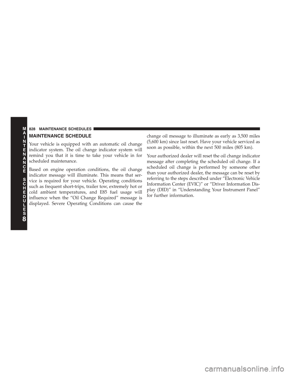
MAINTENANCE SCHEDULE
Your vehicle is equipped with an automatic oil change
indicator system. The oil change indicator system will
remind you that it is time to take your vehicle in for
scheduled maintenance.
Based on engine operation conditions, the oil change
indicator message will illuminate. This means that ser-
vice is required for your vehicle. Operating conditions
such as frequent short-trips, trailer tow, extremely hot or
cold ambient temperatures, and E85 fuel usage will
influence when the “Oil Change Required” message is
displayed. Severe Operating Conditions can cause the
change oil message to illuminate as early as 3,500 miles
(5,600 km) since last reset. Have your vehicle serviced as
soon as possible, within the next 500 miles (805 km).
Your authorized dealer will reset the oil change indicator
message after completing the scheduled oil change. If a
scheduled oil change is performed by someone other
than your authorized dealer, the message can be reset by
referring to the steps described under “Electronic Vehicle
Information Center (EVIC)” or “Driver Information Dis-
play (DID)” in “Understanding Your Instrument Panel”
for further information.
8
MAINTENANCE
SCHEDULES
828 MAINTENANCE SCHEDULES
Page 859 of 871

Lead Free Gasoline........................634
Leaks, Fluid.............................118
Life of Tires.............................618
Light Bulbs..............................118
Lights.................................118
Airbag................................79
Alarm...............................294
Anti-Lock.............................289
Anti-Lock Warning......................583
Automatic Headlights....................167
Brake Assist Warning....................591
Brake Warning.........................291
Bulb Replacement.......................809
Cap Top Clearance......................816
Cargo . . . . . . . . . . . . . . . . . . . . . . . . . . . . . ..176
Center Mounted Stop....................814
Check Engine (Malfunction Indicator).........289
Courtesy/Reading......................174
Daytime Running.......................168
Electronic Stability Program (ESP) Indicator.....591
Exterior..............................118
Fog . . . . . . . . . . . . . . . . . . . . . . . . . . . . . . . ..171
Four-Wheel Drive Indicator................497
Hazard Warning Flasher..................685
Headlights............................166
High Beam............................178
High Beam Indicator.....................293
High Beam/Low Beam Select...............178
Hill Descent Control Indicator..............593
Illuminated Entry........................23
Instrument Cluster......................289
Interior..............................172
Oil Pressure...........................294
Passing..............................177
Seat Belt Reminder......................293
Security Alarm.........................294
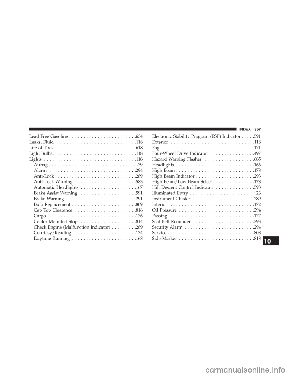
Service...............................808
SideMarker...........................81810
INDEX 857
Page 860 of 871

Tire Pressure Monitoring (TPMS)............294
Traction Control........................591
Transfer Case..........................497
Turn Signal............................118
Warning (Instrument Cluster Description)......289
Limited-Slip Differential....................551
Loading Vehicle..........................646
Ti re s . . . . . . . . . . . . . . . . . . . . . . . . . . . . . . ..603
Locks..................................37
Automatic Door.........................40
Child Protection.........................41
Door.................................37
Power Door............................39
Low Tire Pressure System...................626
Lubrication, Body.........................767
Lug Nuts...............................686
Maintenance Free Battery....................764
Maintenance Procedures....................754
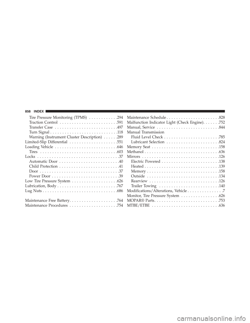
Maintenance Schedule......................828
Malfunction Indicator Light (Check Engine).......752
Manual, Service..........................844
Manual Transmission
Fluid Level Check.......................785
Lubricant Selection......................824
Memory Seat............................158
Methanol...............................636
Mirrors................................126
Electric Powered........................138
Heated...............................139
Memory..............................158
Outside..............................134
Rearview.............................126
Trailer Towing.........................140
Modifications/Alterations, Vehicle...............7
Monitor, Tire Pressure System................626
MOPAR® Parts...........................753
MTBE/ETBE............................636
858 INDEX
Page 867 of 871

Disabled Vehicle........................740
Guide...............................657
Recreational...........................673
Weight...............................657
Towing Vehicle Behind a Motorhome...........673
Traction................................551
Traction Control..........................583
Trailer Sway Control (TSC)..................592
Trailer Towing...........................648
Cooling System Tips.....................668
Hitches..............................656
Minimum Requirements..................658
Mirrors..............................140
Trailer and Tongue Weight.................657
Wiring...............................666
Trailer Towing Guide.......................657
Trailer Weight............................657
Transfer Case............................785
Electronically Shifted.....................498
Fluid................................824
Transmission............................461
Automatic............................461
Fluid................................824
Maintenance...........................786
Shifting..............................459
Transmitter Battery Service (Remote Keyless Entry). . .30
Transmitter Programming (Remote Keyless Entry) . . .24
Transmitter, Remote Keyless Entry (RKE).........24
Tread Wear Indicators......................617
Turn Signals.............................176
Uconnect®
Customer Programmable Features...........367
Operation.............................394
Uconnect® Settings......................356
Uconnect® Settings......................367
Uconnect® Settings
Customer Programmable Features............4210
INDEX 865