key Ram 1500 2015 Workshop Manual
[x] Cancel search | Manufacturer: RAM, Model Year: 2015, Model line: 1500, Model: Ram 1500 2015Pages: 871, PDF Size: 24.83 MB
Page 229 of 871
Sunroof Maintenance
Use only a nonabrasive cleaner and a soft cloth to clean
the glass panel.
Ignition Off Operation
The power sunroof switch will remain active for up to
approximately ten minutes after the ignition switch is
turned to the LOCK position. Opening either front door
will cancel this feature.
NOTE:Ignition Off time is programmable through the
Uconnect® System. Refer to “Uconnect® Settings/
Customer Programmable Features” in “Understanding
Your Instrument Panel” for further information.
ELECTRICAL POWER OUTLETS
The auxiliary 12 Volt (13 Amp) power outlets can provide
power for in-cab accessories designed for use with the
standard “cigar lighter” plug. The 12 Volt power outlets
have a cap attached to the outlet indicating “12V DC,”
together with either a key symbol or a battery symbol.
A key symbol indicates that the key must be in the
ON/RUN or ACC positions for the outlet to provide
power. The battery symbol indicates that the outlet is
connected to the battery, and can provide power at all
times.
NOTE:To ensure proper operation, a MOPAR® knob
and element must be used.
3
UNDERSTANDING THE FEATURES OF YOUR VEHICLE 227
Page 233 of 871
The key symbol indicates that this outlet can supply
power when the key is in the ON/RUN or ACC posi-
tions.
All accessories connected to the outlet(s) should be
removed or turned off when the vehicle is not in use to
protect the battery against discharge.
WARNING!
To avoid serious injury or death:
•Only devices designed for use in this type of outlet
should be inserted into any 12 Volt outlet.
•Do not touch with wet hands.
•Close the lid when not in use and while driving the
vehicle.
•If this outlet is mishandled, it may cause an electric
shock and failure.
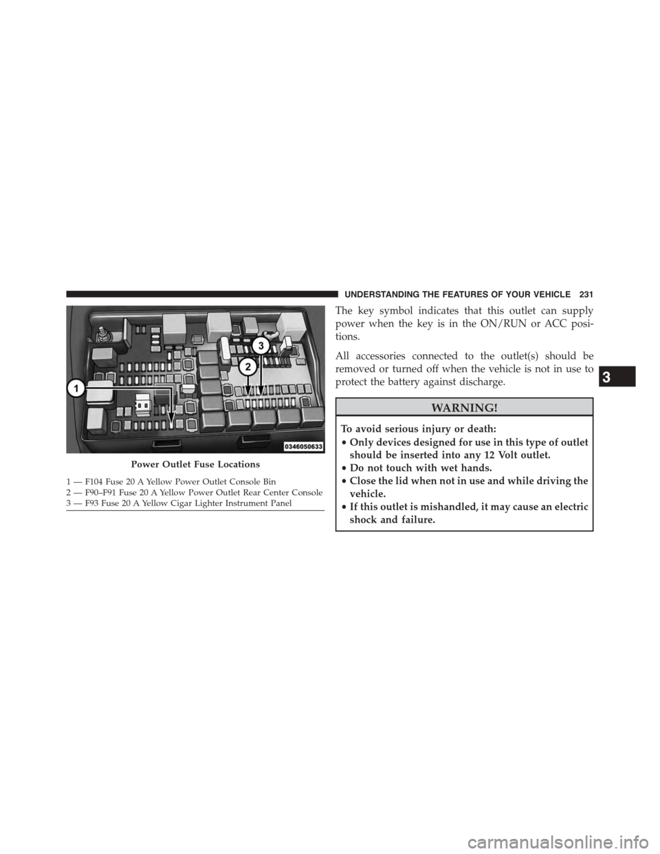
Power Outlet Fuse Locations
1—F104Fuse20AYellowPowerOutletConsoleBin2 — F90–F91 Fuse 20 A Yellow Power Outlet Rear Center Console3—F93Fuse20AYellowCigarLighterInstrumentPanel
3
UNDERSTANDING THE FEATURES OF YOUR VEHICLE 231
Page 258 of 871
CAUTION!
Leaving the lid open for extended periods of time
could cause the vehicle battery to discharge. If the lid
is required to stay open for extended periods of time,
(Continued)
CAUTION!(Continued)
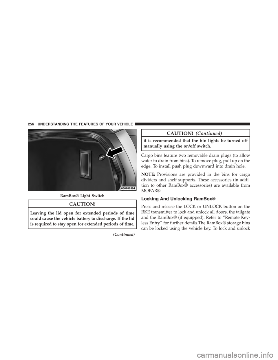
it is recommended that the bin lights be turned off
manually using the on/off switch.
Cargo bins feature two removable drain plugs (to allow
water to drain from bins). To remove plug, pull up on the
edge. To install push plug downward into drain hole.
NOTE:Provisions are provided in the bins for cargo
dividers and shelf supports. These accessories (in addi-
tion to other RamBox® accessories) are available from
MOPAR®.
Locking And Unlocking RamBox®
Press and release the LOCK or UNLOCK button on the
RKE transmitter to lock and unlock all doors, the tailgate
and the RamBox® (if equipped). Refer to “Remote Key-
less Entry” for further details.The RamBox® storage bins
can be locked using the vehicle key. To lock and unlock
RamBox® Light Switch
256 UNDERSTANDING THE FEATURES OF YOUR VEHICLE
Page 259 of 871
the storage bin, insert the key into the keyhole on the
pushbutton and turn clockwise to lock or counterclock-
wise to unlock. Always return the key to the upright
(vertical) position before removing the key from the
pushbutton.
CAUTION!
•Ensure cargo bin lids are closed and latched before
moving or driving vehicle.
•Loads applied to the top of the bin lid should be
minimized to prevent damage to the lid and
latching/hinging mechanisms.
•Damage to the RamBox® bin may occur due to
heavy/sharp objects placed in bin that shift due to
vehicle motion. In order to minimize potential for
damage, secure all cargo to prevent movement and
protect inside surfaces of bin from heavy/sharp
objects with appropriate padding.
RamBox® Safety Warning
Carefully follow these warnings to help prevent personal
injury or damage to your vehicle:
WARNING!
•Always close the storage bin covers when your
vehicle is unattended.
•Do not allow children to have access to the storage
bins. Once in the storage bin, young children may
not be able to escape. If trapped in the storage bin,
children can die from suffocation or heat stroke.
•In an accident, serious injury could result if the
storage bin covers are not properly latched.
•Do not drive the vehicle with the storage bin covers
open.
•Keep the storage bin covers closed and latched
while the vehicle is in motion.
•Do not use a storage bin latch as a tie down.
3
UNDERSTANDING THE FEATURES OF YOUR VEHICLE 257
Page 261 of 871
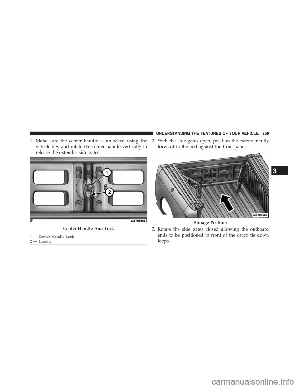
1. Make sure the center handle is unlocked using the
vehicle key and rotate the center handle vertically to
release the extender side gates.
2. With the side gates open, position the extender fully
forward in the bed against the front panel.
3. Rotate the side gates closed allowing the outboard
ends to be positioned in front of the cargo tie down
loops.
Center Handle And Lock
1—CenterHandleLock2—Handle
Storage Position
3
UNDERSTANDING THE FEATURES OF YOUR VEHICLE 259
Page 262 of 871
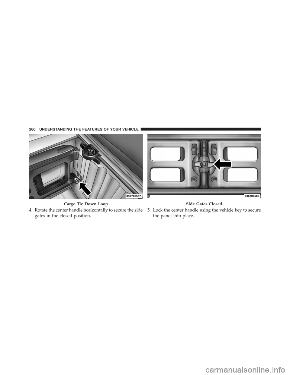
4. Rotate the center handle horizontally to secure the side
gates in the closed position.
5. Lock the center handle using the vehicle key to secure
the panel into place.
Cargo Tie Down LoopSide Gates Closed
260 UNDERSTANDING THE FEATURES OF YOUR VEHICLE
Page 263 of 871
Divider Position
The divider position is intended for managing your cargo
and assisting in keeping cargo from moving around the
bed. There are 11 divider slots along the bed inner panels
which allow for various positions to assist in managing
your cargo.
To install the bed extender into a divider position per-
form the following:
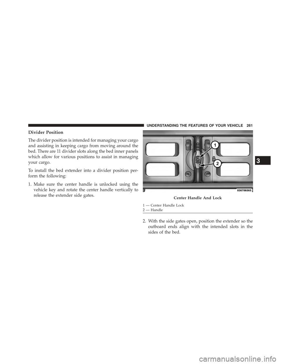
1. Make sure the center handle is unlocked using the
vehicle key and rotate the center handle vertically to
release the extender side gates.
2. With the side gates open, position the extender so the
outboard ends align with the intended slots in the
sides of the bed.
Center Handle And Lock
1—CenterHandleLock2—Handle
3
UNDERSTANDING THE FEATURES OF YOUR VEHICLE 261
Page 271 of 871
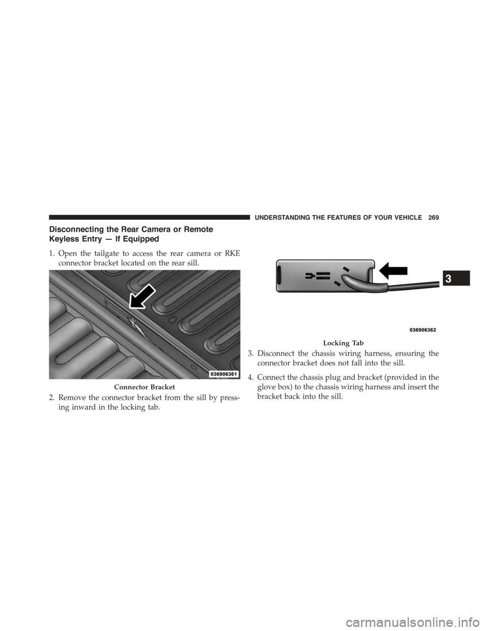
Disconnecting the Rear Camera or Remote
Keyless Entry — If Equipped
1. Open the tailgate to access the rear camera or RKE
connector bracket located on the rear sill.
2. Remove the connector bracket from the sill by press-
ing inward in the locking tab.
3. Disconnect the chassis wiring harness, ensuring the
connector bracket does not fall into the sill.
4. Connect the chassis plug and bracket (provided in the
glove box) to the chassis wiring harness and insert the
bracket back into the sill.
Connector Bracket
Locking Tab
3
UNDERSTANDING THE FEATURES OF YOUR VEHICLE 269
Page 273 of 871
5. Slide the entire tailgate to the right to free the left side
pivot.
6. Remove the tailgate from the vehicle.
NOTE:Do not carry the tailgate loose in the truck
pickup box.
WARNING!
To avoid inhaling carbon monoxide, which is deadly,
the exhaust system on vehicles equipped with “Cap or
Slide-In Campers” should extend beyond the over-
hanging camper compartment and be free of leaks.
Locking Tailgate
The lock is located next to the tailgate handle. The
tailgate can be locked using the vehicle key or by locking
the truck with the key-fob if equipped with remote
keyless entry.
TRI-FOLD TONNEAU COVER — IF EQUIPPED
Your vehicle may be equipped with a Tri-Fold Tonneau
Cover which consists of different features:
•Easy Tri-Fold cover
•Tonneau fore aft locator
•Crosscar inside bed locator
•Front and rear clamps
•Stowage strap
•Locking Capability
NOTE:The Tonneau Cover can be folded up and secured
at the front of the box without removing completely.
3
UNDERSTANDING THE FEATURES OF YOUR VEHICLE 271
Page 301 of 871
WARNING!
A hot engine cooling system is dangerous. You or
others could be badly burned by steam or boiling
coolant. You may want to call an authorized dealer
for service if your vehicle overheats. If you decide to
look under the hood yourself, see “Maintaining Your
Vehicle.” Follow the warnings under the “Cooling
System Pressure Cap” paragraph.
25. Stop/Start – If Equipped
Press and release the UP or DOWN arrow
button until the Stop/Start icon is highlighted
in the EVIC. Press and release the RIGHT
arrow button to display the Stop/Start status.
26.Electric Power Steering Malfunction Warning Light —
If Equipped
This telltale is on when the Electric Power
Steering is not operating and needs service.
27. Electronic Throttle Control (ETC) Light
This light informs you of a problem with the
Electronic Throttle Control (ETC) system. The
light will come on when the ignition is first
turned ON and remain on briefly as a bulb
check. If the light does not come on during starting, have
the system checked by an authorized dealer.
If a problem is detected, the light will come on while the
engine is running. Cycle the ignition key when the
vehicle has completely stopped and the shift lever is
placed in the PARK position. The light should turn off.
4
UNDERSTANDING YOUR INSTRUMENT PANEL 299