indicator lights Ram 1500 2017 Owner's Guide
[x] Cancel search | Manufacturer: RAM, Model Year: 2017, Model line: 1500, Model: Ram 1500 2017Pages: 734, PDF Size: 7.3 MB
Page 434 of 734

3. Push the desired position on the transfer case controlswitch.
4. After the desired position indicator light is ON (not flashing), shift the transmission back into gear.
NOTE:
• If Steps 1 or 2 of either the Preferred or Alternate
Procedure are not satisfied prior to attempting the shift
or if they no longer are being met while the shift attempt
is in process, the desired position indicator light will
flash continuously while the original position indicator
light is ON, until all requirements have been met.
• The ignition switch must be in the ON position for a
shift to take place and for the position indicator lights to
be operable. If the ignition switch is not in the ON
position, then the shift will not take place and no
position indicator lights will be on or flashing.
Five-Position Electronically Shifted Transfer Case
(Eight Speed Transmission Only) — If Equipped
This is an electronic shift transfer case and is operated by
the 4WD Control Switch (Transfer Case Switch), which is
located on the instrument panel. This electronically shifted transfer case provides five mode
positions:
•
Two-Wheel Drive High Range (2WD)
• Four-Wheel Drive Automatic High Range (4WD AUTO)
• Four-Wheel Drive Lock High Range (4WD LOCK)
• Four-Wheel Drive Low Range (4WD LOW)
• Neutral (NEUTRAL)
Five-Position/On-Demand Transfer Case — Eight Speed
Transmission Only
432 STARTING AND OPERATING
Page 436 of 734

When additional traction is required, the transfer case 4WD
LOCK and 4WD LOW positions can be used to maximize
torque to the front driveshaft, forcing the front and rear
wheels to rotate at the same speed. This is accomplished
pushing the desired position on the 4WD Control Switch.
Refer to “Shifting Procedure” in this section for specific
shifting instructions.
The 4WD LOCK and 4WD LOW positions are designed for
loose, slippery road surfaces only. Driving in the 4WD
LOCK and 4WD LOW positions on dry hard surfaced
roads may cause increased tire wear and damage to the
driveline components.
NOTE:The transfer case NEUTRAL button is located in
the center of the 4WD Control Switch and is pushed by
using a ballpoint pen or similar object. The transfer case
NEUTRAL position is to be used for recreational towing
only. Refer to “Recreational Towing” in “Starting And
Operating” for further information.
Transfer Case Position Indicator Lights
The Transfer Case Position Indicator Lights (4WD, 4LOW,
and 4WD AUTO) are located in the instrument cluster and indicate the current and desired transfer case selection.
When you select a different transfer case position, the
indicator lights will do the following:
If All Of The Following Shift Conditions Are Met:
1. The current position indicator light will turn OFF.
2. The selected position indicator light will flash until the
transfer case completes the shift.
3. When the shift is complete, the indicator light for the selected position will stop flashing and remain ON.
If One Or More Of The Following Shift Conditions Are
Not Met:
1. The indicator light for the current position will remain ON.
2. The newly selected position indicator light will continue to flash.
3. The transfer case will notshift.
434 STARTING AND OPERATING
Page 439 of 734

2WD Or 4WD AUTO Or 4WD LOCK To 4WD LOW
NOTE:When shifting into or out of 4WD LOW some gear
noise may be heard. This noise is normal and is not
detrimental to the vehicle or occupants.
Shifting can be performed with the vehicle rolling 2 to
3 mph (3 to 5 km/h) or completely stopped. Use either of
the following procedures:
Preferred Procedure
1. With the engine running, slow the vehicle to 2 to 3 mph (3 to 5 km/h).
2. Shift the transmission into NEUTRAL.
3. While still rolling, push the desired position on the transfer case control switch.
4. After the desired position indicator light is ON (not flashing), shift the transmission back into gear. Alternate Procedure
1. Bring the vehicle to complete stop.
2. With the ignition switch in the ON position and the
engine running, shift the transmission into NEUTRAL.
3. Push the desired position on the transfer case control switch.
4. After the desired position indicator light is ON (not flashing), shift the transmission back into gear.
NOTE:
• If Steps 1 or 2 of either the Preferred or Alternate
Procedure are not satisfied prior to attempting the shift
or if they no longer are being met while the shift attempt
is in process, the desired position indicator light will
flash continuously while the original position indicator
light is ON, until all requirements have been met.
• The ignition switch must be in the ON position for a
shift to take place and for the position indicator lights to
be operable. If the ignition switch is not in the ON
position, then the shift will not take place and no
position indicator lights will be on or flashing.
5
STARTING AND OPERATING 437
Page 578 of 734

12. Turn the ignition to the OFF mode, then cycle theignition to the RUN mode and back to the OFF mode.
Remove the key fob from the ignition.
13. Attach the vehicle to the tow vehicle using a suitable tow bar.
14. Release the parking brake.
NOTE: With electronic shift transfer case:
• Steps 2 through 4 are requirements that must be met
before pushing the NEUTRAL (N) button, and must
continue to be met until the shift has been completed. If
any of these requirements are not met before pushing
the NEUTRAL (N) button or are no longer met during
the shift, the NEUTRAL (N) indicator light will flash
continuously until all requirements are met or until the
NEUTRAL (N) button is released.
• The ignition must be in the ON/RUN mode for a shift to
take place and for the position indicator lights to be
operable. If the ignition is not in the ON/RUN mode, the
shift will not take place and no position indicator lights
will be on or flashing.
• A flashing NEUTRAL (N) position indicator light indi-
cates that shift requirements have not been met. •
If the vehicle is equipped with air suspension, the engine
should be started and left running for a minimum of 60
seconds (with all the doors closed) at least once every 24
hours. This process allows the air suspension to adjust
the vehicle’s ride height to compensate for temperature
effects.
Shifting Out Of NEUTRAL (N)
Use the following procedure to prepare your vehicle for
normal usage:
1. Bring the vehicle to a complete stop, leaving it con- nected to the tow vehicle.
2. Firmly apply the parking brake.
3. Press and hold the brake pedal.
4. Start the engine. Shift the transmission into NEUTRAL. Depress the clutch pedal on a manual transmission.
• With manual shift transfer case, shift the transfer case
lever to the desired position.
• With electronic shift transfer case with rotary selector
switch, push and hold the transfer case NEUTRAL (N)
button until the NEUTRAL (N) indicator light turns
off. After the NEUTRAL (N) indicator light turns off,
release the NEUTRAL (N) button. After the NEUTRAL
576 STARTING AND OPERATING
Page 579 of 734

(N) button has been released, the transfer case will
shift to the position indicated by the selector switch.
• With electronic shift transfer case with push-button
selector switch, push and hold the switch for the
desired transfer case position, until the NEUTRAL (N)
indicator light turns off and the desired position
indicator light turns on.
NOTE: When shifting out of transfer case NEUTRAL (N),
turning the engine OFF is not required, but may be helpful
to avoid gear clash. With the 8-speed automatic transmis-
sion, the engine must remain running, since turning the
engine OFF will shift the transmission to PARK (and the
transmission must be in NEUTRAL for the transfer case to
shift out of NEUTRAL).
5. Turn the engine OFF. Shift automatic transmission into PARK. On 8-speed transmissions the shifter will auto-
matically select PARK when the engine is turned off.
6. Release the brake pedal (and clutch pedal on a manual transmission).
7. Disconnect vehicle from the tow vehicle.
8. Start the engine. 9. Press and hold the brake pedal.
10. Release the parking brake.
11. Shift the transmission into gear, release the brake pedal
(and clutch pedal on manual transmissions), and check
that the vehicle operates normally.
NOTE: With electronic shift transfer case:
• Steps 3 and 4 are requirements that must be met before
pushing the button to shift out of NEUTRAL (N), and
must continue to be met until the shift has been com-
pleted. If any of these requirements are not met before
pushing the button or are no longer met during the shift,
the NEUTRAL (N) indicator light will flash continu-
ously until all requirements are met or until the button is
released.
• The ignition must be in the ON/RUN mode for a shift to
take place and for the position indicator lights to be
operable. If the ignition is not in the ON/RUN mode, the
shift will not take place and no position indicator lights
will be on or flashing.
• A flashing NEUTRAL (N) position indicator light indi-
cates that shift requirements have not been met.
5
STARTING AND OPERATING 577
Page 707 of 734

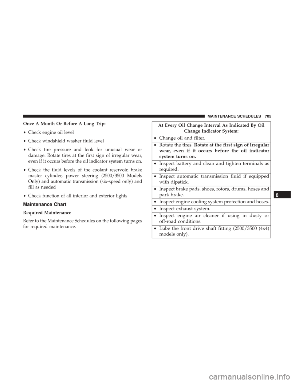
Once A Month Or Before A Long Trip:
•Check engine oil level
• Check windshield washer fluid level
• Check tire pressure and look for unusual wear or
damage. Rotate tires at the first sign of irregular wear,
even if it occurs before the oil indicator system turns on.
• Check the fluid levels of the coolant reservoir, brake
master cylinder, power steering (2500/3500 Models
Only) and automatic transmission (six-speed only) and
fill as needed
• Check function of all interior and exterior lights
Maintenance Chart
Required Maintenance
Refer to the Maintenance Schedules on the following pages
for required maintenance.
At Every Oil Change Interval As Indicated By Oil
Change Indicator System:
•Change oil and filter.
• Rotate the tires. Rotate at the first sign of irregular
wear, even if it occurs before the oil indicator
system turns on.
• Inspect battery and clean and tighten terminals as
required.
• Inspect automatic transmission fluid if equipped
with dipstick.
• Inspect brake pads, shoes, rotors, drums, hoses and
park brake.
• Inspect engine cooling system protection and hoses.
• Inspect exhaust system.
• Inspect engine air cleaner if using in dusty or
off-road conditions.
• Lube the front drive shaft fitting (2500/3500 (4x4)
models only). 8
MAINTENANCE SCHEDULES 705
Page 719 of 734

Shifting........................... .395, 405
Special Additives ........................ .670
Axle Fluid ........................... .668, 701
Axle Lubrication .......................... .668
Back-Up Camera .......................... .171
Bar, Stabilizer/Sway System ...................455
Battery .............................. .245, 648
Charging System Light ....................245
Keyless Key Fob Replacement ................25
Belts, Seat .................................95
Body Builders Guide ..........................6
Body Mechanism Lubrication ..................656
B-Pillar Location .......................... .513
Brake Assist System ........................ .497
Brake Control System, Electronic ................495
Brake Fluid .......................... .667, 701
Brake System ......................... .494, 667
Fluid Check ........................... .667
Master Cylinder ........................ .667
Parking .............................. .492
Warning Light .......................... .242
Brake/Transmission Interlock ..................387
Bulb Replacement ...................... .688, 690Bulbs, Light
........................... .98, 688
Cab Top Clearance Lights .....................694
Camera, Rear ............................ .171
Camper ................................ .220
Capacities, Fluid .......................... .697
Caps, Filler Oil (Engine) ........................... .642
Power Steering ......................... .492
Radiator (Coolant Pressure) .................664
Carbon Monoxide Warning .................95, 545
Cargo Light ............................. .146
Car Washes .............................. .673
Center High Mounted Stop Light ...............693
Center
Seat Storage Compartment ...............195
Certification Label ......................... .549
Chart, Tire Sizing .......................... .509
Check Engine Light (Malfunction Indicator Light). . . .637
Checking Your Vehicle For Safety ................94
Checks, Safety .............................94
Child Restraint .............................69
Child Restraints Booster Seats ............................73
Child Restraints ..........................69
Child Seat Installation ...................82, 85
10
INDEX 717
Page 723 of 734

Fuel, Flexible............................. .545
Fuses .................................. .679
Garage Door Opener (HomeLink) ............175, 180
Gas Cap (Fuel Filler Cap) .................549, 637
Gasoline, Clean Air ........................ .542
Gasoline (Fuel) ........................... .541
Gasoline, Reformulated ..................... .542
Gear Ranges .......................... .396, 405
Gear Select Lever Override ....................623
General Information ........................ .540
Glass Cleaning ........................... .677
Grocery Bag Retainer ....................... .200
Gross Axle Weight Rating .....................552
Gross Vehicle Weight Rating ...................551
Guide, Body Builders .........................6
GVWR ................................. .550
Hazard Driving Through Flowing, Rising, Or
Shallow Standing Water ....................472
Hazard Warning Flasher ..................... .580
Headlights .............................. .690
Automatic ............................ .139
Cleaning .............................. .677High Beam
............................ .147
High Beam/Low Beam Select Switch ...........147
Passing ............................... .147
Switch ............................... .139
Head Restraints ........................... .129
Heated Mirrors .........................115,200
Heater ................................. .330
Heater, Engine Block ....................... .385
High Beam/Low Beam Select (Dimmer) Switch .....147
Hill Descent Control ....................... .505
Hill Descent Control Indicator .................505
Hill Start Assist ........................... .498
Hitches Trailer Towing .......................... .558
Hoisting ................................ .618
HomeLink
(Garage Door Opener) ...............175
Hood Release ............................ .136
Hub Caps ............................... .617
Ignition ..................................15
Key.................................11,15
Ignition Key Removal ........................15
Illuminated Entry ...........................21
Immobilizer (Sentry Key) ......................17
Inside Rearview Mirror ...................104, 110
10
INDEX 721
Page 725 of 734

Exterior................................98
Fog........................... .142, 256, 691
Four-Wheel Drive Indicator .................417
Hazard Warning Flasher ...................580
Headlights ............................ .139
High Beam ............................ .147
High Beam/Low Beam Select ................147
Hill Descent Control Indicator ...............505
Illuminated Entry .........................21
Interior ..................... .143, 144, 145, 174
Low Fuel ............................. .254
Malfunction Indicator (Check Engine) ..........249
Park ................................. .262
Passing ............................... .147
Seat Belt Reminder ...................... .241
Security Alarm ......................... .244
Service ............................ .688, 690
Side Marker ........................... .696
Tire Pressure Monitoring (TPMS) ..........252, 535
Traction Control ........................ .503
Transfer Case .......................... .417
Turn Signal ................98, 146, 263, 690, 692
Warning (Instrument Cluster Description) . . . .244, 263
Limited-Slip Differential ..................470, 669 Loading Vehicle
........................... .549
Tires................................. .513
Load Shed Battery Saver Mode ...................... .282
Battery Saver On ........................ .282
Electrical Load Reduction ...................282
Intelligent Battery Sensor ...................282
Locks ....................................32
Automatic Door ..........................34
Child Protection ..........................34
Door ..................................32
Power Door .............................33
Low Tire Pressure System .....................535
Lubrication, Body ......................... .656
Lug
Nuts ............................... .581
Maintenance Free Battery .....................648
Maintenance Procedures ..................... .639
Maintenance Schedule ...................... .704
Malfunction Indicator Light (Check Engine) . . . .249, 637
Manual, Service ........................... .714
Manual Transmission Fluid Level Check ....................... .669
Lubricant Selection ...................... .701
10
INDEX 723