Maintaining Ram 1500 2017 Manual PDF
[x] Cancel search | Manufacturer: RAM, Model Year: 2017, Model line: 1500, Model: Ram 1500 2017Pages: 734, PDF Size: 7.3 MB
Page 684 of 734
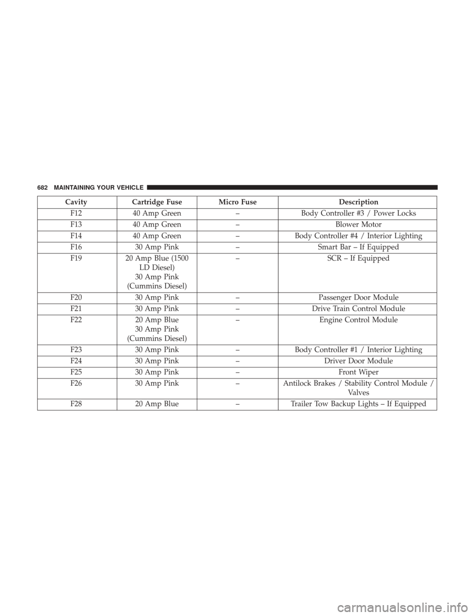
CavityCartridge Fuse Micro Fuse Description
F12 40 Amp Green –Body Controller #3 / Power Locks
F13 40 Amp Green –Blower Motor
F14 40 Amp Green –Body Controller #4 / Interior Lighting
F16 30 Amp Pink –Smart Bar – If Equipped
F19 20 Amp Blue (1500
LD Diesel)
30 Amp Pink
(Cummins Diesel) –
SCR – If Equipped
F20 30 Amp Pink –Passenger Door Module
F21 30 Amp Pink –Drive Train Control Module
F22 20 Amp Blue
30 Amp Pink
(Cummins Diesel) –
Engine Control Module
F23 30 Amp Pink –Body Controller #1 / Interior Lighting
F24 30 Amp Pink –Driver Door Module
F25 30 Amp Pink – Front Wiper
F26 30 Amp Pink –Antilock Brakes / Stability Control Module /
Valves
F28 20 Amp Blue –Trailer Tow Backup Lights – If Equipped
682 MAINTAINING YOUR VEHICLE
Page 685 of 734

CavityCartridge Fuse Micro Fuse Description
F29 20 Amp Blue –Trailer Tow Parking Lights – If Equipped
F30 30 Amp Pink –Trailer Tow Receptacle
F31 30 Amp Pink (1500
LD Diesel) –
Urea Heater Control – If Equipped
F32 –– Spare Fuse
F33 20 Amp Blue –Special Services Vehicle Only
F34 30 Amp Pink –Vehicle System Interface Module #2 –
If Equipped
F35 30 Amp Pink –Sunroof – If Equipped
F36 30 Amp Pink –Rear Defroster – If Equipped
F37 30 Amp Pink –Cummins Diesel Fuel Heater #2 –
If Equipped
F38 30 Amp Pink –Power Inverter 115V AC – If Equipped
F39 20 Amp Blue –Power Outlet – Special Services Only
F41 –10 Amp Red Active Grill Shutter – If Equipped
F42 –20 Amp Yellow Horn
F44 –10 Amp Red Diagnostic Port
7
MAINTAINING YOUR VEHICLE 683
Page 686 of 734

CavityCartridge Fuse Micro Fuse Description
F46 –10 Amp Red Upfitter – If Equipped
F49 –10 Amp Red Instrument Panel Cluster
(Except Fleet Vehicles)
F50 –20 Amp Yellow Air Suspension Control Module –
If Equipped
F51 –10 Amp Red Ignition Node Module / Keyless Ignition
(Instrument Panel Cluster –Fleet Vehicles Only)
F52 –5 Amp Tan Battery Sensor
F53 –20 Amp Yellow Trailer Tow – Left Turn/Stop Lights
F54 –20 Amp Yellow Adjustable Pedals
F56 –15 Amp Blue Additional Diesel Content – If Equipped
F57 –20 Amp Yellow Transmission
F58 –20 Amp Yellow Spare Fuse
F59 –10 Amp Red SCR Relay – If Equipped
F60 –15 Amp Blue Underhood Lamp
F61 –10 Amp Red (1500
LD Diesel &
Cummins Diesel) PM Sensor – If Equipped
684 MAINTAINING YOUR VEHICLE
Page 687 of 734
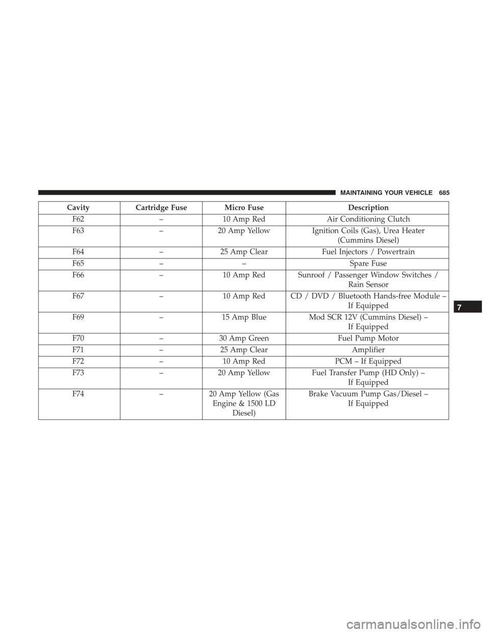
CavityCartridge Fuse Micro Fuse Description
F62 –10 Amp Red Air Conditioning Clutch
F63 –20 Amp Yellow Ignition Coils (Gas), Urea Heater
(Cummins Diesel)
F64 –25 Amp Clear Fuel Injectors / Powertrain
F65 –– Spare Fuse
F66 –10 Amp Red Sunroof / Passenger Window Switches /
Rain Sensor
F67 –10 Amp Red CD / DVD / Bluetooth Hands-free Module –
If Equipped
F69 –15 Amp Blue Mod SCR 12V (Cummins Diesel) –
If Equipped
F70 –30 Amp Green Fuel Pump Motor
F71 –25 Amp Clear Amplifier
F72 –10 Amp Red PCM – If Equipped
F73 –20 Amp Yellow Fuel Transfer Pump (HD Only) –
If Equipped
F74 –20 Amp Yellow (Gas
Engine & 1500 LD Diesel) Brake Vacuum Pump Gas/Diesel –
If Equipped
7
MAINTAINING YOUR VEHICLE 685
Page 688 of 734
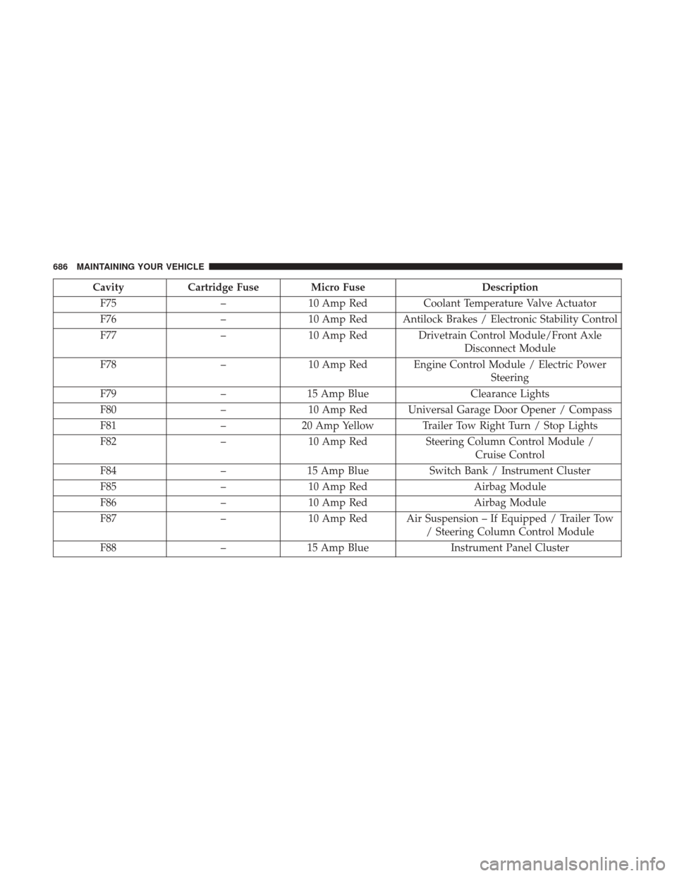
CavityCartridge Fuse Micro Fuse Description
F75 –10 Amp Red Coolant Temperature Valve Actuator
F76 –10 Amp Red Antilock Brakes / Electronic Stability Control
F77 –10 Amp Red Drivetrain Control Module/Front Axle
Disconnect Module
F78 –10 Amp Red Engine Control Module / Electric Power
Steering
F79 –15 Amp Blue Clearance Lights
F80 –10 Amp Red Universal Garage Door Opener / Compass
F81 –20 Amp Yellow Trailer Tow Right Turn / Stop Lights
F82 –10 Amp Red Steering Column Control Module /
Cruise Control
F84 –15 Amp Blue Switch Bank / Instrument Cluster
F85 –10 Amp Red Airbag Module
F86 –10 Amp Red Airbag Module
F87 –10 Amp Red Air Suspension – If Equipped / Trailer Tow
/ Steering Column Control Module
F88 –15 Amp Blue Instrument Panel Cluster
686 MAINTAINING YOUR VEHICLE
Page 689 of 734

CavityCartridge Fuse Micro Fuse Description
F90/F91 –20 Amp Yellow Power Outlet (Rear Seats)
Customer Selectable
F93 –20 Amp Yellow Cigar Lighter
F94 –10 Amp Red Shifter / Transfer Case Module
F95 –10 Amp Red Rear Camera / Park Assist
F96 –10 Amp Red Rear Seat Heater Switch
F97 –25 Amp Clear Rear Heated Seats & Heated Steering Wheel
– If Equipped
F98 –25 Amp Clear Front Heated Seats – If Equipped
F99 –10 Amp Red Climate Control
F100 –10 Amp Red Upfitters – If Equipped
F101 –15 Amp Blue Electrochromatic Mirror / Smart High Beams
– If Equipped
F104 –20 Amp Yellow
Power Outlets (Instrument Panel /
Center Console)
7
MAINTAINING YOUR VEHICLE 687
Page 690 of 734
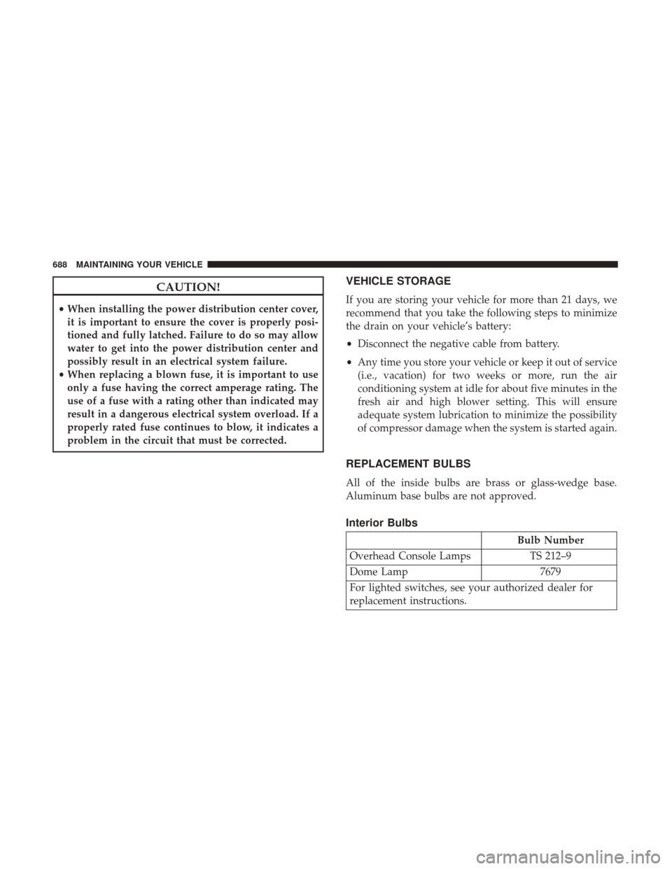
CAUTION!
•When installing the power distribution center cover,
it is important to ensure the cover is properly posi-
tioned and fully latched. Failure to do so may allow
water to get into the power distribution center and
possibly result in an electrical system failure.
• When replacing a blown fuse, it is important to use
only a fuse having the correct amperage rating. The
use of a fuse with a rating other than indicated may
result in a dangerous electrical system overload. If a
properly rated fuse continues to blow, it indicates a
problem in the circuit that must be corrected.
VEHICLE STORAGE
If you are storing your vehicle for more than 21 days, we
recommend that you take the following steps to minimize
the drain on your vehicle’s battery:
• Disconnect the negative cable from battery.
• Any time you store your vehicle or keep it out of service
(i.e., vacation) for two weeks or more, run the air
conditioning system at idle for about five minutes in the
fresh air and high blower setting. This will ensure
adequate system lubrication to minimize the possibility
of compressor damage when the system is started again.
REPLACEMENT BULBS
All of the inside bulbs are brass or glass-wedge base.
Aluminum base bulbs are not approved.
Interior Bulbs
Bulb Number
Overhead Console Lamps TS 212–9
Dome Lamp 7679
For lighted switches, see your authorized dealer for
replacement instructions.
688 MAINTAINING YOUR VEHICLE
Page 691 of 734

Exterior Bulbs
Bulb Number
Base Quad Headlamp –
Low Beam H11LL
Base Quad Headlamp –
High Beam 9005LL
Front Turn Signal Lamp
(Base Quad Headlamp) 3157NA
Premium Bi Halogen
Projector Headlamp - Low
Beam 9005Sl+
Premium Bi Halogen
Projector Headlamp -
High Beam 9005LL
Front Turn Signal Lamp
(Premium Headlamp) LED (Serviced at autho-
rized dealer)
Fog Lamp (Horizontal
shape) 9145
Fog Lamp (Vertical shape) 9006
Center High Mounted
Stop Lamp (CHMSL) 921K
Rear Cargo Lamp 921
Bulb Number
LED Center High
Mounted Stop Lamp
(CHMSL)/Cargo Lamp LED (Serviced at autho-
rized dealer)
Cab Roof Marker Lamps 194NA
Base Rear Tail/Turn and
Stop Lamp 3157K
Premium Rear Tail/Turn
and Stop Lamp LED (Serviced at autho-
rized dealer)
Premium Backup Lamp 7440/W21W
Rear Lamp Bar ID Marker
Lamp 194
Side Marker Lamps (Dual
Rear Wheels) 194
Backup Lamp 921
Rear License Plate Lamp 194
7
MAINTAINING YOUR VEHICLE 689
Page 692 of 734

BULB REPLACEMENT
NOTE:Lens fogging can occur under certain atmospheric
conditions. This will usually clear as atmospheric condi-
tions change to allow the condensation to change back into
a vapor. Turning the lamps on will usually accelerate the
clearing process.
Base Quad / Premium Bi-Halogen: Low Beam
Headlamp, High Beam Headlamp, Front Park And
Turn — If Equipped
1. Open the hood.
2. Disconnect and isolate the negative battery cable.
3. Remove the six plastic push-in fasteners that secure the upper radiator seal to the grille support and both fender
ledges.
4. Remove the two plastic push-in rivets that secure the upper radiator seal to the radiator.
5. Remove the upper radiator seal from the vehicle. 6. Remove the two headlamp assembly attachment screws.
7. Reach into the front wheel house ahead of the front
wheel, remove the fastener, and lift the cover over the
access hole in the front of the wheel house splash shield.
Access to the rear of the lamp can be gained through this
access hole.
Headlamp Assembly Attachment Screw Locations
690 MAINTAINING YOUR VEHICLE
Page 693 of 734

8. Reach through the access hole of the wheel house splashshield and lift the slide lock upward far enough to
disengage it from the lock post on the back of the front
lamp unit housing.
9. Remove the headlamp assembly. Grasp the outboard edge of the lamp and pull it straight forward to disen-
gage the ball stud from the plastic grommet.
10. Disconnect the wiring harness connectors from the bulb socket.
11. Replace bulb(s) as necessary.CAUTION!
• Do not contaminate the bulb glass by touching it
with your fingers or by allowing it to contact other
oily surfaces. Shortened bulb life will result.
• Always use the correct bulb size and type for replace-
ment. An incorrect bulb size or type may overheat
and cause damage to the lamp, the bulb socket, or the
lamp wiring.
NOTE: There are access covers over both headlamp bulb
access holes in the quad front lamp unit housing (if
equipped). These covers MUST be reinstalled after the bulb
has been replaced.
Fog Lamps — If Equipped
1. Reach under and behind the front bumper to access the back of the front fog lamp housing.
2. Disconnect the fog lamp wiring harness connector from the fog lamp bulb.
3. Rotate the bulb counterclockwise ¼ turn to unlock the bulb from the housing.
4. Pull the bulb straight out from the housing.Slide Lock
7
MAINTAINING YOUR VEHICLE 691