Engine battery Ram 1500 2017 Owner's Manual
[x] Cancel search | Manufacturer: RAM, Model Year: 2017, Model line: 1500, Model: Ram 1500 2017Pages: 734, PDF Size: 7.3 MB
Page 14 of 734

Keyless Push Button Ignition — If Equipped
This feature allows the driver to operate the ignition switch
with the push of a button as long as the Remote Keyless
Entry key fob is in the passenger compartment.
The Keyless Push Button Ignition has four operating
positions; three of which are labeled and will illuminate
when in position. The three positions are OFF, ACC, and
ON/RUN. The fourth position is START, during start RUN
will illuminate.
NOTE:In case the ignition switch does not change with
the push of a button, the key fob may have a low or dead
battery. In this situation, a back up method can be used to
operate the ignition switch. Put the nose side (side opposite
of the emergency key) of the key fob against the ENGINE
START/STOP button, with your foot applied on the brake
pedal, and push to operate the ignition switch.
Keyless Push Button Ignition
1—OFF
2 — ACC (ACCESSORY)
3 — ON/RUN
12 THINGS TO KNOW BEFORE STARTING YOUR VEHICLE
Page 16 of 734
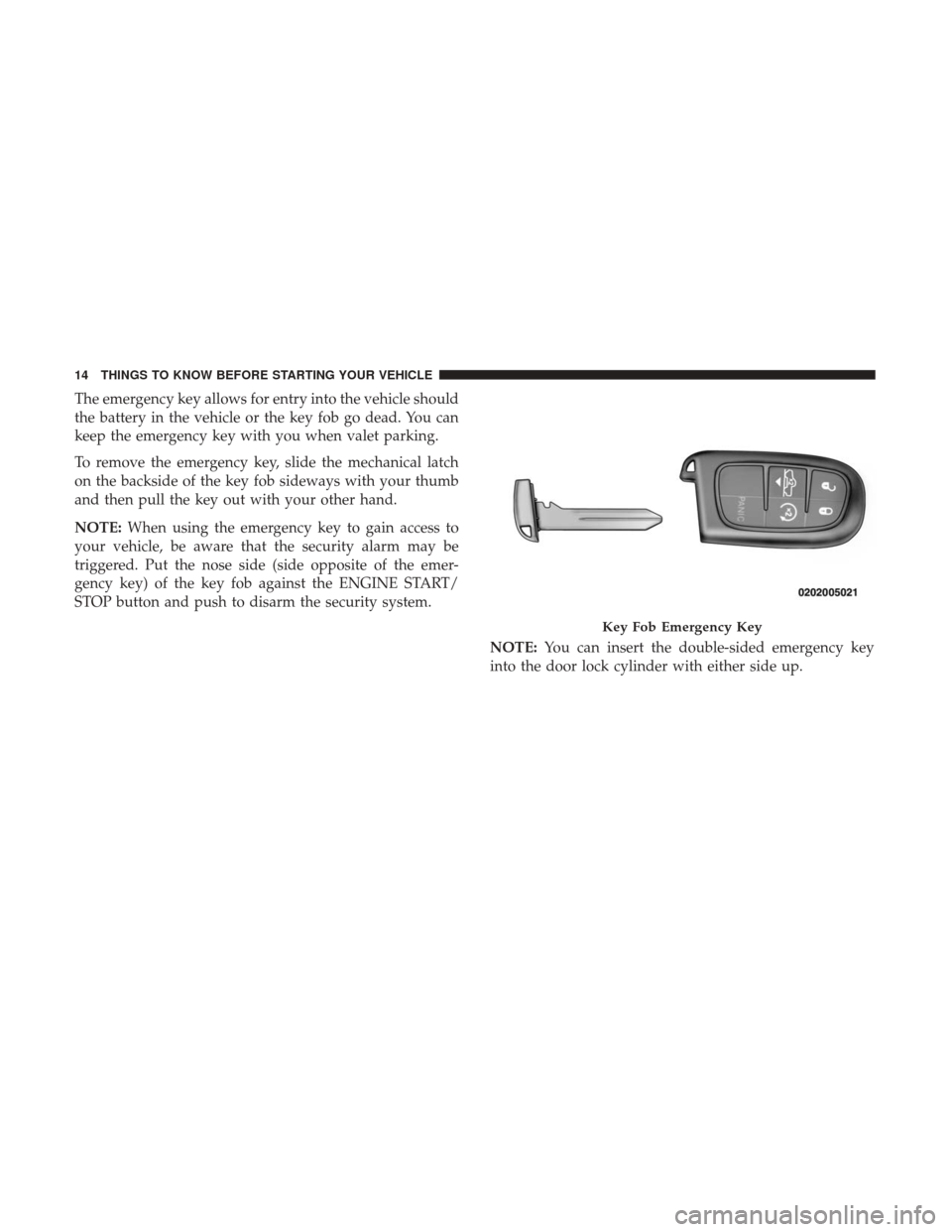
The emergency key allows for entry into the vehicle should
the battery in the vehicle or the key fob go dead. You can
keep the emergency key with you when valet parking.
To remove the emergency key, slide the mechanical latch
on the backside of the key fob sideways with your thumb
and then pull the key out with your other hand.
NOTE:When using the emergency key to gain access to
your vehicle, be aware that the security alarm may be
triggered. Put the nose side (side opposite of the emer-
gency key) of the key fob against the ENGINE START/
STOP button and push to disarm the security system.
NOTE:You can insert the double-sided emergency key
into the door lock cylinder with either side up.
Key Fob Emergency Key
14 THINGS TO KNOW BEFORE STARTING YOUR VEHICLE
Page 31 of 734
REMOTE STARTING SYSTEM — IF EQUIPPED
This system uses the key fob to start the engine
conveniently from outside the vehicle while still
maintaining security. The system has a range of
approximately 300 ft (91 m).
NOTE:
• The vehicle must be equipped with an automatic trans-
mission to be equipped with Remote Start.
• Obstructions between the vehicle and the key fob may
reduce this range.
How To Use Remote Start
All of the following conditions must be met before the
engine will remote start:
• Gear selector in PARK
• Doors closed
• Hood closed
• HAZARD switch off
• BRAKE switch inactive (brake pedal not pushed)
• Ignition key removed from ignition switch •
Battery at an acceptable charge level
• PANIC button not pushed
• Fuel meets minimum requirement
• System not disabled from previous remote start event
• Vehicle security alarm not active
WARNING!
•Do not start or run an engine in a closed garage or
confined area. Exhaust gas contains Carbon Monox-
ide (CO) which is odorless and colorless. Carbon
Monoxide is poisonous and can cause serious injury
or death when inhaled.
• Keep key fobs away from children. Operation of the
Remote Start System, windows, door locks or other
controls could cause serious injury or death.
2
THINGS TO KNOW BEFORE STARTING YOUR VEHICLE 29
Page 59 of 734
•Seat Belt Pretensioners
• Seat Belt Buckle Switch
Air Bag Warning Light
The ORC monitors the readiness of the electronic
parts of the air bag system whenever the ignition
switch is in the START or ON/RUN position. If
the ignition switch is in the OFF position or in the
ACC position, the air bag system is not on and the air bags
will not inflate.
The ORC contains a backup power supply system that may
deploy the air bag system even if the battery loses power or
it becomes disconnected prior to deployment.
The ORC turns on the Air Bag Warning Light in the
instrument panel for approximately four to eight seconds
for a self-check when the ignition switch is first in the
ON/RUN position. After the self-check, the Air Bag Warn-
ing Light will turn off. If the ORC detects a malfunction in
any part of the system, it turns on the Air Bag Warning
Light, either momentarily or continuously. A single chime
will sound to alert you if the light comes on again after
initial startup. The ORC also includes diagnostics that will illuminate the
instrument panel Air Bag Warning Light if a malfunction is
detected that could affect the air bag system. The diagnos-
tics also record the nature of the malfunction. While the air
bag system is designed to be maintenance free, if any of the
following occurs, have an authorized dealer service the air
bag system immediately.
•
The Air Bag Warning Light does not come on during the
four to eight seconds when the ignition switch is first in
the ON/RUN position.
• The Air Bag Warning Light remains on after the four to
eight-second interval.
• The Air Bag Warning Light comes on intermittently or
remains on while driving.
NOTE: If the speedometer, tachometer, or any engine
related gauges are not working, the Occupant Restraint
Controller (ORC) may also be disabled. In this condition
the air bags may not be ready to inflate for your protection.
Have an authorized dealer service the air bag system
immediately.
2
THINGS TO KNOW BEFORE STARTING YOUR VEHICLE 57
Page 68 of 734
Do not drive your vehicle after the air bags have deployed.
If you are involved in another collision, the air bags will
not be in place to protect you.
WARNING!
Deployed air bags and seat belt pretensioners cannot
protect you in another collision. Have the air bags, seat
belt pretensioners, and the seat belt retractor assem-
blies replaced by an authorized dealer immediately.
Also, have the Occupant Restraint Controller System
serviced as well.
NOTE:
• Air bag covers may not be obvious in the interior trim,
but they will open during air bag deployment.
• After any collision, the vehicle should be taken to an
authorized dealer immediately.
Enhanced Accident Response System
In the event of an impact, if the communication network
remains intact, and the power remains intact, depending
on the nature of the event, the ORC will determine whether
to have the Enhanced Accident Response System perform
the following functions:
• Cut off fuel to the engine.
• Flash hazard lights as long as the battery has power or
until the hazard light button is pressed. The hazard
lights can be deactivated by pressing the hazard light
button.
• Turn on the interior lights, which remain on as long as
the battery has power.
• Unlock the power door locks.
66 THINGS TO KNOW BEFORE STARTING YOUR VEHICLE
Page 178 of 734

Before You Begin Programming HomeLink
Ensure your vehicle is parked outside of the garage before
you begin programming.
For efficient programming and accurate transmission of
the radio-frequency signal it is recommended that a new
battery be placed in the hand-held transmitter of the device
that is being programmed to the HomeLink system.
To erase the channels place the ignition in the ON/RUN
position and push and hold the two outside HomeLink
buttons (I and III) for up to 20 seconds. The instrument
cluster display will display “CLEARING CHANNELS.”
Release the buttons when “CHANNELS CLEARED” ap-
pears on the display.
NOTE:
•For vehicle’s equipped with Keyless Enter-N-Go, place
the ignition in the RUN position with the Engine ON.
• Erasing all channels should only be performed when
programming HomeLink for the first time. Do not erase
channels when programming additional buttons.
• If you have any problems, or require assistance, please
call toll-free 1-800-355-3515 or, on the Internet at
HomeLink.com for information or assistance.
Programming A Rolling Code
For programming garage door openers that were manufac-
tured after 1995. These garage door openers can be identi-
fied by the “LEARN” or “TRAIN” button located where
the hanging antenna is attached to the garage door opener.
It is NOT the button that is normally used to open and
close the door. The name and color of the button may vary
by manufacturer.
Training The Garage Door Opener
1 — Door Opener
2 — Training Button
176 UNDERSTANDING THE FEATURES OF YOUR VEHICLE
Page 182 of 734

Reprogramming A Single HomeLink Button
(Canadian/Gate Operator)
To reprogram a channel that has been previously trained,
follow these steps:
1. Turn the ignition switch to the ON/RUN position.
For vehicle’s equipped with Keyless Enter-N-Go, place the
ignition in the RUN position with the Engine ON.
2. Push and hold the desired HomeLink button until theinstrument cluster display shows “CHANNEL #
TRAINING” Do not release the button.
3. Without releasing the button proceed with “Canadian/
Gate Operator Programming” Step 2 and follow all
remaining steps.
Using HomeLink
To operate, push and release the programmed HomeLink
button. Activation will now occur for the programmed
device (i.e. garage door opener, gate operator, security
system, entry door lock, home/office lighting, etc.) The
hand-held transmitter of the device may also be used at
any time.
Security
It is advised to erase all channels before you sell or turn in
your vehicle.
To erase the channels press and hold the two outside
HomeLink buttons (I and III) for up 20 seconds. The
instrument cluster display will display “CLEARING
CHANNELS.” Release the buttons when the instrument
cluster display shows “CHANNELS CLEARED.”
The HomeLink Universal Transceiver is disabled when the
Vehicle Security Alarm is active.
Troubleshooting Tips
If you are having trouble programming HomeLink, here
are some of the most common solutions:
• Replace the battery in the Garage Door Opener hand-
held transmitter.
• Push the LEARN button on the Garage Door Opener to
complete the training for a Rolling Code.
• Did you unplug the device for programming and re-
member to plug it back in?
180 UNDERSTANDING THE FEATURES OF YOUR VEHICLE
Page 190 of 734
When the vehicle is turned off, be sure to unplug any
equipment as to not drain the battery of the vehicle. All
accessories connected to the outlet(s) should be removed or
turned off when the vehicle is not in use to protect the
battery against discharge.
WARNING!
To avoid serious injury or death:
•Only devices designed for use in this type of outlet
should be inserted into any 12 Volt outlet.
• Do not touch with wet hands.
• Close the lid when not in use and while driving the
vehicle.
• If this outlet is mishandled, it may cause an electric
shock and failure.
CAUTION!
• Many accessories that can be plugged in draw power
from the vehicle’s battery, even when not in use (i.e.,
cellular phones, etc.). Eventually, if plugged in long
enough, the vehicle’s battery will discharge suffi-
ciently to degrade battery life and/or prevent the
engine from starting.
• Accessories that draw higher power (i.e., coolers,
vacuum cleaners, lights, etc.), will discharge the
battery even more quickly. Only use these intermit-
tently and with greater caution.
(Continued)
Power Outlet Fuse Locations
1 — F104 Fuse 20 A Yellow Power Outlet Center Console Bin / USB
Port (Charge Only)
2 — F90–F91 Fuse 20 A Yellow Power Outlet Rear Center Console
3 — F93 Fuse 20 A Yellow Cigar Lighter Instrument Panel 188 UNDERSTANDING THE FEATURES OF YOUR VEHICLE
Page 203 of 734
NOTE:To prevent excessive battery drain, use the rear
window defroster only when the engine is operating.
CAUTION!
Failure to follow these cautions can cause damage to
the heating elements:
• Use care when washing the inside of the rear win-
dow. Do not use abrasive window cleaners on the
interior surface of the window. Use a soft cloth and a
mild washing solution, wiping parallel to the heat-
ing elements. Labels can be peeled off after soaking
with warm water.
•
Do not use scrapers, sharp instruments, or abrasive
window cleaners on the interior surface of the window.
• Keep all objects a safe distance from the window.
Power Sliding Rear Window — If Equipped
The switch for the power sliding rear window is located on
the overhead console.
Push the switch to the right to open the glass. Pull the
switch to the left to close the glass.
Rear Window Switch
3
UNDERSTANDING THE FEATURES OF YOUR VEHICLE 201
Page 241 of 734
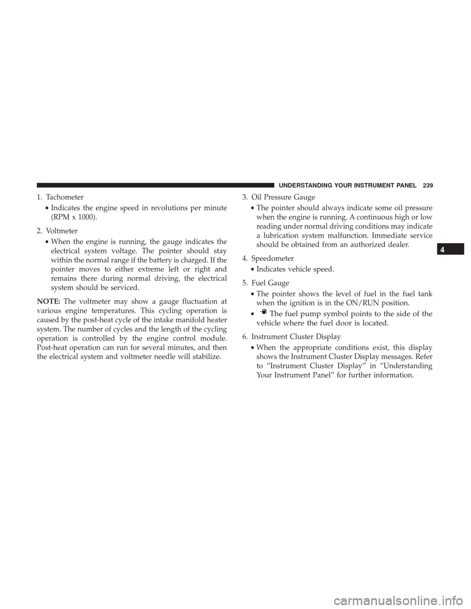
1. Tachometer•Indicates the engine speed in revolutions per minute
(RPM x 1000).
2. Voltmeter •When the engine is running, the gauge indicates the
electrical system voltage. The pointer should stay
within the normal range if the battery is charged. If the
pointer moves to either extreme left or right and
remains there during normal driving, the electrical
system should be serviced.
NOTE: The voltmeter may show a gauge fluctuation at
various engine temperatures. This cycling operation is
caused by the post-heat cycle of the intake manifold heater
system. The number of cycles and the length of the cycling
operation is controlled by the engine control module.
Post-heat operation can run for several minutes, and then
the electrical system and voltmeter needle will stabilize. 3. Oil Pressure Gauge
•The pointer should always indicate some oil pressure
when the engine is running. A continuous high or low
reading under normal driving conditions may indicate
a lubrication system malfunction. Immediate service
should be obtained from an authorized dealer.
4. Speedometer •Indicates vehicle speed.
5. Fuel Gauge •The pointer shows the level of fuel in the fuel tank
when the ignition is in the ON/RUN position.
•
The fuel pump symbol points to the side of the
vehicle where the fuel door is located.
6. Instrument Cluster Display
•When the appropriate conditions exist, this display
shows the Instrument Cluster Display messages. Refer
to “Instrument Cluster Display” in “Understanding
Your Instrument Panel” for further information.
4
UNDERSTANDING YOUR INSTRUMENT PANEL 239