outside temp Ram 1500 2018 Owner's Manual
[x] Cancel search | Manufacturer: RAM, Model Year: 2018, Model line: 1500, Model: Ram 1500 2018Pages: 700, PDF Size: 8.86 MB
Page 62 of 700
•Do not reposition the head restraint 180 degrees to the
incorrect position in an attempt to gain additional clear-
ance to the back of the head.
Front Head Restraint Removal
To remove the head restraint, raise it up as far as it can go.
Then, push the adjustment button and the release button at
the base of each post while pulling the head restraint up. To
reinstall the head restraint, put the head restraint posts into
the holes. Then, adjust it to the appropriate height.
NOTE: Do not reposition the head restraint 180 degrees to
the incorrect position in an attempt to gain additional
clearance to the back of the head.
WARNING!
• A loose head restraint thrown forward in a collision
or hard stop could cause serious injury or death to
occupants of the vehicle. Always securely stow re-
moved head restraints in a location outside the
occupant compartment.
• ALL the head restraints MUST be reinstalled in the
vehicle to properly protect the occupants. Follow the
re-installation instructions above prior to operating
the vehicle or occupying a seat.
Rear Head Restraint Removal
To remove the head restraint, push the adjustment button
and the release button while pulling upward on the whole
assembly. To reinstall the head restraint, put the head
restraint posts into the holes and adjust it to the appropri-
ate height.
NOTE: To remove outboard restraints, the rear seat bottom
must be folded up.
WARNING!
• A loose head restraint thrown forward in a collision
or hard stop could cause serious injury or death to
occupants of the vehicle. Always securely stow re-
moved head restraints in a location outside the
occupant compartment.
• ALL the head restraints MUST be reinstalled in the
vehicle to properly protect the occupants. Follow the
re-installation instructions above prior to operating
the vehicle or occupying a seat.
60 GETTING TO KNOW YOUR VEHICLE
Page 71 of 700

Resetting The Power Folding Outside Mirrors
You may need to reset the power folding mirrors if the
following occurs:
•The mirrors are accidentally blocked while folding.
• The mirrors are accidentally manually folded/unfolded.
• The mirrors come out of the unfolded position.
• The mirrors shake and vibrate at normal driving speeds.
To Reset The Power Folding Mirrors:
1. Using the power folding mirror switch, move the mirror to its full forward position.
2. Using the power folding mirror switch, move the mirror to the full retract position (this may require multiple
button pushes). This resets them to their normal posi-
tion. NOTE:
•
The power fold mirrors are designed to operate while
the vehicle is stationary or traveling at moderate speeds.
If you attempt to power fold the mirrors at high speeds
they may not fully open or close. You should slow down
to a moderate speed and complete the operation.
• When pushing the power fold button 10 or more times
in one minute the system shuts down for one minute to
protect the motors from over heating.
3
GETTING TO KNOW YOUR VEHICLE 69
Page 87 of 700
Mist Feature
When a single wipe to clear off road mist or spray from a
passing vehicle is needed, push the washer knob, located
on the end of the multifunction lever, inward to the first
detent and release. The wipers will cycle one time and
automatically shut off.
NOTE:The mist feature does not activate the washer
pump; therefore, no washer fluid will be sprayed on the
windshield. The wash function must be used in order to
spray the windshield with washer fluid.
Rain Sensing Wipers — If Equipped
This feature senses moisture on the windshield and auto-
matically activates the wipers for the driver. The feature is
especially useful for road splash or overspray from the
windshield washers of the vehicle ahead. Rotate the end of
the multifunction lever to one of five settings to activate
this feature.
NOTE: This feature can be programmed through the
Uconnect system. Refer to “Uconnect Settings” in “Multi-
media” for further information.
The sensitivity of the system can be adjusted with the
multifunction lever. Wiper delay position 1 is the least
sensitive, and wiper delay position 5 is the most sensitive. Position 3 should be used for normal rain conditions.
Positions 1 and 2 can be used if the driver desires less
wiper sensitivity. Positions 4 and 5 can be used if the driver
desires more sensitivity. Place the wiper switch in the
O (off) position when not using the system.
NOTE:
•
The Rain Sensing feature will not operate when the
wiper switch is in the low or high-speed position.
• The Rain Sensing feature may not function properly
when ice, or dried salt water is present on the wind-
shield.
• Use of Rain-X or products containing wax or silicone
may reduce Rain Sensing performance.
The Rain Sensing system has protection features for the
wiper blades and arms, and will not operate under the
following conditions:
• Low Ambient Temperature — When the ignition is first
turned ON, the Rain Sensing system will not operate
until the wiper switch is moved, vehicle speed is greater
than 0 mph (0 km/h), or the outside temperature is
greater than 32°F (0°C).
3
GETTING TO KNOW YOUR VEHICLE 85
Page 89 of 700

Manual Climate Control Descriptions
IconDescription
MAX A/C Setting
Rotate the Temperature Control Knob counterclockwise until it is set to MAX A/C. This is the
coldest setting and will put the A/C to its maximum power.
A/C Button
Push the A/C button to engage the Air Conditioning (A/C). A LED will illuminate when the
A/C system is engaged.
Recirculation Button
Push and release this button to change the system between recirculation mode and outside air
mode. Recirculation can be used when outside conditions such as smoke, odors, dust, or high
humidity are present.
NOTE:
•Continuous use of the Recirculation mode may make the inside air stuffy and window fog-
ging may occur. Extended use of this mode is not recommended.
•The use of the Recirculation mode in cold or damp weather could cause windows to fog on
the inside, because of moisture buildup inside the vehicle. Select the outside air position for
maximum defogging.
•Recirculation can be used in all modes except for Defrost.
•The A/C can be deselected manually without disturbing the mode control selection.
3
GETTING TO KNOW YOUR VEHICLE 87
Page 90 of 700
IconDescription
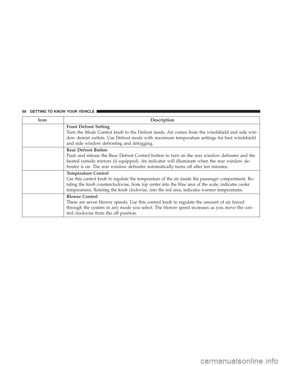
Front Defrost Setting
Turn the Mode Control knob to the Defrost mode. Air comes from the windshield and side win-
dow demist outlets. Use Defrost mode with maximum temperature settings for best windshield
and side window defrosting and defogging.
Rear Defrost Button
Push and release the Rear Defrost Control button to turn on the rear window defroster and the
heated outside mirrors (if equipped). An indicator will illuminate when the rear window de-
froster is on. The rear window defroster automatically turns off after ten minutes.
Temperature Control
Use this control knob to regulate the temperature of the air inside the passenger compartment. Ro-
tating the knob counterclockwise, from top center into the blue area of the scale, indicates cooler
temperatures. Rotating the knob clockwise, into the red area, indicates warmer temperatures.
Blower Control
There are seven blower speeds. Use this control knob to regulate the amount of air forced
through the system in any mode you select. The blower speed increases as you move the con-
trol clockwise from the off position.
88 GETTING TO KNOW YOUR VEHICLE
Page 95 of 700

IconDescription
Front Defrost Setting
Push the button to activate Defrost mode. Air comes from the windshield and side window de-
mist outlets. Use Defrost mode with maximum temperature settings for best windshield and
side window defrosting and defogging.
Rear Defrost Button
Push and release the Rear Defrost Control button to turn on the rear window defroster and the
heated outside mirrors (if equipped). An indicator will illuminate when the rear window de-
froster is on. The rear window defroster automatically turns off after ten minutes.
Temperature Control
Press the arrows on the touchscreen or faceplate to regulate the temperature of the air inside the
passenger compartment. Pressing the down arrow indicates cooler temperatures, and pressing
the up arrow indicates warmer temperatures.
Blower Control
There are seven blower speeds. Press the buttons to regulate the amount of air forced through
the system in any mode you select. The blower speed increases as you move the control clock-
wise from the off position.
3
GETTING TO KNOW YOUR VEHICLE 93
Page 101 of 700
IconDescription
AUTO Button — If Equipped
Automatically controls the interior cabin temperature by adjusting airflow distribution and
amount. Toggling this function will cause the system to switch between manual mode and auto-
matic modes. Refer to “Automatic Operation” for more information.
Front Defrost Button
Press and release the touchscreen button, or push and release the button on the faceplate, to
change the current airflow setting to Defrost mode. The indicator illuminates when this feature
is on. Air comes from the windshield and side window demist outlets. When the defrost button
is selected, the blower level may increase. Use Defrost mode with maximum temperature set-
tings for best windshield and side window defrosting and defogging. When toggling the front
defrost mode button, the climate system will return to previous setting.
Rear Defrost Button
Push and release the button on the touchscreen, or push and release the button on the faceplate,
to turn on the rear window defroster and the heated outside mirrors (if equipped). An indicator
will illuminate when the rear window defroster is on. The rear window defroster automatically
turns off after ten minutes.
3
GETTING TO KNOW YOUR VEHICLE 99
Page 177 of 700
Display Menu Screens
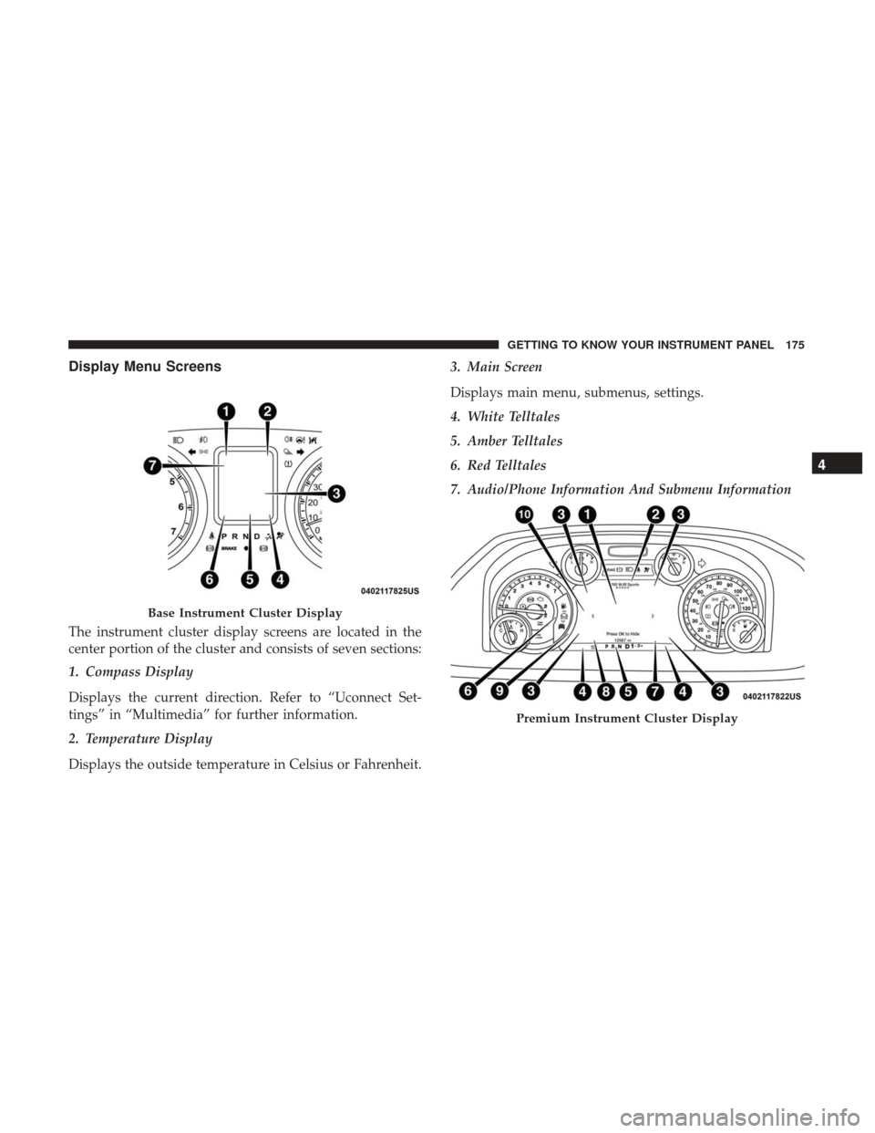
The instrument cluster display screens are located in the
center portion of the cluster and consists of seven sections:
1. Compass Display
Displays the current direction. Refer to “Uconnect Set-
tings” in “Multimedia” for further information.
2. Temperature Display
Displays the outside temperature in Celsius or Fahrenheit.3. Main Screen
Displays main menu, submenus, settings.
4. White Telltales
5. Amber Telltales
6. Red Telltales
7. Audio/Phone Information And Submenu Information
Base Instrument Cluster Display
Premium Instrument Cluster Display
4
GETTING TO KNOW YOUR INSTRUMENT PANEL 175
Page 178 of 700
The instrument cluster display screens are located in the
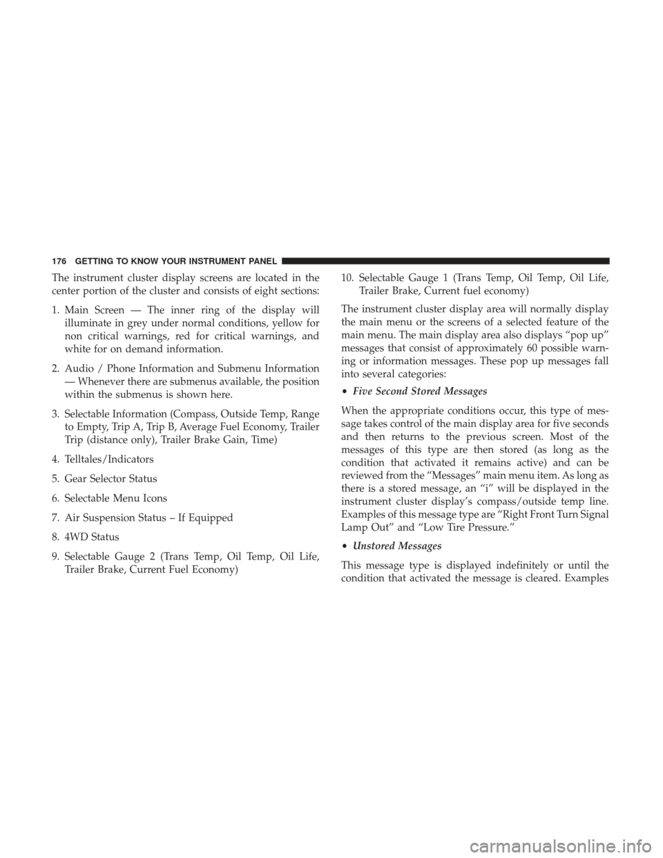
center portion of the cluster and consists of eight sections:
1. Main Screen — The inner ring of the display willilluminate in grey under normal conditions, yellow for
non critical warnings, red for critical warnings, and
white for on demand information.
2. Audio / Phone Information and Submenu Information — Whenever there are submenus available, the position
within the submenus is shown here.
3. Selectable Information (Compass, Outside Temp, Range to Empty, Trip A, Trip B, Average Fuel Economy, Trailer
Trip (distance only), Trailer Brake Gain, Time)
4. Telltales/Indicators
5. Gear Selector Status
6. Selectable Menu Icons
7. Air Suspension Status – If Equipped
8. 4WD Status
9. Selectable Gauge 2 (Trans Temp, Oil Temp, Oil Life, Trailer Brake, Current Fuel Economy) 10. Selectable Gauge 1 (Trans Temp, Oil Temp, Oil Life,
Trailer Brake, Current fuel economy)
The instrument cluster display area will normally display
the main menu or the screens of a selected feature of the
main menu. The main display area also displays “pop up”
messages that consist of approximately 60 possible warn-
ing or information messages. These pop up messages fall
into several categories:
• Five Second Stored Messages
When the appropriate conditions occur, this type of mes-
sage takes control of the main display area for five seconds
and then returns to the previous screen. Most of the
messages of this type are then stored (as long as the
condition that activated it remains active) and can be
reviewed from the “Messages” main menu item. As long as
there is a stored message, an “i” will be displayed in the
instrument cluster display’s compass/outside temp line.
Examples of this message type are “Right Front Turn Signal
Lamp Out” and “Low Tire Pressure.”
• Unstored Messages
This message type is displayed indefinitely or until the
condition that activated the message is cleared. Examples
176 GETTING TO KNOW YOUR INSTRUMENT PANEL
Page 218 of 700
•The vehicle is driven greater than 20 mph (32 km/h) for
greater than 70 seconds.
• The vehicle is driven greater than 40 mph (64 km/h)
(HDC exits immediately).
• HDC detects excessive brake temperature.
Feedback To The Driver
The instrument cluster has an HDC icon and the HDC
switch has an LED icon, which offers feedback to the driver
about the state HDC is in.
• The cluster icon and switch lamp will illuminate and
remain on solid when HDC is enabled or activated. This
is the normal operating condition for HDC.
• The cluster icon and switch lamp will flash for several
seconds then extinguish when the driver pushes the
HDC switch but enable conditions are not met.
• The cluster icon and switch lamp will flash for several
seconds then extinguish when HDC disables due to
excess speed.
• The cluster icon and switch lamp will flash when HDC
deactivates due to overheated brakes. The flashing will
stop and HDC will activate again once the brakes have
cooled sufficiently.WARNING!
HDC is only intended to assist the driver in controlling
vehicle speed when descending hills. The driver must
remain attentive to the driving conditions and is re-
sponsible for maintaining a safe vehicle speed.
AUXILIARY DRIVING SYSTEMS
Tire Pressure Monitoring System (TPMS)
The Tire Pressure Monitor System (TPMS) will warn the
driver of a low tire pressure based on the vehicle recom-
mended cold placard pressure.
The tire pressure will vary with temperature by about 1 psi
(7 kPa) for every 12°F (6.5°C). This means that when the
outside temperature decreases, the tire pressure will de-
crease. Tire pressure should always be set based on cold
inflation tire pressure. This is defined as the tire pressure
after the vehicle has not been driven for at least three
hours, or driven less than 1 mile (1.6 km) after a three hour
period. The cold tire inflation pressure must not exceed the
maximum inflation pressure molded into the tire sidewall.
216 SAFETY