change wheel Ram 1500 2018 Owner's Manual
[x] Cancel search | Manufacturer: RAM, Model Year: 2018, Model line: 1500, Model: Ram 1500 2018Pages: 372, PDF Size: 7.1 MB
Page 164 of 372
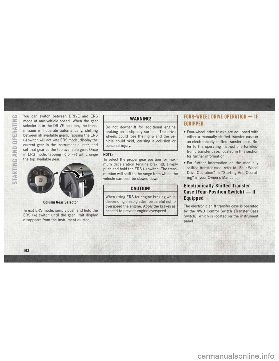
You can switch between DRIVE and ERS
mode at any vehicle speed. When the gear
selector is in the DRIVE position, the trans-
mission will operate automatically, shifting
between all available gears. Tapping the ERS
(-) switch will activate ERS mode, display the
current gear in the instrument cluster, and
set that gear as the top available gear. Once
in ERS mode, tapping (-) or (+) will change
the top available gear.
To exit ERS mode, simply push and hold the
ERS (+) switch until the gear limit display
disappears from the instrument cluster.WARNING!
Do not downshift for additional engine
braking on a slippery surface. The drive
wheels could lose their grip and the ve-
hicle could skid, causing a collision or
personal injury.
NOTE:
To select the proper gear position for maxi-
mum deceleration (engine braking), simply
push and hold the ERS (-) switch. The trans-
mission will shift to the range from which the
vehicle can best be slowed down.
CAUTION!
When using ERS for engine braking while
descending steep grades, be careful not to
overspeed the engine. Apply the brakes as
needed to prevent engine overspeed.
FOUR-WHEEL DRIVE OPERATION — IF
EQUIPPED
• Four-wheel drive trucks are equipped with either a manually shifted transfer case or
an electronically shifted transfer case. Re-
fer to the operating instructions for elec-
tronic transfer case, located in this section
for further information.
• For further information on the manually shifted transfer case, refer to “Four Wheel
Drive Operation” in “Starting And Operat-
ing” in your Owner’s Manual.
Electronically Shifted Transfer
Case (Four-Position Switch) — If
Equipped
The electronic shift transfer case is operated
by the 4WD Control Switch (Transfer Case
Switch), which is located on the instrument
panel.Column Gear Selector
STARTING AND OPERATING
162
Page 173 of 372
if the vehicle speed exceeds 66 mph
(106 km/h). The vehicle will return to NRH
from Aero Mode if the vehicle speed re-
mains between 30 mph (48 km/h) and
35 mph (56 km/h) for greater than 20 sec-
onds or if the vehicle speed falls below
30 mph (48 km/h).
NOTE:
Automatic Aero Mode may be disabled
through vehicle settings in the instrument
cluster when equipped with Uconnect 3.0, or
your Uconnect Radio when equipped with
Uconnect 5.0, 8.4A, or 8.4AN.
• Entry/Exit Mode (Lowers the vehicle approxi-
mately 2 in (51 mm)) - This position lowers
the vehicle for easier passenger entry and
exit as well as lowering the rear of the
vehicle for easier loading and unloading of
cargo. To enter Entry/Exit Mode, push the
“Down” button once from the NHR while
the vehicle speed is below 33 mph (53 km/
h). Once the vehicle speed goes below
15 mph (24 km/h) the vehicle height will
begin to lower. If the vehicle speed remains
between 15 mph (24 km/h) and 25 mph
(40 km/h) for greater than 60 seconds, or the vehicle speed exceeds 25 mph
(40 km/h) the Entry/Exit change will be
cancelled. To return to Normal Height
Mode, push the “Up” button once while in
Entry/Exit or drive the vehicle over 15 mph
(24 km/h). Entry/Exit mode may not be
available due to vehicle payload, an instru-
ment cluster message will be displayed
when this occurs. Refer to “Instrument
Cluster Display” in “Getting To Know Your
Instrument Panel” in the Owner’s Manual
for further information.
Air Suspension Modes
The Air Suspension system has multiple
modes to protect the system in unique situa-
tions:
AERO Mode
To improve aerodynamics, the air suspension
system has a feature which will put the ve-
hicle into AERO height automatically. Refer
to “Instrument Cluster Display” in “Getting
To Know Your Instrument Panel” in the Own-
er’s Manual for further information.
NOTE:
This mode is intended to be enabled with
engine running.
Tire/Jack Mode
To assist with changing a tire, the air suspen-
sion system has a feature which allows the
automatic leveling to be disabled. Refer to
“Instrument Cluster Display” in “Getting To
Know Your Instrument Panel” in the Owner’s
Manual for further information.
NOTE:
This mode is intended to be enabled with
engine running.
Transport Mode
For towing your vehicle with four wheels off
the ground, the air suspension system has a
feature which will put the vehicle into Entry/
Exit height and disable the automatic load
leveling system. Refer to “Instrument Cluster
Display” in “Getting To Know Your Instru-
ment Panel” in the Owner’s Manual for fur-
ther information.
171
Page 174 of 372
NOTE:
This mode is intended to be enabled with
engine running.
Wheel Alignment Mode
Before performing a wheel alignment, this
mode must be enabled. Refer to “Instrument
Cluster Display” in “Getting To Know Your
Instrument Panel” in the Owner’s Manual for
further information.
NOTE:
This mode is intended to be enabled with
engine running.
Protection Strategy
In order to “protect” the air suspension sys-
tem, the vehicle will disable load leveling as
required (suspension overloaded, battery
charge low, etc.). Load leveling will automati-
cally resume as soon as system operation
requirements are met. See your authorized
dealer if system does not resume.
NOTE:
If towing with air suspension refer to “Trailer
Towing” in “Starting And Operating” for fur-
ther information.AIR SUSPENSION SYSTEM (REBEL
MODELS ONLY) — IF EQUIPPED
Description
The air suspension system provides full time
load leveling capability along with the benefit
of being able to adjust vehicle height by the
push of a button.
Automatic height changes will occur based
on vehicle speed and the current vehicle
height. The indicator lamps and instrument
cluster messages will operate the same for
automatic changes and user requested
changes.NOTE:
The vehicle will automatically enter Aero Mode
when the vehicle speed remains between
62 mph (100 km/h) and 66 mph (106 km/h)
for greater than 20 seconds or if the vehicle
speed exceeds 66 mph (106 km/h).
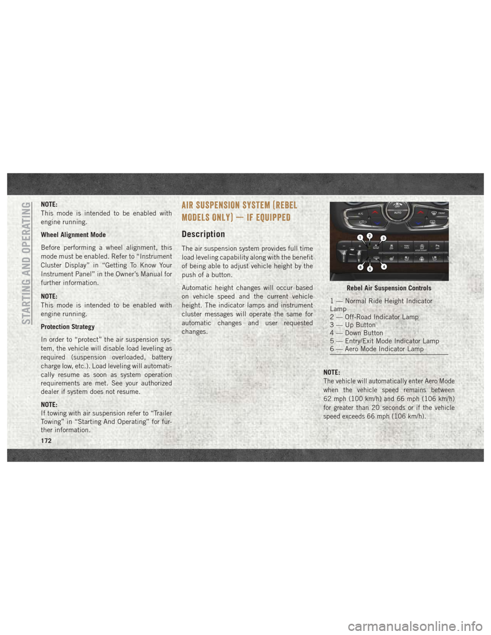
Rebel Air Suspension Controls
1 — Normal Ride Height Indicator
Lamp
2 — Off-Road Indicator Lamp
3 — Up Button
4 — Down Button
5 — Entry/Exit Mode Indicator Lamp
6 — Aero Mode Indicator Lamp
STARTING AND OPERATING
172
Page 176 of 372

to “Instrument Cluster Display” in “Getting
To Know Your Instrument Panel” in the Own-
er’s Manual for further information.
NOTE:
This mode is intended to be enabled with
engine running.
Tire/Jack Mode
To assist with changing a tire, the air suspen-
sion system has a feature which allows the
automatic leveling to be disabled. Refer to
“Instrument Cluster Display” in “Getting To
Know Your Instrument Panel” in the Owner’s
Manual for further information.
NOTE:
This mode is intended to be enabled with
engine running.
Transport Mode
For towing your vehicle with four wheels off
the ground, the air suspension system has a
feature which will put the vehicle into Entry/
Exit height and disable the automatic loadleveling system. Refer to “Instrument Cluster
Display” in “Getting To Know Your Instru-
ment Panel” in the Owner’s Manual for fur-
ther information.
NOTE:
This mode is intended to be enabled with
engine running.
Wheel Alignment Mode
Before performing a wheel alignment, this
mode must be enabled. Refer to “Instrument
Cluster Display” in “Getting To Know Your
Instrument Panel” in the Owner’s Manual for
further information.
NOTE:
This mode is intended to be enabled with
engine running.
Protection Strategy
In order to “protect” the air suspension sys-
tem, the vehicle will disable load leveling as
required (suspension overloaded, battery
charge low, etc.). Load leveling will automati-
cally resume as soon as system operation
requirements are met. See your authorized
dealer if system does not resume. NOTE:
If towing with air suspension refer to “Trailer
Towing” in “Starting And Operating” for fur-
ther information.
AIR SUSPENSION SYSTEM
(2500/3500 MODELS) — IF
EQUIPPED
Description
This air suspension system is a rear leveling
ride height system. The main purpose of this
system is to maintain the truck’s rear ride
height level. There are two selectable heights
that can be chosen based on your operating
conditions.
The system requires that the ignition be in
ON/RUN position or the engine running with
zero vehicle speed for all user requested
changes and load leveling.
STARTING AND OPERATING
174
Page 182 of 372

NOTE:
If the vehicle speed remains below 8 mph
(13 km/h), the Rear View Camera image will
be displayed continuously until deactivated
via the touchscreen button "X".
If equipped with a Cargo Camera, a touch-
screen button
to indicate the current
active Camera image being displayed is made
available whenever the Rear View Camera
image is displayed.
If equipped with a Cargo Camera, a touch-
screen button
to switch the display to
Cargo Camera image is made available when-
ever the Rear View Camera image is dis-
played.
A touchscreen button "X" to disable display of
the camera image is made available when the
vehicle is not in REVERSE gear.
When enabled, active guide lines are overlaid
on the image to illustrate the width of the
vehicle and its projected backup path based
on the steering wheel position. The active
guide lines will show separate zones that will
help indicate the distance to the rear of the
vehicle. NOTE:
For further information about how to access
and change the programmable features of the
ParkView Rear Backup Camera, refer to
“Uconnect Settings ” in “Multimedia” in the
Owner’s Manual for further information.
WARNING!
Drivers must be careful when backing up
even when using the ParkView Rear Back
Up Camera. Always check carefully behind
your vehicle, and be sure to check for
pedestrians, animals, other vehicles, ob-
structions, or blind spots before backing
up. You are responsible for the safety of
your surroundings and must continue to
pay attention while backing up. Failure to
do so can result in serious injury or death.
CAUTION!
• To avoid vehicle damage, ParkView
should only be used as a parking aid.
The ParkView camera is unable to view
every obstacle or object in your drive
path.
CAUTION!
• To avoid vehicle damage, the vehiclemust be driven slowly when using
ParkView to be able to stop in time when
an obstacle is seen. It is recommended
that the driver look frequently over his/
her shoulder when using ParkView.
NOTE:
If snow, ice, mud, or any foreign substance
builds up on the camera lens, clean the lens,
rinse with water, and dry with a soft cloth. Do
not cover the lens.
Turning Rear View Camera Image On:
1. Press the "Controls" button located on the bottom of the Uconnect display.
2. Press the "Backup Camera" button
to turn the Rear View Camera system on.
NOTE:
Once initiated by the "Backup Camera" but-
ton, the Rear View Camera image may be
deactivated by pressing the "X" button on the
touchscreen. On deactivation, the previous
selected screen will appear.
STARTING AND OPERATING
180
Page 196 of 372
2. Hook up the trailer and make the electri-cal connections according to the trailer
manufacturer's instructions.
3. When a trailer with electric/EOH brakes is plugged in, the trailer connected message
should appear in the instrument cluster
display (if the connection is not recog-
nized by the ITBM, braking functions will
not be available), the GAIN setting will
illuminate and the correct type of trailer
must be selected from the instrument
cluster display options. 4. Push the UP or DOWN button on the
steering wheel until “TRAILER TOW” ap-
pears on the screen.
5. Push the RIGHT arrow on the steering wheel to enter “TRAILER TOW”.
6. Push the UP or DOWN buttons until the Trailer Brake Type appears on the screen.
7. Push the RIGHT arrow and then push the UP or DOWN buttons until the proper
Trailer Brake Type appears on the screen.
8. In a traffic-free environment, tow the trailer on a dry, level surface at a speed of 20–25 mph (30–40 km/h) and squeeze
the manual brake control lever
completely.
9. If the trailer wheels lockup (indicated by squealing tires), reduce the GAIN setting;
if the trailer wheels turn freely, increase
the GAIN setting.
Repeat steps 8 and 9 until the GAIN setting
is at a point just below trailer wheel lockup. If
towing a heavier trailer, trailer wheel lockup
may not be attainable even with the maxi-
mum GAIN setting of 10.
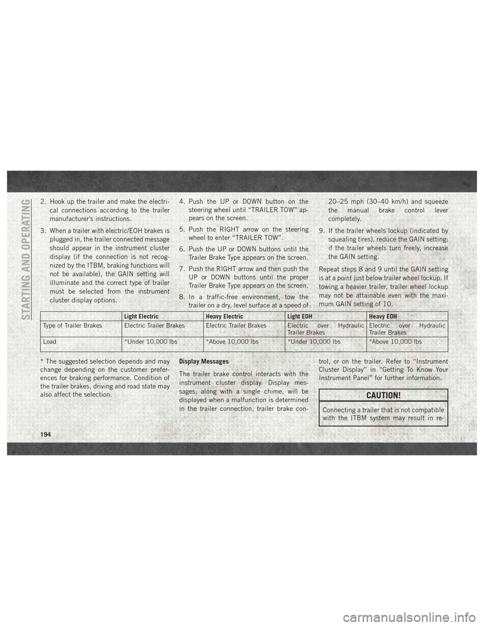
Light Electric Heavy ElectricLight EOHHeavy EOH
Type of Trailer Brakes Electric Trailer Brakes Electric Trailer Brakes Electric over Hydraulic Trailer BrakesElectric over Hydraulic
Trailer Brakes
Load *Under 10,000 lbs *Above 10,000 lbs *Under 10,000 lbs *Above 10,000 lbs
* The suggested selection depends and may
change depending on the customer prefer-
ences for braking performance. Condition of
the trailer brakes, driving and road state may
also affect the selection. Display Messages
The trailer brake control interacts with the
instrument cluster display. Display mes-
sages, along with a single chime, will be
displayed when a malfunction is determined
in the trailer connection, trailer brake con- trol, or on the trailer. Refer to “Instrument
Cluster Display” in “Getting To Know Your
Instrument Panel” for further information.
CAUTION!
Connecting a trailer that is not compatible
with the ITBM system may result in re-
STARTING AND OPERATING
194
Page 212 of 372

NOTE:
Always stow the spare tire with the valve stem
facing the ground. It is recommended that
you stow the flat or spare to avoid tangling the
loose cable.NOTE:
The winch mechanism is designed for use
with the extension tube only. Use of an air
wrench or other power tools is not recom-
mended and can damage the winch.
Preparations For Jacking
1. Park the vehicle on a firm, level surface.
Avoid ice or slippery areas.
WARNING!
Do not attempt to change a tire on the side
of the vehicle close to moving traffic, pull
far enough off the road to avoid being hit
when operating the jack or changing the
wheel.
2. Place the gear selector into PARK. On four-wheel drive vehicles, shift the trans-
fer case to the 4L position.
3. Turn on the Hazard Warning flasher.
4. Apply the parking brake.
5. Turn the ignition OFF. 6. Block both the front and rear of the wheel
diagonally opposite the jacking position.
For example, if the right front wheel is
being changed, block the left rear wheel.
NOTE:
Passengers should not remain in the vehicle
when the vehicle is being jacked.
Lug Wrench/Spare Tire
1 — Lug Wrench 2 — Spare Tire
Wheel Blocked
IN CASE OF EMERGENCY
210
Page 216 of 372
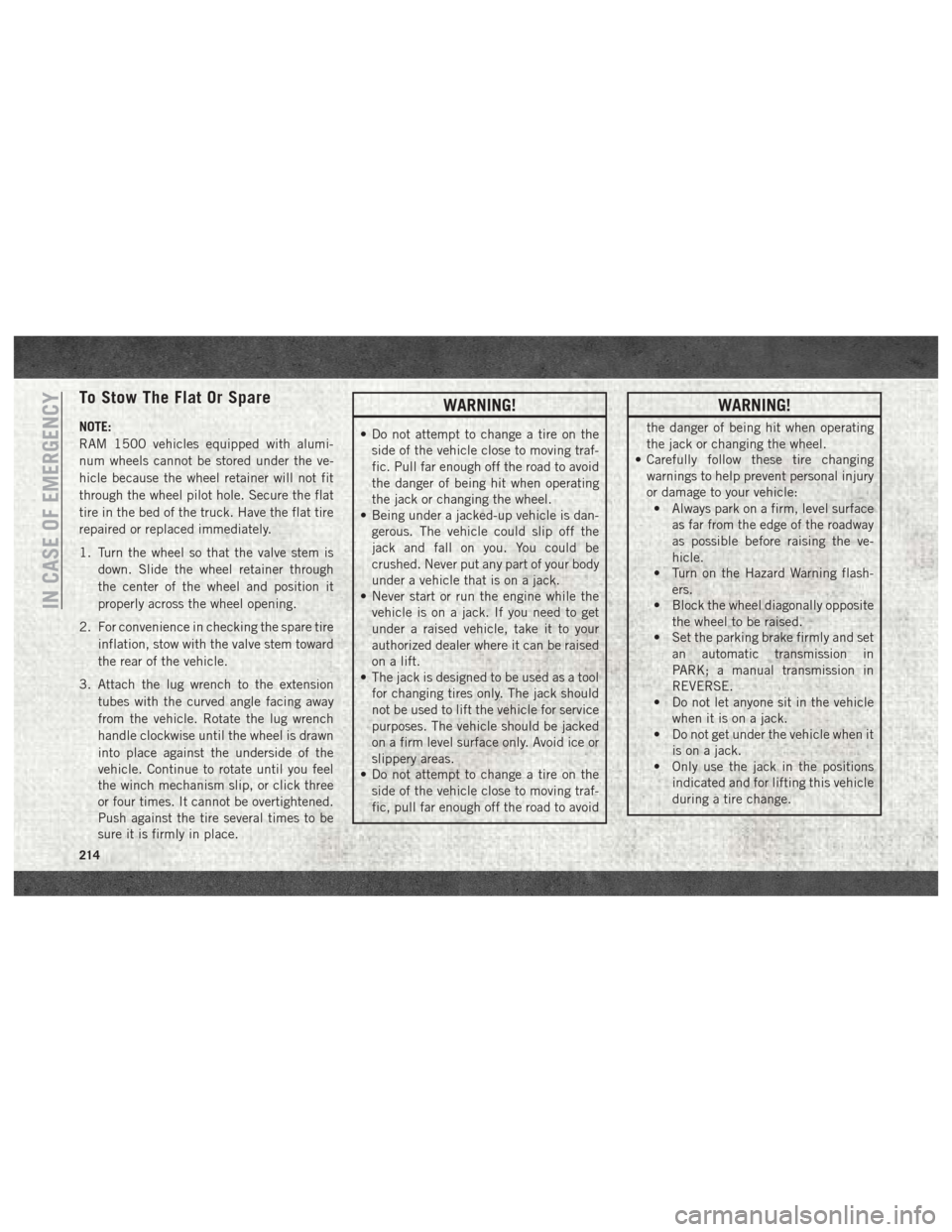
To Stow The Flat Or Spare
NOTE:
RAM 1500 vehicles equipped with alumi-
num wheels cannot be stored under the ve-
hicle because the wheel retainer will not fit
through the wheel pilot hole. Secure the flat
tire in the bed of the truck. Have the flat tire
repaired or replaced immediately.
1. Turn the wheel so that the valve stem isdown. Slide the wheel retainer through
the center of the wheel and position it
properly across the wheel opening.
2. For convenience in checking the spare tire inflation, stow with the valve stem toward
the rear of the vehicle.
3. Attach the lug wrench to the extension tubes with the curved angle facing away
from the vehicle. Rotate the lug wrench
handle clockwise until the wheel is drawn
into place against the underside of the
vehicle. Continue to rotate until you feel
the winch mechanism slip, or click three
or four times. It cannot be overtightened.
Push against the tire several times to be
sure it is firmly in place.
WARNING!
• Do not attempt to change a tire on theside of the vehicle close to moving traf-
fic. Pull far enough off the road to avoid
the danger of being hit when operating
the jack or changing the wheel.
• Being under a jacked-up vehicle is dan-
gerous. The vehicle could slip off the
jack and fall on you. You could be
crushed. Never put any part of your body
under a vehicle that is on a jack.
• Never start or run the engine while the
vehicle is on a jack. If you need to get
under a raised vehicle, take it to your
authorized dealer where it can be raised
on a lift.
• The jack is designed to be used as a tool
for changing tires only. The jack should
not be used to lift the vehicle for service
purposes. The vehicle should be jacked
on a firm level surface only. Avoid ice or
slippery areas.
• Do not attempt to change a tire on the
side of the vehicle close to moving traf-
fic, pull far enough off the road to avoid
WARNING!
the danger of being hit when operating
the jack or changing the wheel.
• Carefully follow these tire changing
warnings to help prevent personal injury
or damage to your vehicle:• Always park on a firm, level surface
as far from the edge of the roadway
as possible before raising the ve-
hicle.
• Turn on the Hazard Warning flash-
ers.
• Block the wheel diagonally opposite
the wheel to be raised.
• Set the parking brake firmly and set
an automatic transmission in
PARK; a manual transmission in
REVERSE.
• Do not let anyone sit in the vehicle
when it is on a jack.
• Do not get under the vehicle when it
is on a jack.
• Only use the jack in the positions
indicated and for lifting this vehicle
during a tire change.
IN CASE OF EMERGENCY
214
Page 231 of 372
SERVICING AND MAINTENANCE
SCHEDULED SERVICING —
GASOLINE ENGINE.............230
Maintenance Plan — Gasoline Engine. .231
Heavy Duty Use Of The Vehicle ......234
SCHEDULED SERVICING —
1500 3.0L DIESEL ENGINE........234
Maintenance Plan — Diesel Fuel Up To
B5 Biodiesel (1500 Diesel) ........235
Additional Maintenance — B6 To
B20 Biodiesel (1500 Diesel) .......237
SCHEDULED MAINTENANCE —
6.7L CUMMINS DIESEL ENGINE .....237
Oil Change Indicator System —
Cummins Diesel...............238
Perform Service Indicator —
Cummins Diesel ..............239
Maintenance Plan — Cummins Diesel
Engine .....................239
ENGINE COMPARTMENT .........243
3.6L Engine.................243
5.7L Engine .................244
6.4L Engine .................245
3.0L Diesel Engine .............246
6.7L Diesel Engine — Six-Speed 68RFE
(2500/3500 Models) ............247
6.7L Diesel Engine — Six-Speed AS69RC
HD (3500/Chassis Cab Models) .....248
DEALER SERVICE — 3.0L DIESEL . . . .249
Engine Air Cleaner Filter.........249
Draining Fuel/Water Separator Filter . .249
Underbody Mounted Fuel Filter
Replacement .................250
Priming If The Engine Has Run Out Of
Fuel ......................251
DEALER SERVICE — 6.7L DIESEL
ENGINE ................... .252
Engine Air Cleaner Filter.........252Draining Fuel/Water Separator Filter . .253
Engine Mounted Fuel Filter
Replacement
.................254
Underbody Mounted Fuel Filter
Replacement .................255
Priming If The Engine Has Run Out Of
Fuel ......................256
HOISTING ................. .257
TIRES .................... .257
Tire Safety Information..........257
Tires — General Information .......264
Tire Types ...................268
Spare Tires — If Equipped .........269
Wheel And Wheel Trim Care .......271
DEPARTMENT OF TRANSPORTATION
UNIFORM TIRE QUALITY GRADES . . . .272
Treadwear...................272
Traction Grades ...............273
Temperature Grades .............273
SERVICING AND MAINTENANCE
229
Page 242 of 372

Mileage or time passed (whichever comes first):7,500
15,000
22,500
30,000
37,500
45,000
52,500
60,000
67,500
75,000
82,500
90,000
97,500
105,000
112,500
120,000
127,500
135,000
142,500
150,000
Or Months: 6 12 18 24 30 36 42 48 54 60 66 72 78 84 90 96 102 108 114 120
Or Kilometers:
12,000
24,000
36,000
48,000
60,000
72,000
84,000
96,000
108,000
120,000
132,000
144,000
156,000
168,000
180,000
192,000
204,000
216,000
228,000
240,000
Inspect the front suspension, tie rod ends and
boot seals for cracks or leaks and all parts for
damage, wear, improper looseness or end
play; replace if necessary. XX XX X X XX X X
Inspect the brake linings. XXX XX X
Inspect and adjust parking brake. XXX XX X
Inspect drive belt; replace as necessary. XXX XX X
Inspect wheel bearings. XX XX X
Additional Maintenance
Replace cabin air filter. XXX XX X
Replace engine fuel filter element. X X X X X X X X X X
Replace chassis mounted fuel filter element. X X X X X X X X X X
Inspect the front and rear axle surfaces. If
gear oil leakage is suspected, check the fluid
level. If using your vehicle for police, taxi,
fleet, off-road or frequent trailer towing
change the axle fluid. *
Inspect the transfer case fluid (4x4), change
for any of the following: police, taxi, fleet, or
frequent trailer towing. XX XX X
Change the transfer case fluid (4x4). XX
SERVICING AND MAINTENANCE
240