key Ram 1500 2018 Owner's Manual
[x] Cancel search | Manufacturer: RAM, Model Year: 2018, Model line: 1500, Model: Ram 1500 2018Pages: 372, PDF Size: 7.1 MB
Page 56 of 372

WARNING!
• Your motorized door or gate will openand close while you are programming
the universal transceiver. Do not pro-
gram the transceiver if people or pets are
in the path of the door or gate.
• Do not run your vehicle in a closed
garage or confined area while program-
ming the transceiver. Exhaust gas from
your vehicle contains Carbon Monoxide
(CO) which is odorless and colorless.
Carbon Monoxide is poisonous when in-
haled and can cause you and others to
be severely injured or killed.
Programming HomeLink To A
Miscellaneous Device
Refer to “Programming HomeLink To A Ga-
rage Door Opener” for the procedure on how
to program HomeLink to a miscellaneous
device, as it follows the same procedure. Be
sure to determine if the device has a rolling
code, or non-rolling code before beginning
the programming process. NOTE:
Canadian radio frequency laws require trans-
mitter signals to time-out (or quit) after sev-
eral seconds of transmission, which may not
be long enough for HomeLink to pick up the
signal during programming. Similar to this
Canadian law, some U.S. gate operators are
designed to time-out in the same manner.
The procedure may need to be preformed
multiple times to successfully pair the device
to your HomeLink buttons.
Reprogramming A Single
HomeLink Button
To reprogram a single HomeLink button that
has been previously trained, without erasing
all the channels, follow the procedure below.
Be sure to determine whether the new device
you want to program the HomeLink button to
has a Rolling Code, or Non-rolling Code.
1. Cycle the ignition to the ON/RUN
position. NOTE:
For vehicle’s equipped with Keyless
Enter-N-Go, place the ignition in the RUN
position with the Engine ON. Make sure to
program HomeLink with the vehicle out-
side of the garage, or with the garage door
open at all times.
2. Push and hold the desired HomeLink but- ton until the instrument cluster display
shows the “CHANNEL # TRAINING”
message. Do not release the button.
3. Without releasing the button, proceed with
Step 2 in “Programming HomeLink To A
Garage Door Opener” and follow all re-
maining steps.
General Information
The following regulatory statement applies to
all Radio Frequency (RF) devices equipped in
this vehicle:
This device complies with Part 15 of the FCC
Rules and with Industry Canada license-
exempt RSS standard(s). Operation is sub-
ject to the following two conditions:
1. This device may not cause harmful inter- ference, andGETTING TO KNOW YOUR VEHICLE
54
Page 57 of 372
2. This device must accept any interferencereceived, including interference that may
cause undesired operation.
NOTE:
Changes or modifications not expressly ap-
proved by the party responsible for compli-
ance could void the user’s authority to oper-
ate the equipment.
INTERNAL EQUIPMENT
Electrical Power Outlets
The auxiliary 12 Volt (13 Amp) power outlets
can provide power for in-cab accessories de-
signed for use with the standard “cigar
lighter” plug. The 12 Volt power outlets and
USB Port (Charge Only) have a cap attached
to the outlet indicating “12V DC,” together
with either a key symbol, battery symbol, or
USB symbol. A key symbol indicates that the key must be
in the ON/RUN or ACC positions for the outlet
to provide power. The battery symbol indi-
cates that the outlet is connected to the
battery, and can provide power at all times.
NOTE:
To ensure proper operation, a Mopar knob
and element must be used.
CAUTION!
• Do not exceed the maximum power of
160 Watts (13 Amps) at 12 Volts. If the
160 Watts (13 Amps) power rating is
exceeded, the fuse protecting the sys-
tem will need to be replaced.
• Power outlets are designed for accessory
plugs only. Do not insert any other object
in the power outlets as this will damage
the outlet and blow the fuse. Improper
use of the power outlet can cause dam-
age not covered by your New Vehicle
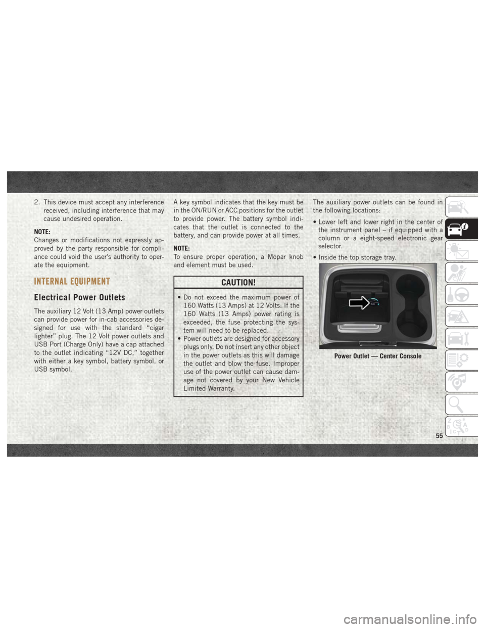
Limited Warranty. The auxiliary power outlets can be found in
the following locations:
• Lower left and lower right in the center of
the instrument panel – if equipped with a
column or a eight-speed electronic gear
selector.
• Inside the top storage tray.
Power Outlet — Center Console
55
Page 62 of 372
CAUTION!
Leaving the lid open for extended periods
of time could cause the vehicle battery to
discharge. If the lid is required to stay
open for extended periods of time, it is
recommended that the bin lights be
turned off manually using the on/off
switch.
The interior of the RamBox will automatically
illuminate when the lid is opened. In addition
to the automatic illumination switch, there is
a manual on/off switch located at the rear of
each storage bin. Pushing the switch once
will turn off the bin lights, pushing the switch
again will turn the lights back on.
Cargo bins feature two removable drain plugs
(to allow water to drain from bins). To remove
plug, pull up on the edge. To install push plug
downward into drain hole.
NOTE:
Provisions are provided in the bins for cargo
dividers and shelf supports. These accesso-
ries (in addition to other RamBox accesso-
ries) are available from Mopar.
Locking And Unlocking RamBox
Push and release the lock or unlock button on
the key fob to lock and unlock all doors, the
tailgate and the RamBox (if equipped). Refer
to “Keys” in “Getting To Know Your Vehicle”
in the Owner’s Manual for further details. The
RamBox storage bins can be locked using the
vehicle key. To lock and unlock the storage
bin, insert the key into the keyhole on the
push button and turn clockwise to lock or
counterclockwise to unlock. Always return
the key to the upright (vertical) position be-
fore removing the key from the push button.
CAUTION!
• Ensure cargo bin lids are closed and latched before moving or driving vehicle.
• Loads applied to the top of the bin lid
should be minimized to prevent damage
to the lid and latching/hinging mecha-
nisms.
• Damage to the RamBox bin may occur
due to heavy/sharp objects placed in bin
that shift due to vehicle motion. In order
to minimize potential for damage, se-
CAUTION!
cure all cargo to prevent movement and
protect inside surfaces of bin from
heavy/sharp objects with appropriate
padding.
RamBox Safety Warning
Carefully follow these warnings to help pre-
vent personal injury or damage to your
vehicle:
WARNING!
• Always close the storage bin coverswhen your vehicle is unattended.
• Do not allow children to have access to
the storage bins. Once in the storage
bin, young children may not be able to
escape. If trapped in the storage bin,
children can die from suffocation or heat
stroke.
• In an accident, serious injury could re-
sult if the storage bin covers are not
properly latched.
GETTING TO KNOW YOUR VEHICLE
60
Page 63 of 372

WARNING!
• Do not drive the vehicle with the storagebin covers open.
• Keep the storage bin covers closed and
latched while the vehicle is in motion.
• Do not use a storage bin latch as a tie
down.
RamBox Storage Bin Cover Emergency Re-
lease Lever — If Equipped
As a security measure, a Storage Bin Cover
Emergency Release is built into the storage
bin cover latching mechanism.
NOTE:
In the event of an individual being locked
inside the storage bin, the storage bin cover
can be opened from inside of the bin by
pulling on the glow-in-the-dark lever at-
tached to the storage bin cover latching
mechanism.
Bed Extender — If Equipped
The bed extender has three functional posi-
tions:
• Storage Position • Divider Position
• Extender Position
Storage Position
The storage position for the bed extender is at
the front of the truck bed which maximizes
the bed cargo area when not in use.
To install the bed extender into the storage
position, perform the following:
1. Make sure the center handle is unlocked
using the vehicle key and rotate the center
handle vertically to release the extender
side gates.
2. With the side gates open, position the extender fully forward in the bed against
the front panel.
3. Rotate the side gates closed allowing the outboard ends to be positioned in front of
the cargo tie down loops.
4. Rotate the center handle horizontally to secure the side gates in the closed
position.
5. Lock the center handle using the vehicle key to secure the panel into place.
Divider Position
The divider position is intended for managing
your cargo and assisting in keeping cargo
from moving around the bed. There are 11 di-
vider slots along the bed inner panels which
allow for various positions to assist in manag-
ing your cargo.
To install the bed extender into a divider
position, perform the following:
1. Make sure the center handle is unlocked
using the vehicle key and rotate the center
handle vertically to release the extender
side gates.
2. With the side gates open, position the extender so the outboard ends align with
the intended slots in the sides of the bed.
3. Rotate the side gates closed so that the outboard ends are secured into the in-
tended slots of the bed.
4. Rotate the center handle horizontally to secure the side gates in the closed
position.
5. Lock the center handle to secure the panel into place.
61
Page 65 of 372
EASY-OFF TAILGATE
To simplify mounting of a camper unit with an
overhang, the tailgate can be removed.
NOTE:
If your vehicle is equipped with a rear camera
or Remote Keyless Entry, the electrical con-
nector must be disconnected prior to remov-
ing the tailgate.
Removing The Tailgate
1. Disconnect the wiring harness for the rearcamera or Remote Keyless Entry (if
equipped).
2. Unlatch the tailgate and remove the sup- port cables by releasing the lock tang from
the pivot. 3. Raise the right side of the tailgate until
the right side pivot clears the hanger
bracket.
4. Slide the entire tailgate to the right to free the left side pivot.
5. Remove the tailgate from the vehicle.
NOTE:
Do not carry the tailgate loose in the truck
pickup box.Locking Tailgate
The lock is located next to the tailgate
handle. The tailgate can be locked using the
vehicle key or by locking the truck with the
key fob if equipped with remote keyless entry.
TRI-FOLD TONNEAU COVER
The Tonneau Cover can be removed and rein-
stalled by using the locking clamps located
underneath the Tonneau Cover. Refer to the
Owner’s Manual for further information.
NOTE:
Be sure that the Tonneau Cover is secured
before driving.
63
Page 77 of 372
Instrument Cluster Display Programmable Features
The instrument cluster display can be used to view or change the following settings. Push theupordown arrow button until System Setup
displays, then push the rightarrow button. Scroll through the settings using the upordown arrow button. Push the rightarrow button to change
the setting. Push the leftarrow button to scroll back to a previous menu or sub menu.
• Language Select • Remote Start Comfort System
• Units • Easy Exit Seat
• ParkSense • Key Off Power Delay
• Tilt Mirror In Reverse • Commercial Settings
• Rain Sensing Wipers • Air Suspension Display Alerts
• Hill Start Assist • Aero Ride Height Mode
• Headlights Off Delay • Tire/Jack Mode
• Illuminated Approach • Transport Mode
• Headlights On With Wipers • Wheel Alignment Mode
• Automatic Highbeams • Horn With Remote Lower
• Flash Lights With Lock • Lights With Remote Lower
• Auto Lock Doors • Trailer Select
• Auto Unlock Doors • Brake Type
• Sound Horn With Remote Start • Trailer Name
• Sound Horn With Remote Lock • Compass Variance
• Remote Unlock Sequence • Calibrate Compass
• Key Fob Linked To Memory • Fuel Saver Display
• Passive Entry • Park Assist Front Chime Volume
• Park Assist Rear Chime Volume
75
Page 138 of 372
WARNING!
• ONLY use the driver’s side floor mat onthe driver’s side floor area. To check for
interference, with the vehicle properly
parked with the engine off, fully depress
the accelerator, the brake, and the
clutch pedal (if present) to check for
interference. If your floor mat interferes
with the operation of any pedal, or is not
secure to the floor, remove the floor mat
from the vehicle and place the floor mat
in your trunk.
• ONLY use the passenger’s side floor mat
on the passenger’s side floor area.
• ALWAYS make sure objects cannot fall or
slide into the driver’s side floor area
when the vehicle is moving. Objects can
become trapped under accelerator,
brake, or clutch pedals and could cause
a loss of vehicle control.
•
NEVER place any objects under the floor
mat (e.g., towels, keys, etc.). These ob-
jects could change the position of the
floor mat and may cause interference with
the accelerator, brake, or clutch pedals.
WARNING!
• If the vehicle carpet has been removed
and re-installed, always properly attach
carpet to the floor and check the floor
mat fasteners are secure to the vehicle
carpet. Fully depress each pedal to
check for interference with the accelera-
tor, brake, or clutch pedals then re-
install the floor mats.
• It is recommended to only use mild soap
and water to clean your floor mats. After
cleaning, always check your floor mat
has been properly installed and is se-
cured to your vehicle using the floor mat
fasteners by lightly pulling mat.
Periodic Safety Checks You
Should Make Outside The Vehicle
Tires
Examine tires for excessive tread wear and
uneven wear patterns. Check for stones,
nails, glass, or other objects lodged in the
tread or sidewall. Inspect the tread for cuts and cracks. Inspect sidewalls for cuts,
cracks, and bulges. Check the wheel bolts for
tightness. Check the tires (including spare)
for proper cold inflation pressure.
Lights
Have someone observe the operation of brake
lights and exterior lights while you work the
controls. Check turn signal and high beam
indicator lights on the instrument panel.
Door Latches
Check for proper closing, latching, and lock-
ing.
Fluid Leaks
Check area under the vehicle after overnight
parking for fuel, coolant, oil, or other fluid
leaks. Also, if gasoline fumes are detected or
if fuel, or brake fluid leaks are suspected. The
cause should be located and corrected imme-
diately.
SAFETY
136
Page 139 of 372
STARTING AND OPERATING
STARTING THE ENGINE —
GASOLINE ENGINE.............139
Normal Starting Using ENGINE
START/STOP Button ............139
STARTING THE ENGINE —
3.0L DIESEL ENGINE............142
Normal Starting Using ENGINE
STOP/START Button ............142
Extreme Cold Weather ...........145
STARTING THE ENGINE — 6.7L DIESEL
ENGINE................... .146
Keyless Enter-N-Go — Ignition ......146
Extreme Cold Weather ...........148
NORMAL OPERATION — 3.0L DIESEL
ENGINE................... .149
Cold Weather Precautions.........149
Stopping The Engine ............150
NORMAL OPERATION — 6.7L DIESEL
ENGINE................... .151
Cold Weather Precautions.........151
Engine Idling ................151
Stopping The Engine ............152
ENGINE BREAK-IN RECOMMENDATIONS —
GASOLINE ENGINE.............153
ENGINE BREAK-IN RECOMMENDATIONS —
3.0L DIESEL ................ .154
ENGINE BREAK-IN RECOMMENDATIONS —
6.7L DIESEL ................ .154
AUTOMATIC TRANSMISSION ......155
Key Ignition Park Interlock........156
Brake/Transmission Shift Interlock
System ....................156
Eight-Speed Automatic Transmission —
If Equipped .................156
Six-Speed Automatic Transmission —
1500 Models Only (If Equipped) .....158
Six-Speed Automatic Transmission —
2500/3500 Models Only .........160
FOUR-WHEEL DRIVE OPERATION —
IF EQUIPPED............... .162
Electronically Shifted Transfer Case
(Four-Position Switch) — If Equipped .162
Electronically Shifted Transfer Case
(Five-Position Switch) — If Equipped .164 Four-Position Electronically Shifted Transfer
Case (Eight Speed Transmission Only) —
If Equipped
..................166
Five-Position Electronically Shifted Transfer
Case (Eight Speed Transmission Only) —
If Equipped ..................168
AIR SUSPENSION SYSTEM
(1500 MODELS) — IF EQUIPPED . . . .170
Description..................170
Air Suspension Modes ...........171
AIR SUSPENSION SYSTEM (REBEL
MODELS ONLY) — IF EQUIPPED . . . .172
Description..................172
Air Suspension Modes ...........173
AIR SUSPENSION SYSTEM (2500/
3500 MODELS) — IF EQUIPPED .....174
Description..................174
Air Suspension Modes ...........175
SPEED CONTROL..............176
To Activate..................177
To Set A Desired Speed ..........177
To Vary The Speed Setting .........177
STARTING AND OPERATING
137
Page 141 of 372
STARTING THE ENGINE — GASOLINE
ENGINE
Before starting your vehicle, adjust your seat,
adjust both inside and outside mirrors, and
fasten your seat belt.
The starter should not be operated for more
than 10-second intervals. Waiting a few sec-
onds between such intervals will protect the
starter from overheating.
WARNING!
• When leaving the vehicle, always makesure the keyless ignition node is in the
"OFF" mode, remove the key fob from the
vehicle and lock the vehicle.
• Never leave children alone in a vehicle,
or with access to an unlocked vehicle.
Allowing children to be in a vehicle un-
attended is dangerous for a number of
reasons. A child or others could be seri-
ously or fatally injured. Children should
be warned not to touch the parking
brake, brake pedal or the gear selector.
WARNING!
• Do not leave the key fob in or near thevehicle, or in a location accessible to
children, and do not leave the ignition of
a vehicle equipped with Keyless Enter-
N-Go in the ACC or ON/RUN mode. A
child could operate power windows,
other controls, or move the vehicle.
• Do not leave children or animals inside
parked vehicles in hot weather. Interior
heat build-up may cause serious injury
or death.
Normal Starting Using ENGINE
START/STOP Button
To Turn On The Engine Using The ENGINE START/
STOP Button
1. The transmission must be in PARK.
2. Press and hold the brake pedal while pushing the ENGINE START/STOP button
once.
3. The system takes over and attempts to start the vehicle. If the vehicle fails to
start, the starter will disengage automati-
cally after 10 seconds. 4. If you wish to stop the cranking of the
engine prior to the engine starting, push
the button again.
NOTE:
Normal starting of either a cold or a warm
engine is obtained without pumping or press-
ing the accelerator pedal.
To Turn Off The Engine Using ENGINE START/
STOP Button
1. Place the gear selector in PARK, then push and release the ENGINE START/
STOP button.
2. The ignition will return to the OFF mode.
3. If the gear selector is not in PARK, the ENGINE START/STOP button must be
held for two seconds or three short pushes
in a row with the vehicle speed above
5 MPH (8 km/h) before the engine will
shut off. The ignition will remain in the
ACC mode until the gear selector is in
PARK and the button is pushed twice to
the OFF mode.
4. If the gear selector is not in PARK and the ENGINE START/STOP button is pushed
once with the vehicle speed above 5 MPH
139
Page 143 of 372
• Ignition switched from RUN to ACC
NOTE:
For Keyless Go equipped vehicles, The en-
gine will turn off and the ignition switch will
change to ACC mode. After 30 minutes the
ignition switches to OFF automatically, un-
less the driver turns the ignition switch OFF.
If the vehicle is not in PARK and the driver exits
the vehicle with the engine running, the vehicle
may AutoPark.
AutoPark will engage when all of these con-
ditions are met:
• Vehicle is equipped with a rotary shifter andan 8-speed transmission
• Vehicle is not in PARK
• Vehicle speed is 1.2 MPH (1.9 km/h) or less
• Driver’s seat belt is unbuckled
• Driver’s door is ajar
• Brake Pedal is not depressed
The MESSAGE “AutoPark Engaged Shift to P
then Shift to Gear” will display in the instru-
ment cluster. NOTE:
In some cases the ParkSense graphic will be
displayed in the instrument cluster, causing
the “AutoPark Engaged Shift to P then Shift to
Gear” to not be seen. In these cases, the
shifter must be returned to “P” to select
desired gear.
If the driver shifts into PARK while moving, the
vehicle may AutoPark.
AutoPark will engage
ONLYwhen vehicle
speed is 1.2 MPH (1.9 km/h) or less.
The MESSAGE “Vehicle Speed is Too High to
Shift to P”will be displayed in the instrument
cluster if vehicle speed is above 1.2 MPH
(1.9 km/h).
WARNING!
If vehicle speed is above 1.2 MPH
(1.9 km/h), the transmission will default to
NEUTRAL until the vehicle speed drops
below 1.2 MPH (1.9 km). A vehicle left in
the NEUTRAL position can roll. As an
added precaution, always apply the park-
ing brake when exiting the vehicle. 4WD LOW — If Equipped
AutoPark will be disabled when operating the
vehicle in 4WD LOW.
The MESSAGE “AutoPark Disabled” will be
displayed in the instrument cluster.
Additional customer warnings will be given
when all of these conditions are met:
• Vehicle is not in PARK
• Driver’s Door is ajar
• Vehicle is in 4WD LOW range
The MESSAGE “AutoPark Not Engaged” will
be displayed in the instrument cluster. A
warning chime will continue until you shift
the vehicle into PARK or the Driver’s Door is
closed.
ALWAYS DO A VISUAL CHECK that your vehicle
is in PARK by looking for the "P" in the
Instrument Cluster Display and near the
shifter. As an added precaution, always apply
the parking brake when exiting the vehicle.
141