tow mode Ram 1500 2018 User Guide
[x] Cancel search | Manufacturer: RAM, Model Year: 2018, Model line: 1500, Model: Ram 1500 2018Pages: 372, PDF Size: 7.1 MB
Page 11 of 372
GETTING TO KNOW YOUR VEHICLE
VEHICLE USER GUIDE — IF EQUIPPED .11
KEYS......................13
Key Fobs ....................13
IGNITION SWITCH ..............17
Wireless Ignition Node (WIN) — If
Equipped....................17
Keyless Push Button Ignition — If
Equipped ....................17
REMOTE START — IF EQUIPPED .....17
To Enter Remote Start Mode........17
To Exit Remote Start Mode Without
Driving The Vehicle .............18
To Exit Remote Start Mode And Drive
The Vehicle ...................18
General Information .............18
VEHICLE SECURITY ALARM ........18
To Arm The System..............18
To Disarm The System ............19
DOORS.....................19
Keyless Enter-N-Go — Passive Entry . . .19
SEATS .....................22
Driver Memory Seat — If Equipped ....22
Heated Seats ..................25
HEAD RESTRAINTS ..............27
Front Head Restraint Adjustment .....27
Rear Head Restraint Adjustment ......28
Front Head Restraint Removal .......28
Rear Head Restraint Removal ........28
STEERING WHEEL..............29
Tilt Steering Column .............29
Heated Steering Wheel — If Equipped . .29
DRIVER ADJUSTABLE PEDALS — IF
EQUIPPED ...................30
MIRRORS ...................31
Power Folding Outside Mirrors For Standard
And Trailer Tow — If Equipped .......31
EXTERIOR LIGHTS..............32
Headlight Switch...............32
Headlights ...................32
Multifunction Lever .............32
High/Low Beam Switch ...........32Automatic High Beam Headlamp Control —
If Equipped
..................33
Automatic Headlights — If Equipped . .33
Parking Lights And Panel Lights ......33
Turn Signals ..................33
Lane Change Assist — If Equipped ....34
Cargo Light With Bed Lights —
If Equipped ..................34
WINDSHIELD WIPERS AND WASHERS .35
Windshield Wipers ..............35
CLIMATE CONTROLS .............36
Manual Climate Controls With A
Touchscreen..................36
Automatic Climate Controls With A
Touchscreen ..................41
Climate Control Functions ..........46
Automatic Temperature Control (ATC) —
If Equipped ...................47
Operating Tips .................48
POWER SUNROOF — IF EQUIPPED ....49
Opening Sunroof...............49
Closing Sunroof ................49
GETTING TO KNOW YOUR VEHICLE
9
Page 31 of 372
STEERING WHEEL
Tilt Steering Column
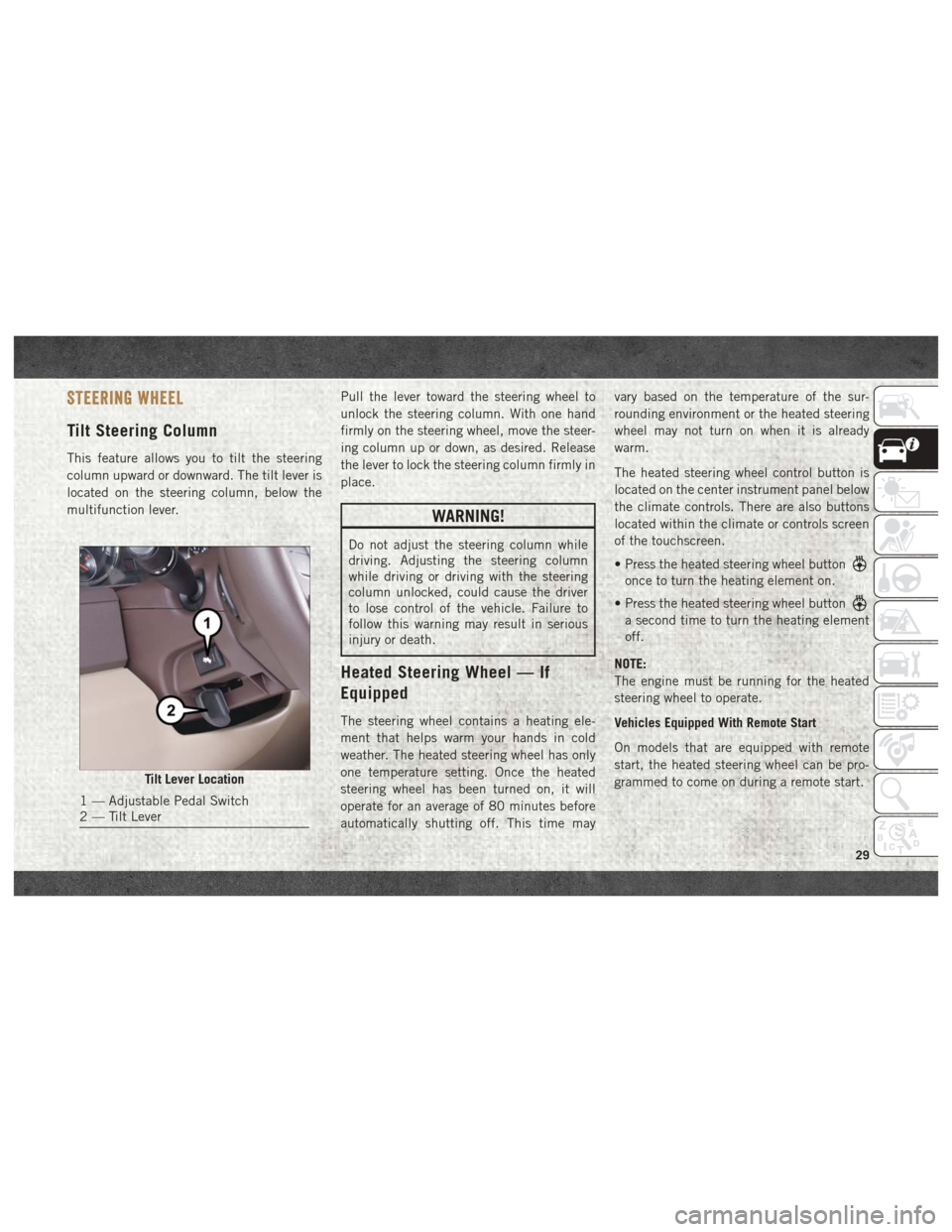
This feature allows you to tilt the steering
column upward or downward. The tilt lever is
located on the steering column, below the
multifunction lever.Pull the lever toward the steering wheel to
unlock the steering column. With one hand
firmly on the steering wheel, move the steer-
ing column up or down, as desired. Release
the lever to lock the steering column firmly in
place.
WARNING!
Do not adjust the steering column while
driving. Adjusting the steering column
while driving or driving with the steering
column unlocked, could cause the driver
to lose control of the vehicle. Failure to
follow this warning may result in serious
injury or death.
Heated Steering Wheel — If
Equipped
The steering wheel contains a heating ele-
ment that helps warm your hands in cold
weather. The heated steering wheel has only
one temperature setting. Once the heated
steering wheel has been turned on, it will
operate for an average of 80 minutes before
automatically shutting off. This time mayvary based on the temperature of the sur-
rounding environment or the heated steering
wheel may not turn on when it is already
warm.
The heated steering wheel control button is
located on the center instrument panel below
the climate controls. There are also buttons
located within the climate or controls screen
of the touchscreen.
• Press the heated steering wheel button
once to turn the heating element on.
• Press the heated steering wheel button
a second time to turn the heating element
off.
NOTE:
The engine must be running for the heated
steering wheel to operate.
Vehicles Equipped With Remote Start
On models that are equipped with remote
start, the heated steering wheel can be pro-
grammed to come on during a remote start.
Tilt Lever Location
1 — Adjustable Pedal Switch
2 — Tilt Lever
29
Page 33 of 372

CAUTION!
trols. Pedal travel may become limited if
movement is stopped by an obstruction in
the adjustable pedal's path.
MIRRORS
Power Folding Outside Mirrors For
Standard And Trailer Tow — If
Equipped
If equipped with power folding mirrors, they
can be electrically folded rearward and un-
folded into the drive position.
The switch for the power folding mirrors is
located between the power mirror switches L
(left) and R (right). Push the switch once and
the mirrors will fold in, push the switch a
second time and the mirrors will return to the
normal driving position.
If the mirror is manually folded after electri-
cally cycled, a potential extra button push is
required to get the mirrors back to the homeposition. If the mirror does not electrically
fold, check for ice or dirt build up at the pivot
area which can cause excessive drag.
Resetting The Power Folding Outside Mirrors
You may need to reset the power folding
mirrors if the following occurs:
• The mirrors are accidentally blocked while
folding.
• The mirrors are accidentally manually folded/unfolded. • The mirrors come out of the unfolded posi-
tion.
• The mirrors shake and vibrate at normal driving speeds.
To Reset The Power Folding Mirrors:
1. Using the power folding mirror switch, move the mirror to its full forward
position.
2. Using the power folding mirror switch, move the mirror to the full retract position
(this may require multiple button
pushes). This resets them to their normal
position.
NOTE:
• The power fold mirrors are designed to operate while the vehicle is stationary or
traveling at moderate speeds. If you at-
tempt to power fold the mirrors at high
speeds they may not fully open or close. You
should slow down to a moderate speed and
complete the operation.
• When pushing the power fold button 10 or more times in one minute the system shuts
down for one minute to protect the motors
from over heating.
Power Folding Mirror Switch
31
Page 46 of 372

IconDescription
Front Defrost Button
Press and release the touchscreen button, or push and release the button on the faceplate, to change the current airflow
setting to Defrost mode. The indicator illuminates when this feature is on. Air comes from the windshield and side win-
dow demist outlets. When the defrost button is selected, the blower level may increase. Use Defrost mode with maxi-
mum temperature settings for best windshield and side window defrosting and defogging. When toggling the front de-
frost mode button, the climate system will return to previous setting.
Rear Defrost Button
Push and release the button on the touchscreen, or push and release the button on the faceplate, to turn on the rear
window defroster and the heated outside mirrors (if equipped). An indicator will illuminate when the rear window de-
froster is on. The rear window defroster automatically turns off after ten minutes.
Uconnect 3
Uconnect 4C/4C NAV
Driver and Passenger Temperature Up and Down Buttons
Provides the driver and passenger with independent temperature control. Push the up arrow button on the faceplate,
press the up arrow button on the touchscreen, or press and slide the temperature bar towards the red arrow button on
the touchscreen for warmer temperature settings. Push the down arrow button on the faceplate, press the down arrow
button on the touchscreen, or press and slide the temperature bar towards the blue arrow button on the touchscreen for
cooler temperature settings. When the SYNC feature is active, the passenger’s temperature will move up and down with
the driver’s temperature, when it is increased and decreased, respectively.
NOTE:
Temperature numbers will only be displayed if the system is equipped with Automatic Temperature Control.
GETTING TO KNOW YOUR VEHICLE
44
Page 68 of 372
INSTRUMENT CLUSTER DISPLAY
Your vehicle may be equipped with an instru-
ment cluster display, which offers useful in-
formation to the driver. With the ignition in
the STOP/OFF mode, opening/closing of a
door will activate the display for viewing, and
display the total miles, or kilometers, in the
odometer. Your instrument cluster display is
designed to display important information
about your vehicle’s systems and features.
Using a driver interactive display located on
the instrument panel, your instrument clus-
ter display can show you how systems are
working and give you warnings when they are
not. The steering wheel mounted controls
allow you to scroll through the main menus
and submenus. You can access the specific
information you want and make selections
and adjustments.
Instrument Cluster Display
Controls
The instrument cluster display features a
driver-interactive display that is located in
the instrument cluster.
The instrument cluster display menu items
may consist of the following:
• Speedometer
• Vehicle Info
• Fuel Economy Info
• Trip A
• Trip B
• Audio
• Trailer Tow
• Stored Messages
• Screen Setup
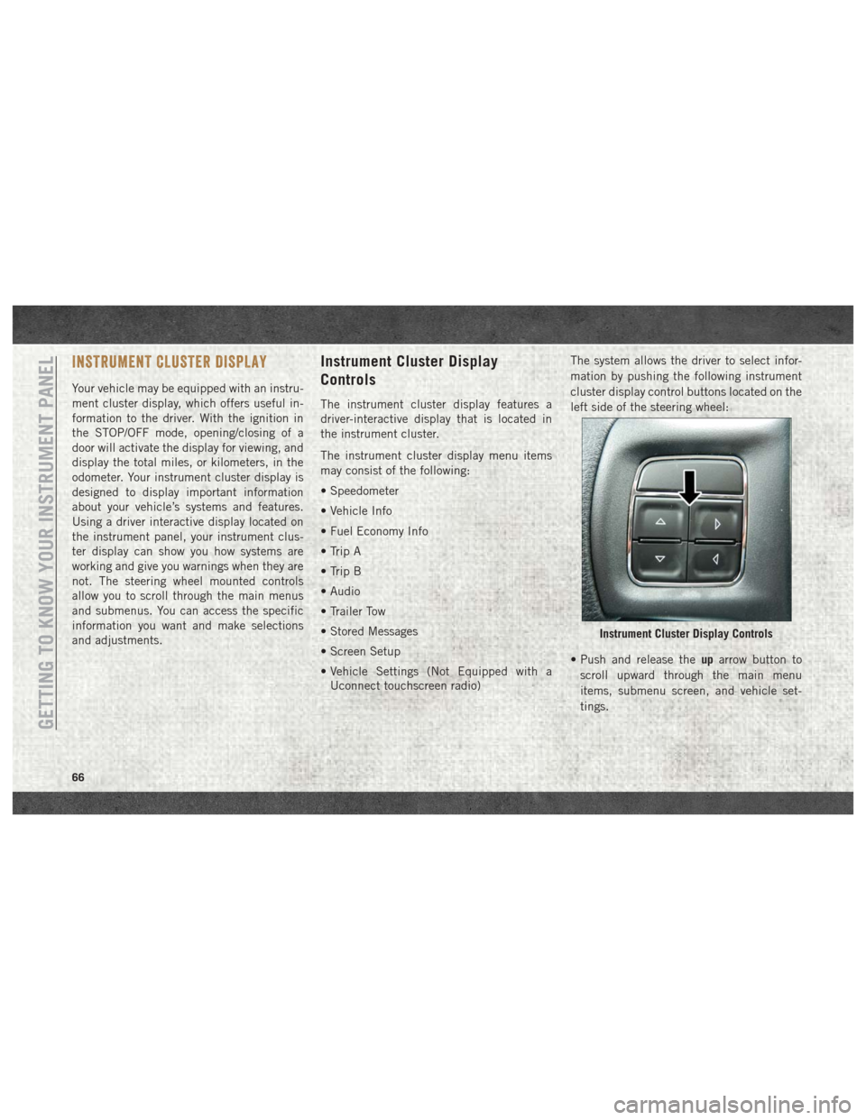
• Vehicle Settings (Not Equipped with aUconnect touchscreen radio) The system allows the driver to select infor-
mation by pushing the following instrument
cluster display control buttons located on the
left side of the steering wheel:
• Push and release the
uparrow button to
scroll upward through the main menu
items, submenu screen, and vehicle set-
tings.
Instrument Cluster Display Controls
GETTING TO KNOW YOUR INSTRUMENT PANEL
66
Page 84 of 372
CAUTION!
Continuous driving with the Transmission
Temperature Warning Light illuminated
will eventually cause severe transmission
damage or transmission failure.
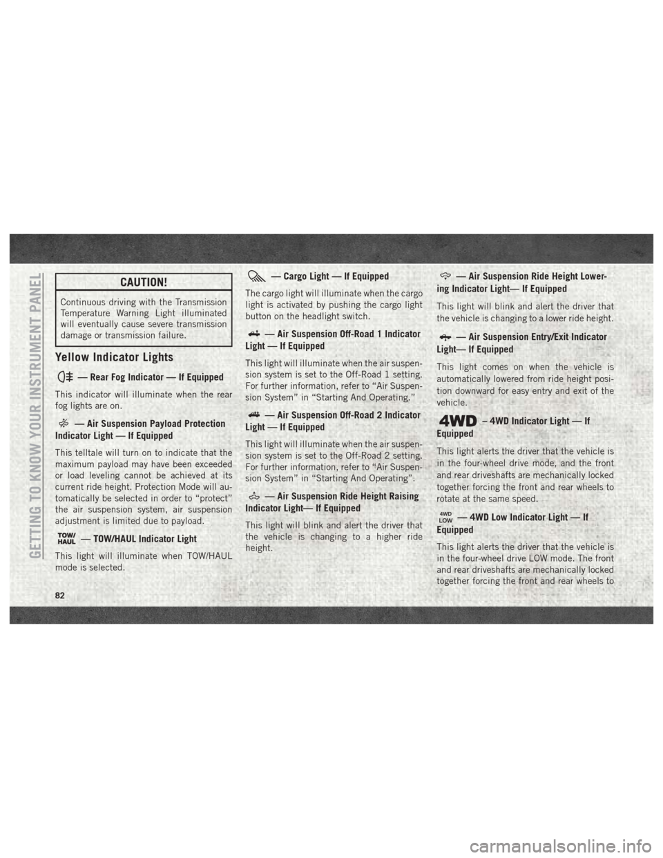
Yellow Indicator Lights
— Rear Fog Indicator — If Equipped
This indicator will illuminate when the rear
fog lights are on.
— Air Suspension Payload Protection
Indicator Light — If Equipped
This telltale will turn on to indicate that the
maximum payload may have been exceeded
or load leveling cannot be achieved at its
current ride height. Protection Mode will au-
tomatically be selected in order to “protect”
the air suspension system, air suspension
adjustment is limited due to payload.
— TOW/HAUL Indicator Light
This light will illuminate when TOW/HAUL
mode is selected.
— Cargo Light — If Equipped
The cargo light will illuminate when the cargo
light is activated by pushing the cargo light
button on the headlight switch.
— Air Suspension Off-Road 1 Indicator
Light — If Equipped
This light will illuminate when the air suspen-
sion system is set to the Off-Road 1 setting.
For further information, refer to “Air Suspen-
sion System” in “Starting And Operating.”
— Air Suspension Off-Road 2 Indicator
Light — If Equipped
This light will illuminate when the air suspen-
sion system is set to the Off-Road 2 setting.
For further information, refer to “Air Suspen-
sion System” in “Starting And Operating”.
— Air Suspension Ride Height Raising
Indicator Light— If Equipped
This light will blink and alert the driver that
the vehicle is changing to a higher ride
height.
— Air Suspension Ride Height Lower-
ing Indicator Light— If Equipped
This light will blink and alert the driver that
the vehicle is changing to a lower ride height.
— Air Suspension Entry/Exit Indicator
Light— If Equipped
This light comes on when the vehicle is
automatically lowered from ride height posi-
tion downward for easy entry and exit of the
vehicle.
– 4WD Indicator Light — If
Equipped
This light alerts the driver that the vehicle is
in the four-wheel drive mode, and the front
and rear driveshafts are mechanically locked
together forcing the front and rear wheels to
rotate at the same speed.
— 4WD Low Indicator Light — If
Equipped
This light alerts the driver that the vehicle is
in the four-wheel drive LOW mode. The front
and rear driveshafts are mechanically locked
together forcing the front and rear wheels toGETTING TO KNOW YOUR INSTRUMENT PANEL
82
Page 86 of 372
– 4WD AUTO Indicator Light — If
Equipped
This light alerts the driver that the vehicle is
in the four-wheel drive auto mode, and the
front axle is engaged, but the vehicle's power
is sent to the rear wheels. Four-wheel drive
will be automatically engaged when the ve-
hicle senses a loss of traction.
For further information on four-wheel drive
operation and proper use, refer to “Four-
Wheel Drive Operation — If Equipped” in
“Starting And Operating.”
White Indicator Lights
— Cruise Control Ready Indicator
This light will turn on when the speed control
is ready, but not set.
— Speed Control SET Indicator Light
— If Equipped
This light will turn on when the speed control
is set. Refer to “Speed Control — If
Equipped” in “Starting And Operating” for
further information.
— Hill Descent Control (HDC) Indicator
Light — If Equipped
This indicator shows when the Hill Descent
Control (HDC) feature is turned on. The lamp
will be on solid when HDC is armed. HDC can
only be armed when the transfer case is in the
“4WD LOW” position and the vehicle speed
is less then 30 mph (48 km/h). If these
conditions are not met while attempting to
use the HDC feature, the HDC indicator light
will flash on/off.
Blue Indicator Lights
— High Beam Indicator Light
This indicator shows that the high beam
headlights are on. With the low beams acti-
vated, push the multifunction lever forward
(toward the front of the vehicle) to turn on the
high beams. Pull the multifunction lever rear-
ward (toward the rear of the vehicle) to turn
off the high beams. If the high beams are off,
pull the lever toward you for a temporary high
beam on, "flash to pass" scenario.
ONBOARD DIAGNOSTIC SYSTEM —
OBD II
Your vehicle is equipped with a sophisticated
Onboard Diagnostic system called OBD II.
This system monitors the performance of the
emissions, engine, and transmission control
systems. When these systems are operating
properly, your vehicle will provide excellent
performance and fuel economy, as well as
engine emissions well within current govern-
ment regulations.
If any of these systems require service, the
OBD II system will turn on the Malfunction
Indicator Light (MIL). It will also store diag-
nostic codes and other information to assist
your service technician in making repairs.
Although your vehicle will usually be drivable
and not need towing, see your authorized
dealer for service as soon as possible.
CAUTION!
• Prolonged driving with the MIL on could
cause further damage to the emission
control system. It could also affect fuelGETTING TO KNOW YOUR INSTRUMENT PANEL
84
Page 140 of 372

To Accelerate For Passing.........178
To Resume Speed .............178
To Deactivate ................178
PARKSENSE FRONT AND REAR PARK AS-
SIST — IF EQUIPPED ...........179
Cleaning The ParkSense System .....179
PARKVIEW REAR BACK UP CAMERA — IF
EQUIPPED................. .179
REFUELING THE VEHICLE —
GAS ENGINE ................ .181
Materials Added To Fuel ..........182
REFUELING THE VEHICLE— 1500 DIESEL
MODELS................... .182
Diesel Exhaust Fluid............183
Adding Diesel Exhaust Fluid........184
REFUELING THE VEHICLE — 2500/
3500 DIESEL MODELS ...........186
Diesel Exhaust Fluid............188
TRAILER TOWING.............191
Trailer Towing Weights (Maximum
Trailer Weight Ratings) ...........191
Towing Requirements ...........191
RECREATIONAL TOWING (BEHIND
MOTORHOME, ETC.)............196
Towing This Vehicle Behind Another
Vehicle....................196
Recreational Towing — Two-Wheel
Drive Models .................197
Recreational Towing — Four-Wheel
Drive Models .................197
STARTING AND OPERATING
138
Page 160 of 372

Electronic Range Select (ERS) Operation —
Eight-Speed Transmission
The Electronic Range Select (ERS) shift con-
trol allows the driver to limit the highest
available gear when the transmission is in
DRIVE. For example, if you set the transmis-
sion gear limit to 4 (fourth gear), the trans-
mission will not shift above fourth gear (ex-
cept to prevent engine overspeed), but will
shift through the lower gears normally.
You can switch between DRIVE and ERS
mode at any vehicle speed. When the trans-
mission gear selector is in DRIVE, the trans-
mission will operate automatically, shifting
between all available gears. Tapping the
GEAR- switch (on the steering wheel) will
activate ERS mode, display the current gear
in the instrument cluster, and set that gear as
the top available gear. Once in ERS mode,
tapping the GEAR- or GEAR+ switch will
change the top available gear.To exit ERS mode, simply push and hold the
GEAR+ switch until the gear limit display
disappears from the instrument cluster.
WARNING!
Do not downshift for additional engine
braking on a slippery surface. The drive
wheels could lose their grip and the ve-
hicle could skid, causing a collision or
personal injury.
Six-Speed Automatic
Transmission — 1500 Models
Only (If Equipped)
The transmission gear position display (lo-
cated in the instrument cluster) indicates the
transmission gear range. The gear selector is
mounted either on the right side of the steer-
ing column (if equipped) or on the console (if
equipped). You must press the brake pedal to
move the gear selector out of PARK (refer to
“Brake/Transmission Shift Interlock System”
in this section). To drive, move the gear
selector from PARK or NEUTRAL to the
DRIVE position. Pull the gear selector toward
you when shifting into REVERSE or PARK, or
when shifting out of PARK (column shift
only).
The electronically-controlled transmission
provides a precise shift schedule. The trans-
mission electronics are self-calibrating;
therefore, the first few shifts on a new vehicle
may be somewhat abrupt. This is a normal
condition, and precision shifts will develop
within a few hundred miles (kilometers).
ERS ControlSTARTING AND OPERATING
158
Page 161 of 372
Only shift from DRIVE to PARK or REVERSE
when the accelerator pedal is released and
the vehicle is stopped. Be sure to keep your
foot on the brake pedal when shifting be-
tween these gears.
The transmission gear selector has only
PARK, REVERSE, NEUTRAL, and DRIVE
shift positions. Manual downshifts can be
made using the Electronic Range Select
(ERS) shift control. Pressing the ERS (-/+)
switches (column shift) or moving the gear
selector to the left or right (-/+) (console shift)
while in the DRIVE position will select the
highest available transmission gear, and will
display that gear limit in the instrument clus-
ter as 1, 2, 3, etc. Refer to "Electronic Range
Select (ERS) Operation" in this section for
further information. Some models will dis-
play both the selected gear limit, and the
actual current gear, while in ERS mode.Transmission Limp Home Mode
Transmission function is monitored electroni-
cally for abnormal conditions. If a condition is
detected that could result in transmission
damage, Transmission Limp Home Mode is
activated. In this mode, the transmission re-
mains in direct gear regardless of which for-
ward gear is selected. PARK, REVERSE, and
NEUTRAL will continue to operate. The Mal-
function Indicator Light (MIL) may be illumi-
nated. Limp Home Mode allows the vehicle to
be driven to an authorized dealer for service
without damaging the transmission.
In the event of a momentary problem, the
transmission can be reset to regain all for-
ward gears by performing the following steps:
1. Stop the vehicle.
2. Shift the transmission into PARK.
3. Turn the ignition OFF.
4. Wait approximately 10 seconds.
5. Restart the engine.
6. Shift into the desired gear range. If theproblem is no longer detected, the trans-
mission will return to normal operation. NOTE:
Even if the transmission can be reset, we
recommend that you visit your authorized
dealer at your earliest possible convenience.
Your authorized dealer has diagnostic equip-
ment to assess the condition of your trans-
mission.
If the transmission cannot be reset, autho-
rized dealer service is required.
Electronic Range Select (ERS) Operation —
Six-Speed Transmission (1500 Models
Only)
The Electronic Range Select (ERS) shift con-
trol allows the driver to limit the highest
available gear when the transmission is in
DRIVE. For example, if you set the transmis-
sion gear limit to 4 (fourth gear), the trans-
mission will not shift above fourth gear, but
will shift through the lower gears normally.
Use of ERS (or TOW/HAUL mode) also en-
ables an additional underdrive gear which is
not normally used during through-gear accel-
erations. This additional gear can improve
vehicle performance and cooling capability
when towing a trailer on certain grades. In
159