tow Ram 1500 2019 User Guide
[x] Cancel search | Manufacturer: RAM, Model Year: 2019, Model line: 1500, Model: Ram 1500 2019Pages: 698, PDF Size: 9.04 MB
Page 91 of 698
IconDescription
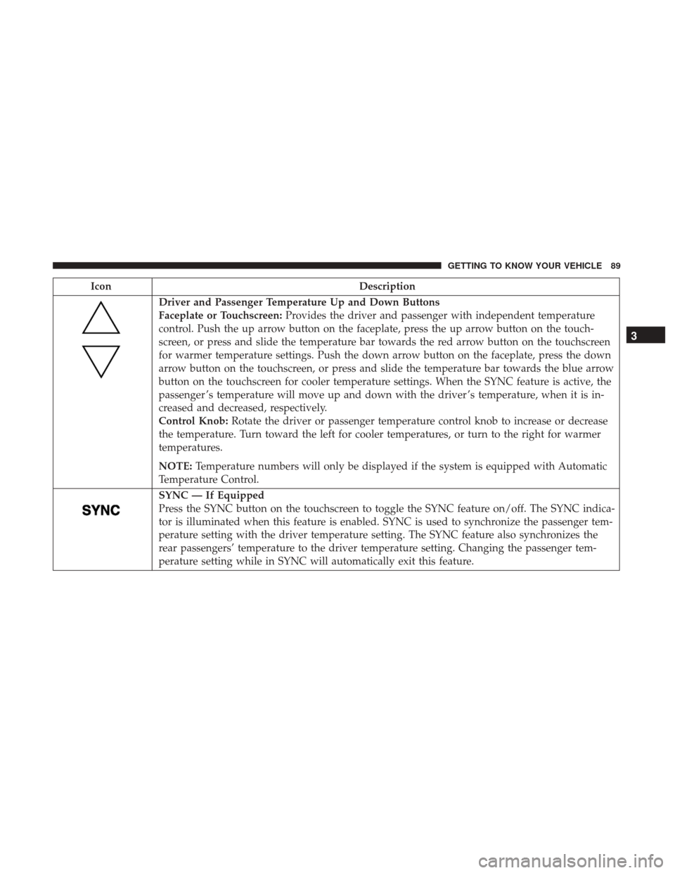
Driver and Passenger Temperature Up and Down Buttons
Faceplate or Touchscreen:Provides the driver and passenger with independent temperature
control. Push the up arrow button on the faceplate, press the up arrow button on the touch-
screen, or press and slide the temperature bar towards the red arrow button on the touchscreen
for warmer temperature settings. Push the down arrow button on the faceplate, press the down
arrow button on the touchscreen, or press and slide the temperature bar towards the blue arrow
button on the touchscreen for cooler temperature settings. When the SYNC feature is active, the
passenger ’s temperature will move up and down with the driver ’s temperature, when it is in-
creased and decreased, respectively.
Control Knob: Rotate the driver or passenger temperature control knob to increase or decrease
the temperature. Turn toward the left for cooler temperatures, or turn to the right for warmer
temperatures.
NOTE: Temperature numbers will only be displayed if the system is equipped with Automatic
Temperature Control.
SYNC — If Equipped
Press the SYNC button on the touchscreen to toggle the SYNC feature on/off. The SYNC indica-
tor is illuminated when this feature is enabled. SYNC is used to synchronize the passenger tem-
perature setting with the driver temperature setting. The SYNC feature also synchronizes the
rear passengers’ temperature to the driver temperature setting. Changing the passenger tem-
perature setting while in SYNC will automatically exit this feature.
3
GETTING TO KNOW YOUR VEHICLE 89
Page 132 of 698
Power Inverter — If Equipped
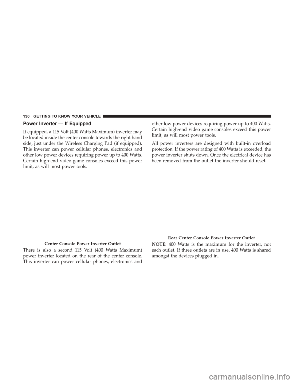
If equipped, a 115 Volt (400 Watts Maximum) inverter may
be located inside the center console towards the right hand
side, just under the Wireless Charging Pad (if equipped).
This inverter can power cellular phones, electronics and
other low power devices requiring power up to 400 Watts.
Certain high-end video game consoles exceed this power
limit, as will most power tools.
There is also a second 115 Volt (400 Watts Maximum)
power inverter located on the rear of the center console.
This inverter can power cellular phones, electronics andother low power devices requiring power up to 400 Watts.
Certain high-end video game consoles exceed this power
limit, as will most power tools.
All power inverters are designed with built-in overload
protection. If the power rating of 400 Watts is exceeded, the
power inverter shuts down. Once the electrical device has
been removed from the outlet the inverter should reset.
NOTE:
400 Watts is the maximum for the inverter, not
each outlet. If three outlets are in use, 400 Watts is shared
amongst the devices plugged in.
Center Console Power Inverter Outlet
Rear Center Console Power Inverter Outlet
130 GETTING TO KNOW YOUR VEHICLE
Page 147 of 698
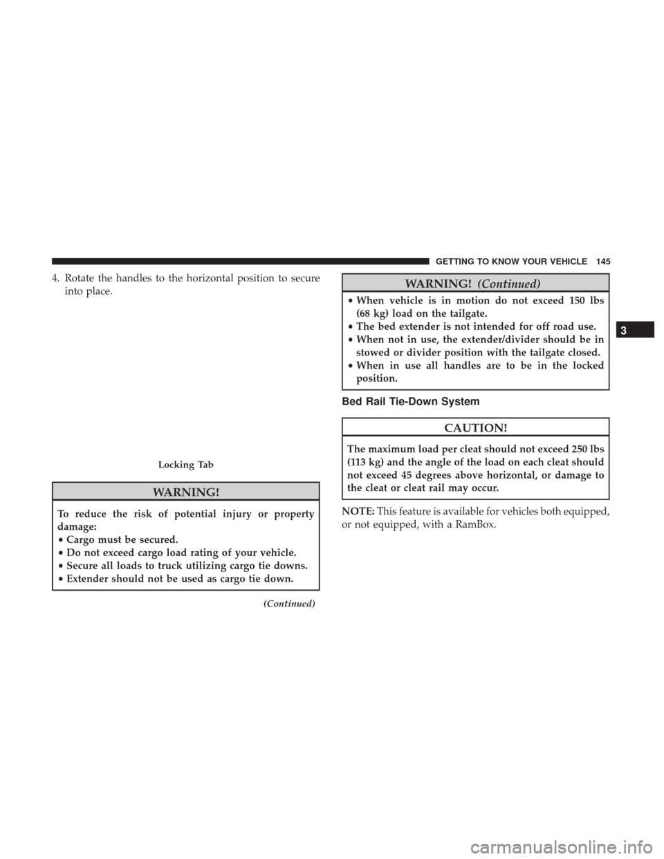
4. Rotate the handles to the horizontal position to secureinto place.
WARNING!
To reduce the risk of potential injury or property
damage:
•Cargo must be secured.
• Do not exceed cargo load rating of your vehicle.
• Secure all loads to truck utilizing cargo tie downs.
• Extender should not be used as cargo tie down.
(Continued)
WARNING! (Continued)
•When vehicle is in motion do not exceed 150 lbs
(68 kg) load on the tailgate.
• The bed extender is not intended for off road use.
• When not in use, the extender/divider should be in
stowed or divider position with the tailgate closed.
• When in use all handles are to be in the locked
position.
Bed Rail Tie-Down System
CAUTION!
The maximum load per cleat should not exceed 250 lbs
(113 kg) and the angle of the load on each cleat should
not exceed 45 degrees above horizontal, or damage to
the cleat or cleat rail may occur.
NOTE: This feature is available for vehicles both equipped,
or not equipped, with a RamBox.
Locking Tab
3
GETTING TO KNOW YOUR VEHICLE 145
Page 152 of 698
WARNING!
To avoid inhaling carbon monoxide, which is deadly,
the exhaust system on vehicles equipped with “Cap or
Slide-In Campers” should extend beyond the over-
hanging camper compartment and be free of leaks.
Locking Tailgate
The tailgate can be locked using the key fob lock button.
TRI-FOLD TONNEAU COVER — IF EQUIPPED
Your vehicle may be equipped with a Tri-Fold Tonneau
Cover which consists of different features:
•Easy Tri-Fold cover
• Tonneau fore aft locator
• Crosscar inside bed locator
• Front and rear clamps
• Stowage strap
• Locking capability
NOTE: The Tonneau Cover can be folded up and secured
at the front of the box without removing it completely.
Tri-Fold Tonneau Cover Removal
To remove the Tonneau Cover follow the following steps:
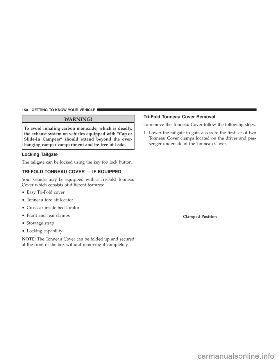
1. Lower the tailgate to gain access to the first set of two Tonneau Cover clamps located on the driver and pas-
senger underside of the Tonneau Cover.
Clamped Position
150 GETTING TO KNOW YOUR VEHICLE
Page 153 of 698
2. Slide the release of the locking lever toward the center oftruck bed to release the clamp, and pull the handle
downward into the intermediate position.
Slide Locking Lever Inward
Pull Handle Downward
3
GETTING TO KNOW YOUR VEHICLE 151
Page 154 of 698
3. Push the fully released clamp upward toward the un-derside of the Tonneau Cover. Push the handle firmly to
lock into the stowed position. 4. Lift up on the Tonneau Cover and fold it back onto the
second panel.
Intermediate PositionStowed Position
152 GETTING TO KNOW YOUR VEHICLE
Page 156 of 698
NOTE:When folding the center and rear panels, the
sections MUSTbe held together to avoid damage to the
cover material.
7. Be sure to clip both stowage straps together to ensurethe cover stays together.
Incorrect Folding — Will Cause Damage
Correct Folding — Hold Panels Together
154 GETTING TO KNOW YOUR VEHICLE
Page 157 of 698
8. With two people, remove the cover.
NOTE:Be sure the Tonneau Cover has been folded com-
pletely before removing.
Tri-Fold Tonneau Cover Installation
To install the Tonneau Cover follow these steps:
1. Position the folded Tonneau Cover on the truck bed and push the cover forward against the front of the truck
bed. The Tonneau Cover centers itself when placed on
the vehicle.
2. Slide the release of the locking levers on the first set of clamps toward the center of the truck bed to release the
clamps from the stowed position. Then pull the handles
downward into the intermediate position.
Fully Folded Tonneau Cover
1 — Stowage Strap
2 — Tonneau Cover Bumper And Seat
Slide Locking Lever Inward
3
GETTING TO KNOW YOUR VEHICLE 155
Page 159 of 698
4. With the yellow bumper of the swing lever securelyengaged under the flange, push the clamp handle
upward toward the underside of the Tonneau Cover.
Push the handle firmly to lock into place.
5. Disengage the stowage straps.
6. Unfold Tonneau Cover to the second panel position.
Step Four
1 — Fully Engaged Swing Lever
Clamped Position
3
GETTING TO KNOW YOUR VEHICLE 157
Page 165 of 698
charged. If the pointer moves to either extreme left or
right and remains there during normal driving, the
electrical system should be serviced.
NOTE: In vehicles equipped with Stop/Start, a reduced
voltage may be present during an Autostop.
3. Instrument Cluster Display
•When the appropriate conditions exist, this display
shows the instrument cluster display messages. Refer
to “Instrument Cluster Display” in “Getting To Know
Your Instrument Panel” for further information.
4. Oil Pressure Gauge •The pointer should always indicate the oil pressure
when the engine is running. A continuous high or low
reading under normal driving conditions may indicate
a lubrication system malfunction. Immediate service
should be obtained from an authorized dealer.
NOTE: In vehicles equipped with Stop/Start, an oil pres-
sure indication of zero is normal during an Autostop. 5. Speedometer
•Indicates vehicle speed.
6. Fuel Gauge •The pointer shows the level of fuel in the fuel tank
when the ignition is in the ON/RUN position.
•
The fuel pump symbol points to the side of the
vehicle where the fuel door is located.
7. Temperature Gauge
•The gauge pointer shows engine coolant temperature.
The pointer positioned within the normal range indi-
cates that the engine cooling system is operating
satisfactorily.
• The gauge pointer will likely indicate a higher tem-
perature when driving in hot weather, up mountain
grades, or when towing a trailer. It should not be
allowed to exceed the upper limits of the normal
operating range.
4
GETTING TO KNOW YOUR INSTRUMENT PANEL 163