audio Ram 1500 2019 Owner's Manual
[x] Cancel search | Manufacturer: RAM, Model Year: 2019, Model line: 1500, Model: Ram 1500 2019Pages: 698, PDF Size: 9.04 MB
Page 170 of 698
The instrument cluster display menu items may consist of
the following:
•Speedometer
• Vehicle Info
• Driver Assist
• Fuel Economy Info
• Trip •
Stop/Start
• Trailer Tow
• Audio
• Stored Messages
• Screen Setup
• Vehicle Settings (Not Equipped with a Uconnect touch-
screen radio)
The system allows the driver to select information by
pushing the following instrument cluster display control
buttons located on the left side of the steering wheel:
Premium Instrument Cluster Display
1 – Instrument Cluster Display Controls
2 – Instrument Cluster Display Screen
Instrument Cluster Display Control Buttons
168 GETTING TO KNOW YOUR INSTRUMENT PANEL
Page 175 of 698
Audio
Push and release theupordown arrow button until the
Audio Menu icon/title is highlighted in the instrument
cluster display. This menu will display the audio source
information, including the Song name, Artist name, and
audio source with an accompanying graphic.
Phone Call Status
When a call is incoming, a Phone Call Status pop-up will
display on the screen. The pop-up will remain until the
phone is answered or ignored.
NOTE: The call status will temporarily replace the previ-
ous media source information displayed on the screen.
When the pop-up is no longer displayed, the display will
return to the last used screen.
Stored Messages
Push and release the upordown arrow button until the
Messages Menu item is highlighted. This feature shows the
number of stored warning messages. Push and release the
right orleft arrow buttons to cycle through stored
messages.
Screen Setup
NOTE: The Screen Setup feature can only be used while
the vehicle is in PARK.
Push and release the upordown arrow button until the
Screen Setup Menu Icon/Title is highlighted in the instru-
ment cluster display. Push and release the OKbutton to
enter the sub-menus and follow the prompts on the screen
as needed. The Screen Setup feature allows you to change
what information is displayed in the instrument cluster as
well as the location that information is displayed.
Screen Setup Driver Selectable Items
Upper Left
• None
• Compass (default setting – Premium)
• Outside Temp (default setting – Base)
• Time
• Range
• Average Fuel Economy
• Current Fuel Economy
• Trip A Distance
4
GETTING TO KNOW YOUR INSTRUMENT PANEL 173
Page 176 of 698
•Trip B Distance
• Trailer Trip – If Equipped
• Trailer Brake – If Equipped
• Oil Pressure – If Equipped
• Coolant Temperature – If Equipped
• Oil Temperature – If Equipped
• Battery Voltage – If Equipped
• Transmission Temperature – If Equipped
• Oil Life – If Equipped
Upper Center
• None
• Compass
• Outside Temp
• Time
• Range
• Average Fuel Economy
• Current Fuel Economy
• Trip A Distance •
Trip B Distance
• Trailer Trip – If Equipped
• Audio
• Speedometer (default setting)
• Menu Title
Upper Right
• None
• Compass (default setting – Premium)
• Outside Temp (default setting – Base)
• Time
• Range
• Average Fuel Economy
• Current Fuel Economy
• Trip A Distance
• Trip B Distance
• Trailer Trip – If Equipped
• Trailer Brake – If Equipped
• Oil Pressure – If Equipped
174 GETTING TO KNOW YOUR INSTRUMENT PANEL
Page 178 of 698
•Coolant Temperature
• Oil Temperature
• Battery Voltage (default setting)
• Transmission Temperature
• Oil Life
Lower Right – If Equipped
• None
• Compass
• Outside Temp
• Time
• Range
• Average Fuel Economy
• Current Fuel Economy
• Trip A Distance
• Trip B Distance
• Trailer Trip
• Trailer Brake •
Oil Pressure (default setting)
• Coolant Temperature
• Oil Temperature
• Battery Voltage
• Transmission Temperature
• Oil Life
Favorite Menus
• Speedometer
• Vehicle Info
• Driver Assist (show/hide) – If Equipped
• Fuel Economy (show/hide)
• Trip Info (show/hide)
• Stop/Start
• Trailer Tow (show/hide)
• Audio (show/hide)
• (Stored) Messages
• Screen Setup
176 GETTING TO KNOW YOUR INSTRUMENT PANEL
Page 180 of 698
The electrical loads that may be switched off (if equipped),
and vehicle functions which can be affected by load
reduction:
•Heated Seats/Vented Seats/Heated Wheel
• Rear Defroster And Heated Mirrors
• HVAC System
• 115V AC Power Inverter System
• Audio and Telematics System
Loss of the battery charge may indicate one or more of the
following conditions:
• The charging system cannot deliver enough electrical
power to the vehicle system because the electrical loads
are larger than the capability of charging system. The
charging system is still functioning properly.
• Turning on all possible vehicle electrical loads (e.g.
HVAC to max settings, exterior and interior lights,
overloaded power outlets +12V, 115V AC, USB ports)
during certain driving conditions (city driving, towing,
frequent stopping).
• Installing options like additional lights, upfitter electri-
cal accessories, audio systems, alarms and similar de-
vices. •
Unusual driving cycles (short trips separated by long
parking periods).
• The vehicle was parked for an extended period of time
(weeks, months).
• The battery was recently replaced and was not charged
completely.
• The battery was discharged by an electrical load left on
when the vehicle was parked.
• The battery was used for an extended period with the
engine not running to supply radio, lights, chargers,
+12V portable appliances like vacuum cleaners, game
consoles and similar devices.
What to do when an electrical load reduction action
message is present (“Battery Saver On” or “Battery Saver
Mode”)
During a trip:
• Reduce power to unnecessary loads if possible:
– Turn off redundant lights (interior or exterior).
– Check what may be plugged in to power outlets +12V, 115V AC, USB ports.
– Check HVAC settings (blower, temperature).
– Check the audio settings (volume).
178 GETTING TO KNOW YOUR INSTRUMENT PANEL
Page 181 of 698
After a trip:
•Check if any aftermarket equipment was installed (ad-
ditional lights, upfitter electrical accessories, audio sys-
tems, alarms) and review specifications if any (load and
Ignition Off Draw currents).
• Evaluate the latest driving cycles (distance, driving time
and parking time).
• The vehicle should have service performed if the mes-
sage is still present during consecutive trips and the
evaluation of the vehicle and driving pattern did not
help to identify the cause.
WARNING LIGHTS AND MESSAGES
The warning/indicator lights will illuminate in the instru-
ment panel together with a dedicated message and/or
acoustic signal when applicable. These indications are
indicative and precautionary and as such must not be
considered as exhaustive and/or alternative to the infor-
mation contained in the Owner ’s Manual, which you are
advised to read carefully in all cases. Always refer to the
information in this chapter in the event of a failure indica-
tion. All active telltales will display first if applicable. The system check menu may appear different based upon
equipment options and current vehicle status. Some tell-
tales are optional and may not appear.
Red Warning Lights
— Seat Belt Reminder Warning Light
This warning light indicates when the driver or passenger
seat belt is unbuckled. When the ignition is first placed in
the ON/RUN or ACC/ON/RUN position and if the
driver ’s seat belt is unbuckled, a chime will sound and the
light will turn on. When driving, if the driver or front
passenger seat belt remains unbuckled, the Seat Belt Re-
minder Light will flash or remain on continuously and a
chime will sound.
Refer to “Occupant Restraint Systems” in “Safety” for
further information.
— Air Bag Warning Light
This warning light will illuminate to indicate a fault with
the air bag, and will turn on for four to eight seconds as a
bulb check when the ignition is placed in the ON/RUN or
ACC/ON/RUN position. This light will illuminate with a
single chime when a fault with the air bag has been
detected, it will stay on until the fault is cleared. If the light
4
GETTING TO KNOW YOUR INSTRUMENT PANEL 179
Page 369 of 698
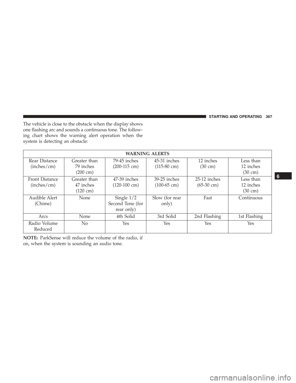
The vehicle is close to the obstacle when the display shows
one flashing arc and sounds a continuous tone. The follow-
ing chart shows the warning alert operation when the
system is detecting an obstacle:
WARNING ALERTS
Rear Distance (inches/cm) Greater than
79 inches(200 cm) 79-45 inches
(200-115 cm) 45-31 inches
(115-80 cm) 12 inches
(30 cm) Less than
12 inches (30 cm)
Front Distance (inches/cm) Greater than
47 inches(120 cm) 47-39 inches
(120-100 cm) 39-25 inches
(100-65 cm) 25-12 inches
(65-30 cm) Less than
12 inches (30 cm)
Audible Alert (Chime) None
Single 1/2
Second Tone (for rear only) Slow (for rear
only) Fast
Continuous
Arcs None4th Solid 3rd Solid 2nd Flashing 1st Flashing
Radio Volume Reduced No
Yes YesYes Yes
NOTE: ParkSense will reduce the volume of the radio, if
on, when the system is sounding an audio tone.
6
STARTING AND OPERATING 367
Page 440 of 698
2. The LED light located between the ASSIST and SOSbuttons on the overhead console will turn green once a
connection to a SOS operator has been made.
3. Once a connection between the vehicle and a SOS operator is made, the SOS Call system may transmit the
following important vehicle information to a SOS op-
erator:
• Indication that the occupant placed a SOS Call.
• The vehicle brand.
• The last known GPS coordinates of the vehicle.
4. You should be able to speak with the SOS operator through the vehicle audio system to determine if addi-
tional help is needed.
WARNING!
ALWAYS obey traffic laws and pay attention to the road.
ALWAYS drive safely with your hands on the steering
wheel. You have full responsibility and assume all risks
related to the use of the features and applications in this
vehicle. Only use the features and applications when it
is safe to do so. Failure to do so may result in an accident
involving serious injury or death.
NOTE:
•Your vehicle may be transmitting data as authorized
by the subscriber.
•
Once a connection is made between the vehicle’s SOS
Call system and the SOS operator, the SOS operator may
be able to open a voice connection with the vehicle to
determine if additional help is needed. Once the SOS
operator opens a voice connection with the vehicle’s
SOS Call system, the operator should be able to speak
with you or other vehicle occupants and hear sounds
occurring in the vehicle. The vehicle’s SOS Call system
will attempt to remain connected with the SOS operator
until the SOS operator terminates the connection.
5. The SOS operator may attempt to contact appropriate emergency responders and provide them with impor-
tant vehicle information and GPS coordinates.
WARNING!
•If anyone in the vehicle could be in danger (e.g., fire
or smoke is visible, dangerous road conditions or
location), do not wait for voice contact from an
Emergency Services Agent. All occupants should exit
the vehicle immediately and move to a safe location.
(Continued)
438 IN CASE OF EMERGENCY
Page 441 of 698
WARNING!(Continued)
•Never place anything on or near the vehicle’s oper-
able network and GPS antennas. You could prevent
operable network and GPS signal reception, which
can prevent your vehicle from placing an emergency
call. An operable network and GPS signal reception
is required for the SOS Call system to function
properly.
• The SOS Call system is embedded into the vehicle’s
electrical system. Do not add aftermarket electrical
equipment to the vehicle’s electrical system. This
may prevent your vehicle from sending a signal to
initiate an emergency call. To avoid interference that
can cause the SOS Call system to fail, never add
aftermarket equipment (e.g., two-way mobile radio,
CB radio, data recorder, etc.) to your vehicle’s electri-
cal system or modify the antennas on your vehicle. IF
YOUR VEHICLE LOSES BATTERY POWER FOR
ANY REASON (INCLUDING DURING OR AFTER
AN ACCIDENT), THE UCONNECT FEATURES,
APPS AND SERVICES, AMONG OTHERS, WILL
NOT OPERATE.
(Continued)
WARNING! (Continued)
•Modifications to any part of the SOS Call system
could cause the air bag system to fail when you need
it. You could be injured if the air bag system is not
there to help protect you.
SOS Call System Limitations
Vehicles sold in Mexico DO NOThave SOS Call system
capabilities.
SOS or other emergency line operators in Mexico may not
answer or respond to SOS system calls.
If the SOS Call system detects a malfunction, any of the
following may occur at the time the malfunction is de-
tected, and at the beginning of each ignition cycle:
• The overhead console light located between the ASSIST
and SOS buttons will continuously be illuminated red.
• The Device Screen will display the following message:
“Vehicle device requires service. Please contact your
dealer.”
• An In-Vehicle Audio message will state “Vehicle device
requires service. Please contact your dealer.”
7
IN CASE OF EMERGENCY 439
Page 456 of 698
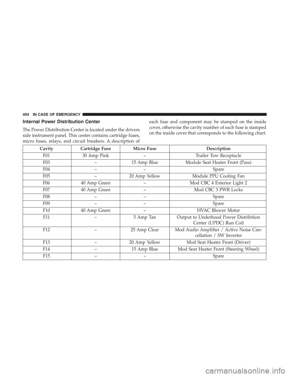
Internal Power Distribution Center
The Power Distribution Center is located under the drivers
side instrument panel. This center contains cartridge fuses,
micro fuses, relays, and circuit breakers. A description ofeach fuse and component may be stamped on the inside
cover, otherwise the cavity number of each fuse is stamped
on the inside cover that corresponds to the following chart.
Cavity
Cartridge Fuse Micro Fuse Description
F01 30 Amp Pink –Trailer Tow Receptacle
F03 –15 Amp Blue Module Seat Heater Front (Pass)
F04 –– Spare
F05 –20 Amp Yellow Module PPU Cooling Fan
F06 40 Amp Green –Mod CBC 4 Exterior Light 2
F07 40 Amp Green –Mod CBC 3 PWR Locks
F08 –– Spare
F09 –– Spare
F10 40 Amp Green –HVAC Blower Motor
F11 –5 Amp Tan Output to Underhood Power Distribition
Center (UPDC) Run Coil
F12 –25 Amp Clear Mod Audio Amplifier / Active Noise Can-
cellation / SW Inverter
F13 –20 Amp Yellow Mod Seat Heater Front (Driver)
F14 –15 Amp Blue Mod Seat Heater Front (Steering Wheel)
F15 –– Spare
454 IN CASE OF EMERGENCY