light Ram 1500 2020 Service Manual
[x] Cancel search | Manufacturer: RAM, Model Year: 2020, Model line: 1500, Model: Ram 1500 2020Pages: 674, PDF Size: 32.69 MB
Page 116 of 674
114 GETTING TO KNOW YOUR VEHICLE
4. Watch for the HomeLink® indicator to change flashrates. When it changes, it is programmed. It may take up
to 30 seconds or longer in rare cases. The garage door
may open and close while you are programming.
5. Press and hold the programmed HomeLink® button and observe the indicator light.
NOTE:
• If the indicator light stays on constantly, programming is complete and the garage door/device should activate
when the HomeLink® button is pressed.
• To program the two remaining HomeLink® buttons, repeat each step for each remaining button. DO NOT erase
the channels.
If you unplugged the garage door opener/device for
programming, plug it back in at this time.
Reprogramming A Single HomeLink® Button (Canadian/
Gate Operator)
To reprogram a channel that has been previously trained,
follow these steps:
1. Place the ignition in the ON/RUN position. 2. Press and hold the desired HomeLink® button until the
indicator light begins to flash after 20 seconds. Do not
release the button.
3. Without releasing the button, proceed with “Canadian/ Gate Operator Programming” step 2 and follow all
remaining steps.
Using HomeLink®
To operate, push and release the programmed HomeLink®
button. Activation will now occur for the programmed
device (i.e. garage door opener, gate operator, security
system, entry door lock, home/office lighting, etc.) The
hand-held transmitter of the device may also be used at any
time.
Security
It is advised to erase all channels before you sell or turn in
your vehicle.
To do this, push and hold the two outside buttons for 20 seconds
until the orange indicator flashes. Note that all channels will be
erased. Individual channels cannot be erased.
The HomeLink® Universal Transceiver is disabled when the
Vehicle Security Alarm is active.
2020_DT_1500_OM_US.book Page 114
Page 130 of 674
128 GETTING TO KNOW YOUR VEHICLE
If your vehicle is equipped with “Smart Fold”, the entire
center section of the 40/20/40 seat folds forward for access
of cupholders and console storage.Rear Armrest Cupholder With Smart FoldElectrical Power Outlets
The auxiliary 12 Volt (13 Amp) power outlet can provide
power for in-cab accessories designed for use with the
standard “cigar lighter” plug. The 12 Volt power outlets
and 5 Volt (2.5 Amp) USB Port (Charge Only) have a cap
attached to the outlet indicating “12V DC,” together with
either a key symbol, battery symbol, or USB symbol.
A key symbol indicates that the ignition must be in the ON/
RUN or ACC positions for the outlet to provide power. The
battery symbol indicates that the outlet is connected to the
battery, and can provide power at all times.
CAUTION!
• Do not exceed the maximum power of 160 Watts (13 Amps) at 12 Volts. If the 160 Watts (13 Amps) power rating is
exceeded, the fuse protecting the system will need to be
replaced.
• Power outlets are designed for accessory plugs only. Do not insert any other object in the power outlets as this
will damage the outlet and blow the fuse. Improper use
of the power outlet can cause damage not covered by
your New Vehicle Limited Warranty.
2020_DT_1500_OM_US.book Page 128
Page 132 of 674
130 GETTING TO KNOW YOUR VEHICLE
When the vehicle is turned off, be sure to unplug any equip-
ment as to not drain the battery of the vehicle. All accessories
connected to the outlet(s) should be removed or turned off
when the vehicle is not in use to protect the battery against
discharge.
WARNING!
To avoid serious injury or death:
• Only devices designed for use in this type of outlet should be inserted into any 12 Volt outlet.
• Do not touch with wet hands.
• Close the lid when not in use and while driving the vehicle.
• If this outlet is mishandled, it may cause an electric shock and failure.
CAUTION!
• Many accessories that can be plugged in draw power from the vehicle's battery, even when not in use (i.e.,
cellular phones, etc.). Eventually, if plugged in long
enough, the vehicle's battery will discharge sufficiently
to degrade battery life and/or prevent the engine from
starting.
• Accessories that draw higher power (i.e., coolers, vacuum cleaners, lights, etc.), will discharge the battery
even more quickly. Only use these intermittently and
with greater caution.
• After the use of high power draw accessories, or long periods of the vehicle not being started (with accesso -
ries still plugged in), the vehicle must be driven a suffi -
cient length of time to allow the generator to recharge
the vehicle's battery.
2020_DT_1500_OM_US.book Page 130
Page 136 of 674

134 GETTING TO KNOW YOUR VEHICLE
Wireless Charging Pad — If Equipped
Wireless Charging PadYour vehicle may be equipped with a 15W 3A Qi wireless
charging pad located inside of the center console just below
the CD player (if equipped). This charging pad is designed to
wirelessly charge your Qi enabled mobile phone. Qi is a stan
-
dard that uses magnetic induction to transfer power to your
mobile device.
Your mobile phone must be designed for Qi wireless
charging. If the phone is not equipped with Qi wireless
charging functionality, an aftermarket sleeve or a specialized
back plate can be purchased from your mobile phone
provider or an local electronics retailer. Please see your
phone’s owner’s manual for further information.
The wireless charging pad is equipped with an anti-slip mat,
an adjustable cradle to hold your mobile phone in place and
an LED indicator light.
WARNING!
To avoid serious injury or death:
• Do not insert any objects into the receptacles.
• Do not touch with wet hands.
• Close the lid when not in use.
• If this outlet is mishandled, it may cause an electric shock and failure.
CAUTION!
The key fob should not be placed on the charging pad or
within 15 cm (150 mm) of it. Doing so can cause excessive
heat buildup and damage to the fob. Placing the fob in
close proximity of the charging pad blocks the fob from
being detected by the vehicle and prevents the vehicle
from starting.
2020_DT_1500_OM_US.book Page 134
Page 140 of 674
138 GETTING TO KNOW YOUR VEHICLE
RamBox Push Button And Keyhole LockThe interior of the RamBox will automatically illuminate
when the lid is opened. The timing can be adjusted through
your touchscreen.
Refer to “Uconnect Settings” in “Multimedia” for further
information.
Cargo bins feature two removable drain plugs (to allow
water to drain from bins). To remove plug, pull up on the
edge. To install push plug downward into drain hole.
If equipped, a power inverter can be found inside the
RamBox.
Refer to “Electrical Power Outlets” in this chapter for further
information.
NOTE:
Provisions are provided in the bins for cargo dividers. These
accessories (in addition to other RamBox accessories) are
available from Mopar.
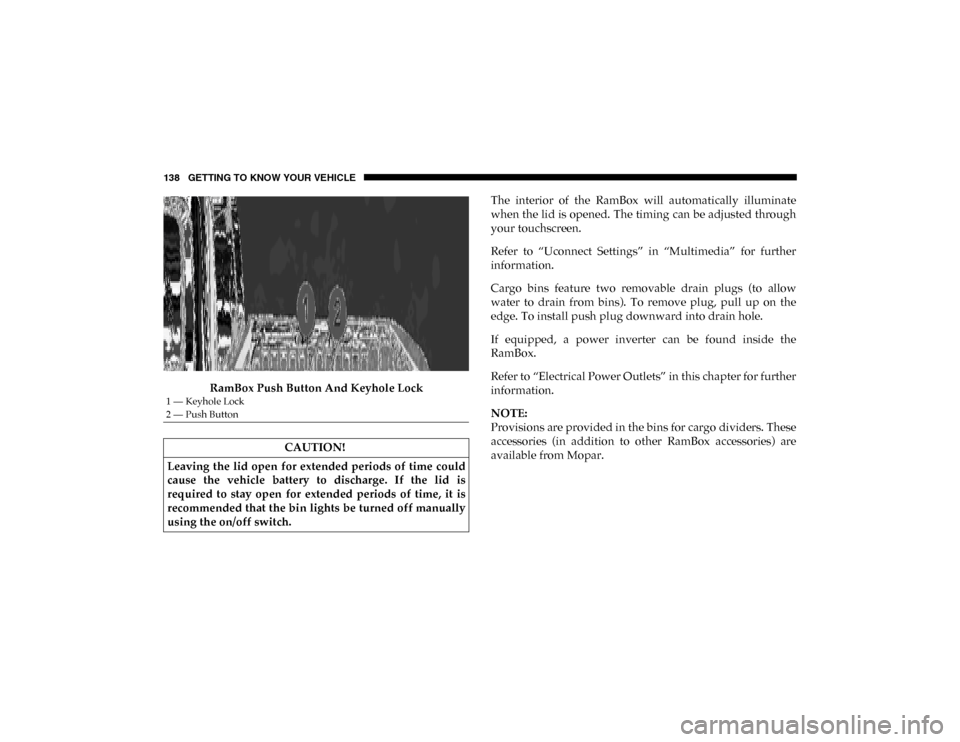
1 — Keyhole Lock
2 — Push Button
CAUTION!
Leaving the lid open for extended periods of time could
cause the vehicle battery to discharge. If the lid is
required to stay open for extended periods of time, it is
recommended that the bin lights be turned off manually
using the on/off switch.
2020_DT_1500_OM_US.book Page 138
Page 149 of 674
GETTING TO KNOW YOUR VEHICLE 147
NOTE:
When a cap or pickup camper is installed on a vehicle, an
alternate Center High-Mounted Stop Light (CHMSL) must
be provided.
EASY-OFF TAILGATE
To simplify mounting of a camper unit with an overhang, the
tailgate can be removed.
NOTE:
The electric connector at the bottom of the tailgate must be
disconnected prior to removing the tailgate.
Disconnecting The Rear Camera And Remote Keyless
Entry
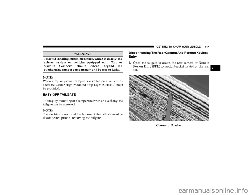
1. Open the tailgate to access the rear camera or RemoteKeyless Entry (RKE) connector bracket located on the rear
sill.
Connector Bracket
WARNING!
To avoid inhaling carbon monoxide, which is deadly, the
exhaust system on vehicles equipped with “Cap or
Slide-In Campers” should extend beyond the
overhanging camper compartment and be free of leaks.
2
2020_DT_1500_OM_US.book Page 147
Page 171 of 674
GETTING TO KNOW YOUR INSTRUMENT PANEL 169
3. Push and release the right arrow button to access the ”Oil
Life” screen.
4. Push and hold the OK button to reset oil life. If conditions
are met, the gauge and numeric display will update to
show 100%. If conditions are not met a pop up message of
“To reset oil life engine must be off with ignition in run”
will be displayed (for five seconds), and the user will
remain at the Oil Life screen.
5. Push and release the up or down arrow button to exit the
submenu screen.
NOTE:
If the indicator message illuminates when you start the
vehicle, the oil change indicator system did not reset. If
necessary, repeat this procedure.
Display Menu Items
Push and release the up or down arrow button until the
desired selectable menu icon is highlighted in the instrument
cluster display.
Speedometer
Push and release the up or down arrow button until the
speedometer menu item is highlighted in the instrument
cluster display. Push and release the OK button to cycle the
display between mph and km/h. Vehicle Info
Push and release the
up or down arrow button until the
Vehicle Info menu icon is displayed in the instrument cluster
display. Push and release the left or right arrow button to
scroll through the information submenus and push and
release the OK button to select or reset the resettable
submenus.
• Tire Pressure
• Trans Temp (Automatic only)
• Oil Temperature
• Oil Life
• Air Suspension — If Equipped
• Coolant Temperature — If Equipped
• Oil Pressure — If Equipped
• Battery Voltage — If Equipped
• Gauge Summary — If Equipped
• Engine Hours
3
2020_DT_1500_OM_US.book Page 169
Page 173 of 674
GETTING TO KNOW YOUR INSTRUMENT PANEL 171
LaneSense — If Equipped
The instrument cluster display displays the current Lane-
Sense system settings. The information displayed depends
on LaneSense system status and the conditions that need to
be met. For further information, refer to “LaneSense — If
Equipped” in “Starting And Operating.”
Fuel Economy
Push and release the up or down arrow button until the Fuel
Economy menu item is highlighted in the instrument cluster
display. Push and hold the OK button to reset Average Fuel
Economy.
• Current Fuel Economy Gauge
• Average Fuel Economy Value
• Range To Empty
Trip
Push and release the up or down arrow button until the Trip
menu item is highlighted in the instrument cluster display.
Push and release the right or left arrow buttons to enter the
submenus of Trip A and Trip B. The Trip A or Trip B infor -
mation will display the following: • Distance
• Average Fuel Economy
• Elapsed Time
Push and hold
OK button to reset all information.
Stop/Start — If Equipped
Push and release the up or down arrow button until the
Stop/Start icon/title is highlighted in the instrument cluster
display. The screen will display the Stop/Start status.
Trailer Tow
Push and release the up or down arrow button until the
Trailer Tow menu item is highlighted in the instrument
cluster display. Push and release the right or left arrow
buttons to cycle through the following trailer trip informa -
tion:
• Trip (trailer specific) Distance: Push and hold the OK
button to reset the distance.
• Trailer Brake • Output
• Type
• Gain
3
2020_DT_1500_OM_US.book Page 171
Page 174 of 674
172 GETTING TO KNOW YOUR INSTRUMENT PANEL
Audio
Push and release the up or down arrow button until the
Audio Menu icon/title is highlighted in the instrument
cluster display. This menu will display the audio source
information, including the Song name, Artist name, and
audio source with an accompanying graphic.
Phone Call Status
When a call is incoming, a Phone Call Status pop-up will
display on the screen. The pop-up will remain until the
phone is answered or ignored.
NOTE:
The call status will temporarily replace the previous media
source information displayed on the screen. When the
pop-up is no longer displayed, the display will return to the
last used screen. Stored Messages
Push and release the
up or down arrow button until the
Messages Menu item is highlighted. This feature shows the
number of stored warning messages. Push and release the
right or left arrow buttons to cycle through stored messages.
Screen Setup
NOTE:
The Screen Setup feature can only be used while the vehicle
is in PARK (P).
Push and release the up or down arrow button until the
Screen Setup Menu Icon/Title is highlighted in the instru-
ment cluster display. Push and release the OK button to
enter the sub-menus and follow the prompts on the screen as
needed. The Screen Setup feature allows you to change what
information is displayed in the instrument cluster as well as
the location that information is displayed.
2020_DT_1500_OM_US.book Page 172
Page 179 of 674
GETTING TO KNOW YOUR INSTRUMENT PANEL 177
NOTE:
• The charging system is independent from load reduction.The charging system performs a diagnostic on the
charging system continuously.
• If the Battery Charge Warning Light is on it may indicate a problem with the charging system. Refer to “Battery
Charge Warning Light” in “Getting To Know Your Instru -
ment Panel” for further information.
The electrical loads that may be switched off (if equipped),
and vehicle functions which can be affected by load reduc -
tion:
• Heated Seats / Vented Seats / Heated Wheel
• Rear Defroster And Heated Mirrors
• HVAC System
• 115 Volts AC Power Inverter System
• Audio and Telematics System
Loss of the battery charge may indicate one or more of the
following conditions:
• The charging system cannot deliver enough electrical power to the vehicle system because the electrical loads are
larger than the capability of charging system. The charging
system is still functioning properly. • Turning on all possible vehicle electrical loads (e.g. HVAC
to max settings, exterior and interior lights, overloaded
power outlets +12 Volts, 115V AC, USB ports) during
certain driving conditions (city driving, towing, frequent
stopping).
• Installing options like additional lights, upfitter electrical accessories, audio systems, alarms and similar devices.
• Unusual driving cycles (short trips separated by long parking periods).
• The vehicle was parked for an extended period of time (weeks, months).
• The battery was recently replaced and was not charged completely.
• The battery was discharged by an electrical load left on when the vehicle was parked.
• The battery w as used for an extended period with t he engine not running to supply radio, lights, chargers,
+12 Volt portable appliances like vacuum cleaners,
gam e consoles and similar devices.
3
2020_DT_1500_OM_US.book Page 177