display RAM 1500 2021 Owners Manual
[x] Cancel search | Manufacturer: RAM, Model Year: 2021, Model line: 1500, Model: RAM 1500 2021Pages: 496, PDF Size: 20.89 MB
Page 296 of 496
294MULTIMEDIA
How It Works
1. Use the Uconnect App to find the
destination.
There are multiple ways to find a destina -
tion. After selecting the “Location” tab at
the bottom of the App, press the search box
to browse through one of the categories pro -
vided, or type the name or keyword in the
search box at the top of the App. You can
also select categories such as Favorites or
Contact List.
2. Select your destination from the list that appears. Location information will then be
displayed on the map.
From this screen, you will be able to:
View the location on a map.
See the distance from your current loca-
tion.
Send the address by selecting “Send to
Vehicle” from the mobile app.
3. Send the destination to the Uconnect Navigation in your vehicle. You can also call
the destination by pressing the Call button. 4. Confirm your destination inside your vehicle
by pressing the Send To Vehicle option on
the pop-up that appears on the radio
touchscreen.
Requirements
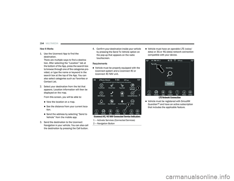
Vehicle must be properly equipped with the
Uconnect system and a Uconnect 4C or
Uconnect 4C NAV unit.
Uconnect 4C/4C NAV Connected Service Indicators
Vehicle must have an operable LTE (voice/
data) or 3G or 4G (data) network connection
compatible with your device.
LTE Network Connection
Vehicle must be registered with SiriusXM
Guardian™ and have an active subscription
that includes the applicable feature.
1 — Activate Services (Connected Services)
2 — Navigation Button
21_DT_OM_EN_USC_t.book Page 294
Page 300 of 496
298MULTIMEDIA
In order to provide the Monthly Vehicle Health
Report, the Uconnect system in your vehicle
may collect and transmit vehicle data to
SiriusXM Guardian™ and to FCA, such as your
vehicle’s health and performance, your
vehicle’s location, your utilization of the
features in your vehicle, and other data.
This data collection and transmission begins
when you enroll in SiriusXM Guardian™ and will
continue even if you cancel your SiriusXM
Guardian™ subscription unless you call
SiriusXM Guardian™ Customer Care and tell
them to deactivate your Uconnect Services.
Please see the Uconnect Privacy Policy for more
information, located at
www.driveuconnect.com/connectedservices/
privacy (US Residents) or
www.driveuconnect.ca (Canadian Residents).
For more information on SiriusXM Guardian™
private policy, see https://siriusxmcvs.com/
privacy-policy.Vehicle Health Alert
Description
Your vehicle will send you an email alert if it
senses a problem with one of your vehicle’s key
systems. For further information, go to your
Owner’s website.
NOTE:
Vehicle Health Alert emails require you to
register and activate services. During this
process you will be asked to provide an email
address to which the reports will be sent.
In-Vehicle Notifications — If Equipped
Description
Your vehicle will send you notifications to
remind you when services are needed, or to
alert you of other important information, such
as recall notices. When you receive a
notification through your touchscreen, press OK
to dismiss the message, or press Call Care to
speak with a SiriusXM Guardian™ Customer
Care agent. NOTE:
Pressing OK or the X button on the pop-up
screen will dismiss or close the pop-up, and the
In-Vehicle Messages mailbox will display. In the
Mailbox, you can reopen messages or delete
messages.
Amazon Alexa® Skill — If Equipped
Enjoy the convenience of using your voice to
command your vehicle with Amazon Alexa®!
With Amazon Alexa®, you can connect to your
vehicle and remotely access key services and
features.
If your vehicle is equipped with Uconnect
Navigation, you can send a destination directly
to your vehicle using Alexa®.
If you need assistance, you can always ask
Alexa® for help, or complete a list of commands
by saying: “Alexa®, ask
with my car.”
21_DT_OM_EN_USC_t.book Page 298
Page 309 of 496
MULTIMEDIA307
Use of any of the Uconnect Services including
SiriusXM Guardian™ is deemed to be your
consent to the collection, use and disclosure of
this information in accordance with the
Uconnect Privacy Policy. If you do not want this
information to be collected, used, or shared,
you must cancel your Uconnect services in their
entirety by contacting us as referenced in the
Uconnect Privacy Policy.
OFF-ROAD PAGES — IF EQUIPPED
Your vehicle may be equipped with Off-Road
Pages which display vehicle information related
to the drivetrain, transfer case, and coolant/oil
gauges.
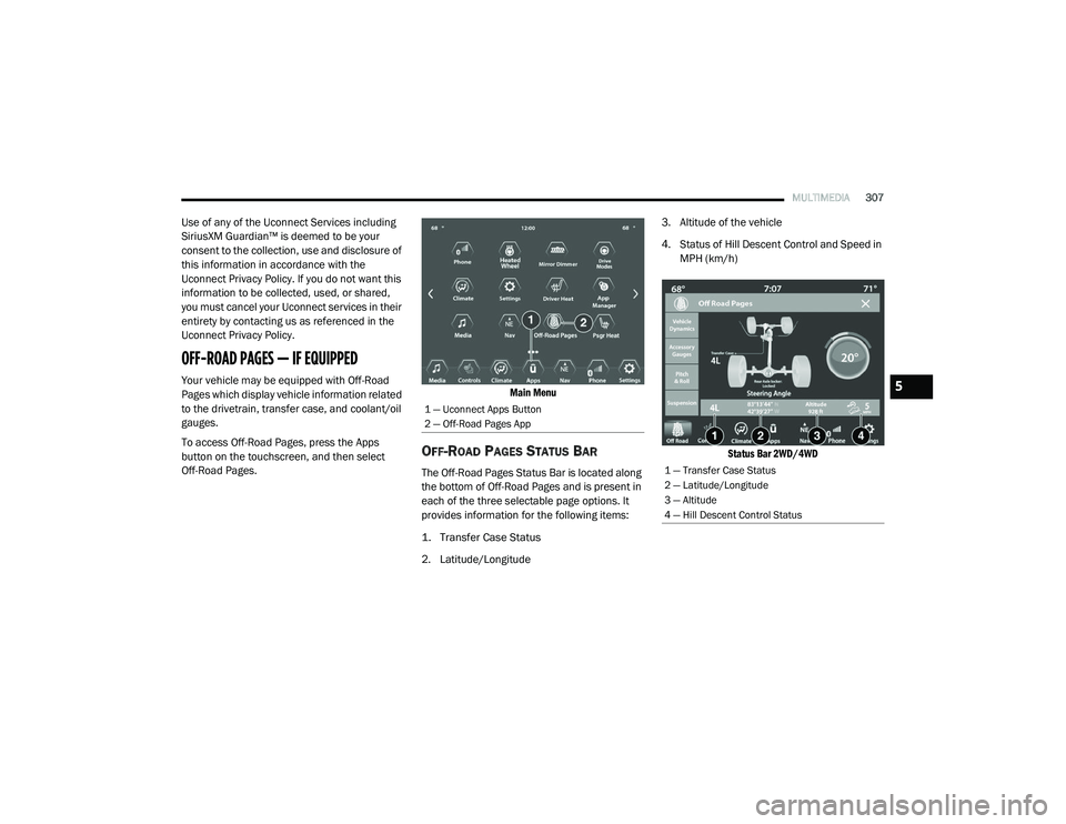
To access Off-Road Pages, press the Apps
button on the touchscreen, and then select
Off-Road Pages.
Main Menu
OFF-ROAD PAGES STATUS BAR
The Off-Road Pages Status Bar is located along
the bottom of Off-Road Pages and is present in
each of the three selectable page options. It
provides information for the following items:
1. Transfer Case Status
2. Latitude/Longitude3. Altitude of the vehicle
4. Status of Hill Descent Control and Speed in
MPH (km/h)
Status Bar 2WD/4WD
1 — Uconnect Apps Button
2 — Off-Road Pages App
1 — Transfer Case Status
2 — Latitude/Longitude
3 — Altitude
4 — Hill Descent Control Status
5
21_DT_OM_EN_USC_t.book Page 307
Page 310 of 496
308MULTIMEDIA
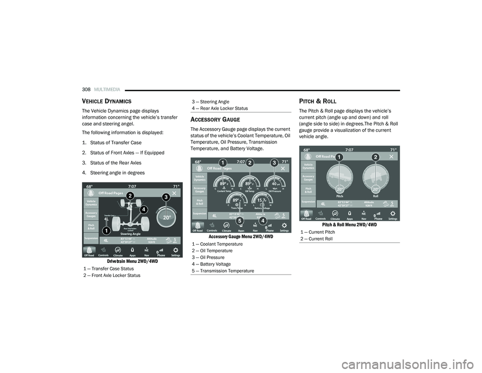
VEHICLE DYNAMICS
The Vehicle Dynamics page displays
information concerning the vehicle’s transfer
case and steering angel.
The following information is displayed:
1. Status of Transfer Case
2. Status of Front Axles — If Equipped
3. Status of the Rear Axles
4. Steering angle in degrees
Drivetrain Menu 2WD/4WD
ACCESSORY GAUGE
The Accessory Gauge page displays the current
status of the vehicle’s Coolant Temperature, Oil
Temperature, Oil Pressure, Transmission
Temperature, and Battery Voltage.
Accessory Gauge Menu 2WD/4WD
PITCH & ROLL
The Pitch & Roll page displays the vehicle’s
current pitch (angle up and down) and roll
(angle side to side) in degrees.The Pitch & Roll
gauge provide a visualization of the current
vehicle angle.
Pitch & Roll Menu 2WD/4WD
1 — Transfer Case Status
2 — Front Axle Locker Status
3 — Steering Angle
4 — Rear Axle Locker Status
1 — Coolant Temperature
2 — Oil Temperature
3 — Oil Pressure
4 — Battery Voltage
5 — Transmission Temperature
1 — Current Pitch
2 — Current Roll
21_DT_OM_EN_USC_t.book Page 308
Page 311 of 496
MULTIMEDIA309
SUSPENSION
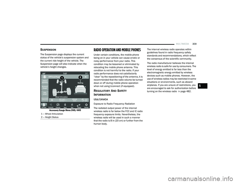
The Suspension page displays the current
status of the vehicle’s suspension system and
the current ride height of the vehicle. The
Suspension page will also indicate when the
vehicle’s height changes.
Accessory Gauge Menu 2WD/4WD
RADIO OPERATION AND MOBILE PHONES
Under certain conditions, the mobile phone
being on in your vehicle can cause erratic or
noisy performance from your radio. This
condition may be lessened or eliminated by
relocating the mobile phone antenna. This
condition is not harmful to the radio. If your
radio performance does not satisfactorily
“clear” by the repositioning of the antenna, it is
recommended that the radio volume be turned
down or off during mobile phone operation
when not using Uconnect (if equipped).
REGULATORY AND SAFETY
I
NFORMATION
USA/CANADA
Exposure to Radio Frequency Radiation
The radiated output power of the internal
wireless radio is far below the FCC and IC radio
frequency exposure limits. Nevertheless, the
wireless radio will be used in such a manner
that the radio is 8 in (20 cm) or further from the
human body. The internal wireless radio operates within
guidelines found in radio frequency safety
standards and recommendations, which reflect
the consensus of the scientific community.
The radio manufacturer believes the internal
wireless radio is safe for use by consumers. The
level of energy emitted is far less than the
electromagnetic energy emitted by wireless
devices such as mobile phones. However, the
use of wireless radios may be restricted in some
situations or environments, such as aboard
airplanes. If you are unsure of restrictions, you
are encouraged to ask for authorization before
turning on the wireless radio Ú
page 482.
1 — Wheel Articulation
2 — Height Status
5
21_DT_OM_EN_USC_t.book Page 309
Page 316 of 496
314SAFETY
(Continued)
Full Off — If Equipped
This mode is intended for off-highway or
off-road use only and should not be used on any
public roadways. In this mode, TCS and ESC
features are turned off. To enter the “Full Off”
mode, push and hold the ESC OFF switch for five
seconds while the vehicle is stopped with the
engine running. After five seconds, a chime will
sound, the ESC OFF Indicator Light will
illuminate, and the “ESC OFF” message will
display in the instrument cluster. To turn ESC on
again, momentarily push the ESC OFF switch.NOTE:
System may switch from ESC “Full Off” to
“Partial Off” mode when vehicle exceeds a
predetermined speed. When the vehicle speed
slows below the predetermined speed the
system will return to ESC “Full Off”.
ESC modes may also be affected by drive
modes (if equipped).
ESC Activation/Malfunction Indicator Light
And ESC OFF Indicator Light
The ESC Activation/Malfunction
Indicator Light in the instrument
cluster will come on when the ignition
is placed in the ON/RUN mode. It
should go out with the engine running. If the
ESC Activation/Malfunction Indicator Light
comes on continuously with the engine running,
a malfunction has been detected in the ESC
system. If this light remains on after several
ignition cycles, and the vehicle has been driven
several miles (kilometers) at speeds greater
than 30 mph (48 km/h), see an authorized
dealer as soon as possible to have the problem
diagnosed and corrected.
WARNING!
When in “Partial Off” mode, the TCS func -
tionality of ESC, (except for the limited slip
feature described in the TCS section), has
been disabled and the “ESC OFF Indicator
Light” will be illuminated. When in “Partial
Off” mode, the engine power reduction
feature of TCS is disabled, and the
enhanced vehicle stability offered by the
ESC system is reduced.
Trailer Sway Control (TSC) is disabled when
the ESC system is in the “Partial Off” mode.
WARNING!
In the ESC “Full Off” mode, the engine
torque reduction and stability features are
disabled. Therefore, enhanced vehicle
stability offered by the ESC system is
unavailable. In an emergency evasive
maneuver, the ESC system will not engage
to assist in maintaining stability. ESC “Full
Off” mode is intended for off-highway or
off-road use only.
The Electronic Stability Control (ESC)
cannot prevent the natural laws of physics
from acting on the vehicle, nor can it
increase the traction afforded by prevailing
road conditions. ESC cannot prevent all
accidents, including those resulting from
excessive speed in turns, driving on very
slippery surfaces, or hydroplaning. ESC also
cannot prevent collisions.
WARNING! (Continued)
21_DT_OM_EN_USC_t.book Page 314
Page 325 of 496

SAFETY323
a trailer will be detected using the blind spot
radar within 90 seconds of forward move -
ment of the vehicle. The vehicle must be
moving above 6 mph (10 km/h) to activate the feature. Once the trailer has been
detected, the system will default to the
maximum blind spot zone until the length has
been verified. You will see “Auto” in the
instrument panel cluster .
Maximum Mode — When “Max Mode” is
selected, the system will default to the
maximum blind spot zone regardless of what
size trailer is attached .
NOTE:
Selected setting is stored when the ignition is
placed in the OFF position. To change this
setting, it must be selected through the
Uconnect settings Ú page 237.
Trailer Length Detection
Once the trailer presence has been established,
the trailer length will be established (by making
a 90 degree turn) and then the trailer length
category (example 10-20 ft (3 m to 6 m)) will be
displayed. This can take up to 30 seconds after
completing the turn. NOTE:
During the same ignition cycle, if the vehicle is
at a standstill for a minimum of 90 seconds, a
new “trailer detection request” is enabled by
the system once the vehicle resumes motion.
Maximum length supported by the Trailer Merge
Assist feature is 39.5 ft (12 m). Trailer length is
considered the forward most portion of the
trailer hitch to the rearward most portion of the
body, fascia/bumper, or ramp of the trailer.
Maximum width supported by the Trailer Merge
Assist feature is 8.5 ft (2.59 m). Trailer width is
measured at the widest portion of the trailer
and may include wheels, tires, finders, or rails.
NOTE:
Fifth wheel or gooseneck trailers are not
supported by Trailer Merge Assist.
NOTE:
The ability to detect a trailer may be degraded in
crowded or busy environments. Busy parking
lots, narrow areas surrounded with trees, or any
other crowded area may prevent the radar
sensors from being able to adequately detect
the trailer. The system will try to detect a trailer
at every ignition cycle or 90 seconds of stand
-
still.
Trailer Length Detection
Trailer length will be identified and placed into
one of the following categories:
Trailer length up to 10 ft (3 m) — Blind spot
zone will be adjusted to 10 ft (3 m) .
Trailer length between 10 ft to 20 ft (3 m to
6 m) — Blind spot zone will be adjusted to
20 ft (6 m) .
Trailer length between 20 ft to 30 ft (6 m to
9 m) — Blind spot zone will be adjusted to
30 ft (9 m) .
1 — Trailer Length
2 — Trailer Width
3 — Trailer Hitch
6
21_DT_OM_EN_USC_t.book Page 323
Page 326 of 496

324SAFETY
Trailer length between 30 ft and 39.5 ft (9 m
to 12 m) — Blind spot zone will be adjusted to
Max distance .
NOTE:
Trailer length is determined within +/- 3 ft (1 m)
of actual length. Trailers that are the same size
as the category limit, 10/20/30 ft (3/6/9 m),
could be subject to being placed in the category
above or below the correct one.
Trailer Merge Warning
Trailer Merge Warning is the extension of the
blind spot function to cover the length of the
trailer, plus a safety margin, to warn the driver
when there is a vehicle in the adjacent lane. The
driver is alerted by the illumination of the BSM
warning light located in the outside mirror on
the side the other vehicle is detected on. In
addition, an audible (chime) alert will be heard
and radio volume will be reduced Ú page 322.
NOTE:
The Trailer Merge Alert system DOES NOT
alert the driver about rapidly approaching
vehicles that are outside the detection zones.
The Blind Spot Monitoring (BSM) system may
experience drop outs (blinking on and off) of the side mirror warning indicator lamps when
a motorcycle or any small object remains at
the side of the vehicle for extended periods of
time (more than a couple of seconds).
Crowded areas such as parking lots, neigh
-
borhoods, etc. may lead to an increased
amount of false alerts. This is normal opera -
tion.
FORWARD COLLISION WARNING (FCW)
W
ITH MITIGATION — IF EQUIPPED
FCW with Mitigation provides the driver with
audible warnings, visual warnings (within the
instrument cluster display), and may apply a
brake jerk to warn the driver when it detects a potential frontal collision. The warnings and
limited braking are intended to provide the
driver with enough time to react, avoid or
mitigate the potential collision.
NOTE:
FCW monitors the information from the forward
looking sensors as well as the Electronic Brake
Controller (EBC), to calculate the probability of a
forward collision. When the system determines
that a forward collision is probable, the driver
will be provided with audible and visual warn-
ings as well as a possible brake jerk warning.
If the driver does not take action based upon
these progressive warnings, then the system
will provide a limited level of active braking to
help slow the vehicle and mitigate the potential
forward collision. If the driver reacts to the warn
-
ings by braking and the system determines that
the driver intends to avoid the collision by
braking but has not applied sufficient brake
force, the system will compensate and provide
additional brake force as required.
If a FCW with Mitigation event begins at a speed
below 32 mph (52 km/h), the system may
provide the maximum braking possible to miti -
gate the potential forward collision. If the
WARNING!
The Blind Spot Monitoring system is only an
aid to help detect objects in the blind spot
zones. The BSM system is not designed to
detect pedestrians, bicyclists, or animals.
Even if your vehicle is equipped with the BSM
system, always check your vehicle’s mirrors,
glance over your shoulder, and use your turn
signal before changing lanes. Failure to do so
can result in serious injury or death.
21_DT_OM_EN_USC_t.book Page 324
Page 327 of 496
SAFETY325
Forward Collision Warning with Mitigation event
stops the vehicle completely, the system will
hold the vehicle at standstill for two seconds
and then release the brakes.
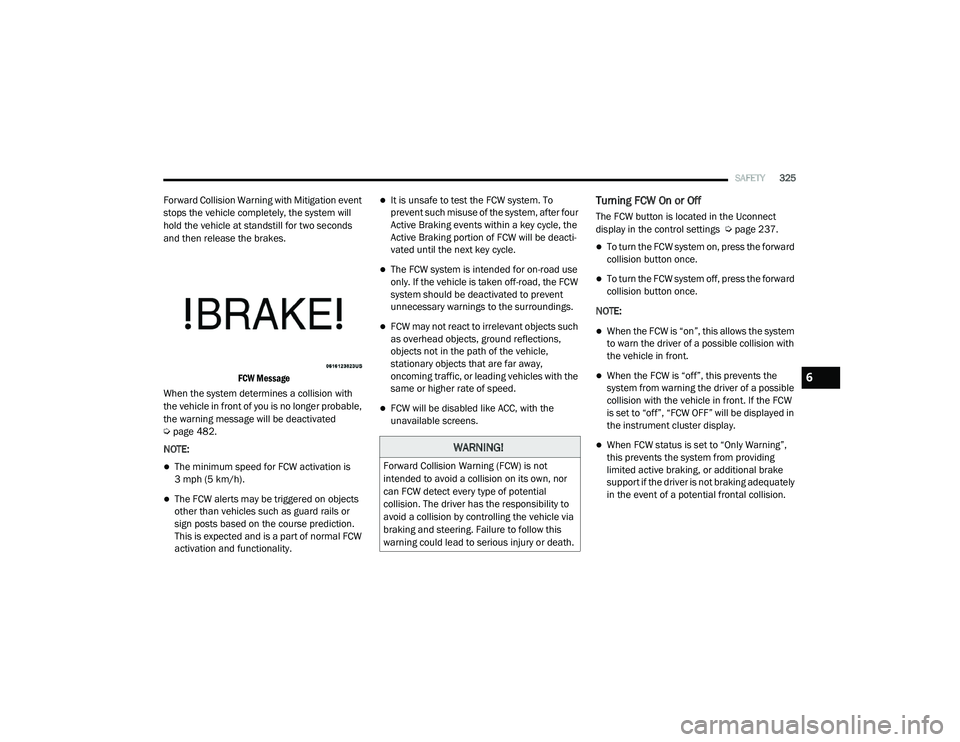
FCW Message
When the system determines a collision with
the vehicle in front of you is no longer probable,
the warning message will be deactivated
Ú page 482.
NOTE:
The minimum speed for FCW activation is
3 mph (5 km/h).
The FCW alerts may be triggered on objects
other than vehicles such as guard rails or
sign posts based on the course prediction.
This is expected and is a part of normal FCW
activation and functionality.
It is unsafe to test the FCW system. To
prevent such misuse of the system, after four
Active Braking events within a key cycle, the
Active Braking portion of FCW will be deacti -
vated until the next key cycle.
The FCW system is intended for on-road use
only. If the vehicle is taken off-road, the FCW
system should be deactivated to prevent
unnecessary warnings to the surroundings.
FCW may not react to irrelevant objects such
as overhead objects, ground reflections,
objects not in the path of the vehicle,
stationary objects that are far away,
oncoming traffic, or leading vehicles with the
same or higher rate of speed.
FCW will be disabled like ACC, with the
unavailable screens.
Turning FCW On or Off
The FCW button is located in the Uconnect
display in the control settings Ú page 237.
To turn the FCW system on, press the forward
collision button once.
To turn the FCW system off, press the forward
collision button once.
NOTE:
When the FCW is “on”, this allows the system
to warn the driver of a possible collision with
the vehicle in front.
When the FCW is “off”, this prevents the
system from warning the driver of a possible
collision with the vehicle in front. If the FCW
is set to “off”, “FCW OFF” will be displayed in
the instrument cluster display.
When FCW status is set to “Only Warning”,
this prevents the system from providing
limited active braking, or additional brake
support if the driver is not braking adequately
in the event of a potential frontal collision.WARNING!
Forward Collision Warning (FCW) is not
intended to avoid a collision on its own, nor
can FCW detect every type of potential
collision. The driver has the responsibility to
avoid a collision by controlling the vehicle via
braking and steering. Failure to follow this
warning could lead to serious injury or death.
6
21_DT_OM_EN_USC_t.book Page 325
Page 328 of 496
326SAFETY
When FCW status is set to “Warning and
Braking”, this allows the system to warn the
driver of a possible collision with the vehicle
in front using audible/visual warnings and it
applies autonomous braking.
The FCW system state is defaulted to “Full
On” from one ignition cycle to the next. If the
system is turned off, it will reset to “Full On”
when the vehicle is restarted.
FCW Braking Status And Sensitivity
The FCW Sensitivity and Active Braking status
are programmable through the Uconnect
system Ú page 237.
Far
When the sensitivity of FCW is set to the
“Far” setting and the system status is
“Only Warning”, this allows the system to
warn the driver of a possible more distant
collision with the vehicle in front using
audible/visual warnings.
More cautious drivers that do not mind
frequent warnings may prefer this
setting.
Medium
When the sensitivity of FCW is set to the
“Medium” setting and the system status
is “Only Warning”, this allows the system
to warn the driver of a possible collision
with the vehicle in front using audible/
visual warnings.
Near
When the sensitivity of FCW is set to the
“Near” setting and the system status is
“Only Warning”, this allows the system to
warn the driver of a possible closer colli -
sion with the vehicle in front using
audible/visual warnings.
This setting provides less reaction time
than the “Far” and “Medium” settings,
which allows for a more dynamic driving
experience.
More dynamic or aggressive drivers that
want to avoid frequent warnings may
prefer this setting.
FCW Limited Warning
If the instrument cluster displays “ACC/FCW
Limited Functionality” or “ACC/FCW Limited
Functionality Clean Front Windshield”
momentarily, there may be a condition that
limits FCW functionality. Although the vehicle is
still driveable under normal conditions, the
active braking may not be fully available. Once
the condition that limited the system
performance is no longer present, the system
will return to its full performance state. If the
problem persists, see an authorized dealer.
Service FCW Warning
If the system turns off, and the instrument
cluster displays:
ACC/FCW Unavailable Service Required
Cruise/FCW Unavailable Service Required
This indicates there is an internal system fault.
Although the vehicle is still drivable under
normal conditions, have the system checked by
an authorized dealer.
21_DT_OM_EN_USC_t.book Page 326