engine RAM 1500 2022 Manual PDF
[x] Cancel search | Manufacturer: RAM, Model Year: 2022, Model line: 1500, Model: RAM 1500 2022Pages: 496, PDF Size: 18.03 MB
Page 178 of 496

176STARTING AND OPERATING
SYSTEM MALFUNCTION
If there is a malfunction in the Stop/Start system,
the system will not shut down the engine. A
“SERVICE STOP/START SYSTEM” message will
appear in the instrument cluster display
Úpage 128.
The system will need to be checked by an
authorized dealer.
CRUISE CONTROL SYSTEMS — IF EQUIPPED
Your vehicle may be equipped with the Cruise
Control system, or the Adaptive Cruise Control
(ACC) system:
Cruise Control will keep your vehicle at a
constant preset speed.
Adaptive Cruise Control (ACC) will adjust the
vehicle speed up to the preset speed to main -
tain a distance with the vehicle ahead.
NOTE:
In vehicles equipped with ACC, if ACC is not
enabled, Fixed Speed Cruise Control will not
detect vehicles directly ahead of you. Always be
aware of the feature selected.
Only one Cruise Control feature can operate at a
time. For example, if Fixed Speed Cruise Control
is enabled, Adaptive Cruise Control will be
unavailable, and vice versa.
CRUISE CONTROL
When engaged, the Cruise Control takes over
accelerator operations at speeds greater than
20 mph (32 km/h).
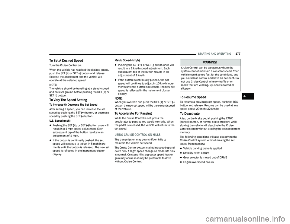
The Cruise Control buttons are located on the right
side of the steering wheel.
Cruise Control Buttons
To Activate
Push the on/off button to activate the Cruise
Control. The cruise indicator light in the instrument
cluster display will illuminate. To turn the system
off, push the on/off button a second time. The
cruise indicator light will turn off. The system
should be turned off when not in use.
1 — SET (+)/Accel
2 — CANC/Cancel
3 — SET (-)/Decel
4 — On/Off
5 — RES/Resume
WARNING!
Cruise Control can be dangerous where the
system cannot maintain a constant speed. Your
vehicle could go too fast for the conditions, and
you could lose control and have an accident. Do
not use Cruise Control in heavy traffic or on
roads that are winding, icy, snow-covered or
slippery.
WARNING!
Leaving the Cruise Control system on when not
in use is dangerous. You could accidentally set
the system or cause it to go faster than you
want. You could lose control and have an
accident. Always ensure the system is off when
you are not using it.
22_DT_OM_EN_USC_t.book Page 176
Page 179 of 496
STARTING AND OPERATING177
To Set A Desired Speed
Turn the Cruise Control on.
When the vehicle has reached the desired speed,
push the SET (+) or SET (-) button and release.
Release the accelerator and the vehicle will
operate at the selected speed.
NOTE:The vehicle should be traveling at a steady speed
and on level ground before pushing the SET (+) or
SET (-) button.
To Vary The Speed Setting
To Increase Or Decrease The Set Speed
After setting a speed, you can increase the set
speed by pushing the SET (+) button, or decrease
speed by pushing the SET (-) button.
U.S. Speed (mph)
Pushing the SET (+) , or SET (-) button once will
result in a 1 mph speed adjustment. Each
subsequent tap of the button results in an
adjustment of 1 mph.
If the button is continually pushed, the set
speed will continue to adjust in 5 mph incre -
ments until the button is released. The new set
speed is reflected in the instrument cluster
display. Metric Speed (km/h)
Pushing the SET (+)
, or SET (-) button once will
result in a 1 km/h speed adjustment. Each
subsequent tap of the button results in an
adjustment of 1 km/h.
If the button is continually pushed, the set
speed will continue to adjust in 10 km/h incre -
ments until the button is released. The new set
speed is reflected in the instrument cluster
display.
NOTE:When you override and push the SET (+) or SET (-)
button, the new set speed will be the current speed
of the vehicle.
To Accelerate For Passing
While the Cruise Control is set, press the
accelerator to pass as you would normally. When
the pedal is released, the vehicle will return to the
set speed.
USING CRUISE CONTROL ON HILLS
The transmission may downshift on hills to
maintain the vehicle set speed.
The Cruise Control system maintains speed up and
down hills. A slight speed change on moderate hills
is normal. On steep hills, a greater speed loss or
gain may occur so it may be preferable to drive
without Cruise Control.
To Resume Speed
To resume a previously set speed, push the RES
button and release. Resume can be used at any
speed above 20 mph (32 km/h).
To Deactivate
A tap on the brake pedal, pushing the CANC
(cancel) button, or normal brake pressure while
slowing the vehicle will deactivate the Cruise
Control system without erasing the set speed from
memory.
The following conditions will also deactivate the
Cruise Control system without erasing the set
speed from memory:
Vehicle parking brake is applied
Stability event occurs
Gear selector is moved out of DRIVE
Engine overspeed occurs
WARNING!
Cruise Control can be dangerous where the
system cannot maintain a constant speed. Your
vehicle could go too fast for the conditions, and
you could lose control and have an accident. Do
not use Cruise Control in heavy traffic or on
roads that are winding, icy, snow-covered or
slippery.
4
22_DT_OM_EN_USC_t.book Page 177
Page 184 of 496
182STARTING AND OPERATING
When ACC Is Active
When you use the SET (-) button to decelerate, if
the engine’s braking power does not slow the
vehicle sufficiently to reach the set speed, the
brake system will automatically slow the
vehicle.
The ACC system decelerates the vehicle to a full
stop when following the vehicle in front. If your
vehicle follows the vehicle in front to a standstill,
after two seconds the driver will either have to
push the RES (resume) button, or apply the
accelerator pedal to reengage the ACC to the
existing set speed.
The ACC system maintains set speed when
driving uphill and downhill. However, a slight
speed change on moderate hills is normal. In
addition, downshifting may occur while climbing
uphill or descending downhill. This is normal
operation and necessary to maintain set speed.
When driving uphill and downhill, the ACC
system will cancel if the braking temperature
exceeds normal range (overheated).
Setting The Following Distance In ACC
The specified following distance for Adaptive
Cruise Control (ACC) can be set by varying the
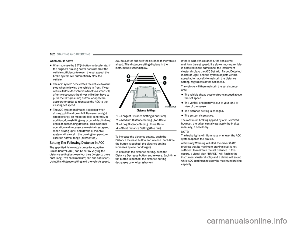
distance setting between four bars (longest), three
bars (long), two bars (medium) and one bar (short).
Using this distance setting and the vehicle speed, ACC calculates and sets the distance to the vehicle
ahead. This distance setting displays in the
instrument cluster display.
Distance Settings
To increase the distance setting, push the
Distance Increase button and release. Each time
the button is pushed, the distance setting
increases by one bar (longer).
To decrease the distance setting, push the
Distance Decrease button and release. Each time
the button is pushed, the distance setting
decreases by one bar (shorter). If there is no vehicle ahead, the vehicle will
maintain the set speed. If a slower moving vehicle
is detected in the same lane, the instrument
cluster displays the ACC Set With Target Detected
Indicator Light, and the system adjusts vehicle
speed automatically to maintain the distance
setting, regardless of the set speed.
The vehicle will then maintain the set distance
until:
The vehicle ahead accelerates to a speed above
the set speed.
The vehicle ahead moves out of your lane or
view of the sensor.
The distance setting is changed.
The system disengages.
The maximum braking applied by ACC is limited;
however, the driver can always apply the brakes
manually, if necessary.
NOTE:The brake lights will illuminate whenever the ACC
system applies the brakes.
A Proximity Warning will alert the driver if ACC
predicts that its maximum braking level is not
sufficient to maintain the set distance. If this
occurs, a visual alert “BRAKE!” will flash in the
instrument cluster display and a chime will sound
while ACC continues to apply its maximum braking
capacity.
1 — Longest Distance Setting (Four Bars)
2 — Medium Distance Setting (Two Bars)
3 — Long Distance Setting (Three Bars)
4 — Short Distance Setting (One Bar)
22_DT_OM_EN_USC_t.book Page 182
Page 209 of 496

STARTING AND OPERATING207
(Continued)
NOTE:
If the AUX button is pressed and no AUX Camera
is connected, the touchscreen will display a blue
screen along with the message “Camera
System Unavailable.” The screen can be exited
out by pressing the X in the upper right hand
corner. This will return the display back to the
previously displayed screen.
Zoom View is not available with the AUX Camera
feature.
The display will always default to the Trailer
Camera display AUX 1.
REFUELING THE VEHICLE — GASOLINE
ENGINE
The capless fuel filler is located on the left side of
the vehicle.
The capless system is sealed by two flapper doors.
1. Put the vehicle in PARK and switch the
ignition off.
2. Push the center-rear edge of the fuel filler door (3 o'clock position) and release to open.
Fuel Filler Door
3. Insert the fuel nozzle fully into the filler pipe,
the nozzle opens and holds both flapper doors
while refueling.
Fuel Filler
4. When the fuel nozzle “clicks” or shuts off, the fuel tank is full.
5. Keep the nozzle in the filler for five seconds after nozzle clicks to allow fuel to drain from
the nozzle.
6. Remove the fuel filler nozzle.
7. To close the fuel filler door, push the center-rear edge (3 o’clock position) of the fuel
filler door and then release. The fuel filler door
will latch closed.
WARNING!
Never have any smoking materials lit in or
near the vehicle when the fuel door is open or
the tank is being filled.
Never add fuel when the engine is running.
This is in violation of most state and federal
fire regulations and may cause the MIL to
turn on.
A fire may result if gasoline is pumped into a
portable container that is inside of a vehicle.
You could be burned. Always place gas
containers on the ground while filling.
CAUTION!
To avoid fuel spillage and overfilling, do not
“top off” the fuel tank after filling.
WARNING!
4
22_DT_OM_EN_USC_t.book Page 207
Page 210 of 496
208STARTING AND OPERATING
NOTE:In certain cold conditions, ice may prevent the fuel
filler door from opening. If this occurs, lightly push
on the fuel filler door around the perimeter to
break the ice build up.
REFUELING THE VEHICLE — DIESEL ENGINE
The capless fuel filler is located on the left side of
the vehicle.
The capless system is sealed by two flapper doors.
1. Put the vehicle in PARK and switch the
ignition off.
2. Open the fuel filler door.
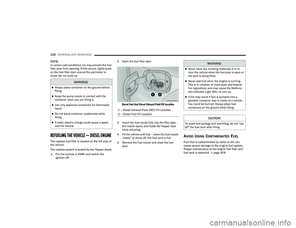
Diesel Fuel And Diesel Exhaust Fluid Fill Location
3. Insert the fuel nozzle fully into the filler pipe – the nozzle opens and holds the flapper door
while refueling.
4. Fill the vehicle with fuel – when the fuel nozzle “clicks” or shuts off, the fuel tank is full.
5. Remove the fuel nozzle and close the fuel door.
AVOID USING CONTAMINATED FUEL
Fuel that is contaminated by water or dirt can
cause severe damage to the engine fuel system.
Proper maintenance of the engine fuel filter and
fuel tank is essential Ú page 408.
WARNING!
Always place container on the ground before
filling.
Keep the pump nozzle in contact with the
container when you are filling it.
Use only approved containers for flammable
liquid.
Do not leave container unattended while
filling.
A static electric charge could cause a spark
and fire hazard.
1 — Diesel Exhaust Fluid (DEF) Fill Location
2 — Diesel Fuel Fill Location
WARNING!
Never have any smoking materials lit in or
near the vehicle when the fuel door is open or
the tank is being filled.
Never add fuel when the engine is running.
This is in violation of most state and federal
fire regulations and may cause the Malfunc -
tion Indicator Light (MIL) to turn on.
A fire may result if fuel is pumped into a
portable container that is inside of a vehicle.
You could be burned. Always place fuel
containers on the ground while filling.
CAUTION!
To avoid fuel spillage and overfilling, do not “top
off” the fuel tank after filling.
22_DT_OM_EN_USC_t.book Page 208
Page 211 of 496

STARTING AND OPERATING209
BULK FUEL STORAGE — DIESEL FUEL
If you store quantities of fuel, good maintenance of
the stored fuel is also essential. Fuel contaminated
with water will promote the growth of “microbes.”
These microbes form “slime” that will clog the fuel
filtration system and lines. Drain condensation
from the supply tank and change the line filter on
a regular basis.
NOTE:When a diesel engine is allowed to run out of fuel,
air is pulled into the fuel system.
If the vehicle will not start Úpage 414.
DIESEL EXHAUST FLUID
Your vehicle is equipped with a Selective Catalytic
Reduction (SCR) system to meet diesel emissions
standards required by the Environmental
Protection Agency. The purpose of the SCR system is to reduce levels
of oxides of nitrogen (NO
x) emitted from engines
that are harmful to our health and the environment
to a near-zero level. A small quantity of Diesel
Exhaust Fluid (DEF) is injected into the exhaust
upstream of a catalyst where, when vaporized,
converts smog-forming NO
x into harmless
nitrogen (N
2) and water vapor (H2O), two natural
components of the air we breathe.
DIESEL EXHAUST FLUID STORAGE
Diesel Exhaust Fluid (DEF) is considered a very
stable product with a long shelf life. If DEF is kept
in temperatures between 10° and 90°F (-12° and
32°C), it will last a minimum of one year.
DEF may freeze at temperatures at or below 12°F
(-11°C). The system has been designed to operate
in this environment.
NOTE:When working with DEF, it is important to know
that:
Any containers or parts that come into contact
with DEF must be DEF compatible (plastic or
stainless steel). Copper, brass, aluminum, iron
or non-stainless steel should be avoided as they
are subject to corrosion by DEF.
If DEF is spilled, it should be wiped up
completely.
ADDING DIESEL EXHAUST FLUID
The Diesel Exhaust Fluid (DEF) gauge (located on
the instrument cluster) will display the level of DEF
remaining in the tank Ú page 110.
NOTE:
Driving conditions (altitude, vehicle speed, load,
etc.) will effect the amount of DEF that is used in
your vehicle.
Outside temperature can affect DEF consump -
tion. In cold conditions, 12°F (-11°C) and
below, the DEF gauge may take longer to
operate as intended. This is a normal function of
the system.
There is an electric heater inside the DEF tank
that automatically works when necessary. If the
DEF supply does freeze, the truck will operate
normally until it thaws.WARNING!
Do not open the high pressure fuel system with
the engine running. Engine operation causes
high fuel pressure. High pressure fuel spray can
cause serious injury or death.
4
22_DT_OM_EN_USC_t.book Page 209
Page 213 of 496

STARTING AND OPERATING211
3. Stop filling the DEF tank immediately when any of the following happen: DEF stops flowing
from the fill bottle into the DEF tank, DEF
splashes out the filler neck, or a DEF pump
nozzle automatically shuts off.
4. Reinstall cap onto DEF tank.
Filling The Def Tank In Cold Climates
Your vehicle is equipped with an automatic DEF
heating system. This allows the DEF injection
system to operate properly at temperatures below
12°F (-11°C). If your vehicle is not in operation for
an extended period of time with temperatures
below 12°F (-11°C), the DEF in the tank may
freeze. Do not overfill the DEF tank. If the tank is
overfilled and freezes, it could be damaged.
Extra care should be taken when filling with
portable containers to avoid overfilling. Keep an
eye on the DEF gauge in your instrument cluster.
You may safely add a maximum of 2 gallons
(7.6 Liters) when your DEF gauge is reading at
the half mark.
VEHICLE LOADING
GROSS VEHICLE WEIGHT RATING
(GVWR)
The GVWR is the total permissible weight of your
vehicle including driver, passengers, vehicle,
options and cargo. The label also specifies
maximum capacities of front and rear Gross Axle
Weight Rating (GAWR). Total load must be limited
so GVWR and front and rear GAWR are not
exceeded.
PAYLOAD
The payload of a vehicle is defined as the allowable
load weight a truck can carry, including the weight
of the driver, all passengers, options and cargo.
GROSS AXLE WEIGHT RATING (GAWR)
The GAWR is the maximum permissible load on the
front and rear axles. The load must be distributed
in the cargo area so that the GAWR of each axle is
not exceeded.
Each axle GAWR is determined by the components
in the system with the lowest load carrying capacity
(axle, springs, tires or wheels). Heavier axles or
suspension components sometimes specified by
purchasers for increased durability does not
necessarily increase the vehicle's GVWR.
When DEF is spilled, clean the area immedi -
ately with water and use an absorbent mate -
rial to soak up the spills on the ground.
Do not attempt to start your engine if DEF is
accidentally added to the diesel fuel tank as it
can result in severe damage to your engine,
including but not limited to failure of the fuel
pump and injectors.
Never add anything other than DEF to the tank
– especially any form of hydrocarbon such as
diesel fuel, fuel system additives, gasoline, or
any other petroleum-based product. Even a
very small amount of these, less than
100 parts per million or less than 1 oz. per
78 gallons (295 liters) will contaminate the
entire DEF system and will require replace -
ment. If owners use a container, funnel or
nozzle when refilling the tank, it should either
be new or one that has only been used for
adding DEF. Mopar® provides an attachable
nozzle with its DEF for this purpose.
CAUTION!
4
22_DT_OM_EN_USC_t.book Page 211
Page 215 of 496
STARTING AND OPERATING213
COMMON TOWING DEFINITIONS
The following trailer towing related definitions will
assist you in understanding the following
information:
Gross Vehicle Weight Rating (GVWR)
The GVWR is the total allowable weight of your
vehicle. This includes driver, passengers, cargo
and tongue weight. The total load must be limited
so that you do not exceed the GVWR Ú page 211.
Gross Trailer Weight (GTW)
The GTW is the weight of the trailer plus the weight
of all cargo, consumables and equipment
(permanent or temporary) loaded in or on the
trailer in its “loaded and ready for operation”
condition.
The recommended way to measure GTW is to put
your fully loaded trailer on a vehicle scale. The
entire weight of the trailer must be supported by
the scale.
Gross Combination Weight Rating (GCWR)
The GCWR is the total allowable weight of your
vehicle and trailer when weighed in combination.
Gross Axle Weight Rating (GAWR)
The GAWR is the maximum capacity of the front
and rear axles. Distribute the load over the front
and rear axles evenly. Make sure that you do not
exceed either front or rear GAWR Úpage 211.
Tongue Weight (TW)
The TW is the downward force exerted on the hitch
ball by the trailer. You must consider this as part of
the load on your vehicle.
Trailer Frontal Area
The frontal area is the maximum height multiplied
by the maximum width of the front of a trailer.
Trailer Sway Control (TSC)
The TSC can be a mechanical telescoping link that
can be installed between the hitch receiver and the
trailer tongue that typically provides adjustable
friction associated with the telescoping motion to
dampen any unwanted trailer swaying motions
while traveling.
The electronic TSC (If equipped) recognizes a
swaying trailer and automatically applies individual
wheel brakes and/or reduces engine power to
attempt to eliminate the trailer sway.
Weight-Carrying Hitch
A weight-carrying hitch supports the trailer tongue
weight, just as if it were luggage located at a hitch
ball or some other connecting point of the vehicle.
These kinds of hitches are commonly used to tow
small and medium sized trailers.
WARNING!
If the gross trailer weight is 5,000 lb (2,267 kg)
or more, it is recommended to use a
weight-distributing hitch to ensure stable
handling of your vehicle. If you use a standard
weight-carrying hitch, you could lose control of
your vehicle and cause a collision.
WARNING!
It is important that you do not exceed the
maximum front or rear GAWR. A dangerous
driving condition can result if either rating is
exceeded. You could lose control of the vehicle
and have a collision.
4
22_DT_OM_EN_USC_t.book Page 213
Page 217 of 496

STARTING AND OPERATING215
RECOMMENDED DISTRIBUTION HITCH
ADJUSTMENT
Towing With Air Suspension — If Equipped
1. Verify that the vehicle is at the normal ride
height.
NOTE:The vehicle must remain in the engine run position
with all doors closed while attaching a trailer for
proper leveling of the air suspension system.
2. Position the truck to be ready to connect to the trailer (do not connect the trailer).
3. Enable tire jack mode through the instrument cluster or touchscreen radio settings. Tire jack
mode will be canceled and the procedure must
be restarted if the vehicle is driven at speeds
above 5 mph (8 km/h).
4. Measure the height from the top of the front wheel opening on the fender to ground; this is
height H1.
Measuring Height (H)
5. Attach the trailer to the vehicle without the weight-distributing bars connected.
6. Measure the height from the top of the front wheel opening on the fender to the ground;
this is height H2.
7. Install and adjust the tension in the weight-distributing bars per the
manufacturer’s recommendations so that the
height of the front fender is approximately
(H2-H1)/3+H1 (about 1/3 the difference
between H2 and H1 above normal ride height
[H1]). 8. Use the instrument cluster or touchscreen
radio settings and switch off tire jack mode.
Make sure the truck returns to normal ride
height. Perform a visual inspection of the
trailer and weight-distributing hitch to confirm
the manufacturer’s recommendations have
been met.
9. The truck can now be driven.
NOTE:For all towing conditions, we recommend towing
with Tow/Haul mode engaged.
Measurement Example Example Height (mm)
H1
925
H2 946
H2-H1 21
(H2-H1)/3 7
(H2-H1)/3 + H1 932
4
22_DT_OM_EN_USC_t.book Page 215
Page 221 of 496
STARTING AND OPERATING219
(Continued)
Instrument Cluster Messages:
“Calibrate Trailer ” will display when a trailer
is not calibrated and the vehicle is at a standstill
while the button is pushed.
“Calibrating Trailer” will display when the trailer
is not calibrated and the vehicle is moving while
the button is pushed.
“To Activate Trailer Steering Shift To P” will
display when the trailer is calibrated success
-
fully, the TRSC activation button is pushed and
the vehicle is not in PARK.
“Trailer Steering Ready, Shift To Reverse” will
display when the button is pushed, trailer is cali -
brated and the vehicle is in PARK.
“Trailer Steering Active” will display after the
driver shifts to REVERSE and indicates the
feature is active.
“Trailer Steering Unavailable” will display if
there is a fault in the system preventing activa -
tion, the driver’s door is open, the driver’s seat
belt is unbuckled, or the tailgate is open. Other reasons the feature may cancel:
The driver overrides steering by placing hands
on the steering wheel.
Trailer tracking is lost.
If the trailer angle becomes excessive, the
brakes apply bringing the vehicle to a stop and
then applying the parking brake.
Trailer steering button is pushed while active.
Vehicle speed goes over 8 mph (12 km/h).
Driver door is open and seat belt is unbuckled.
Transmission shifted to PARK.
Trailer Memory
The trailer steering system will automatically retain
the calibration of the previous five trailers
connected, so recalibration will not be necessary
when hooking up. The next time the vehicle is
started, place the vehicle in DRIVE and drive a
short distance. The TRSC system can then be
activated.
NOTE:Trailers may look different during day and night
conditions. In such cases, the trailer may need to
recalibrate. Some trailers (such as boat trailers) will need to
recalibrate while loaded and unloaded.
NOTE:
The system may not detect a trailer in low light
conditions. In sunny conditions, the perfor
-
mance may be degraded as shadows pass over
the trailer.
The driver is always responsible for safe opera -
tion of truck and trailer.
The driver is always in control of the truck as
well as the trailer and is responsible for
controlling the throttle and brakes.
The system may not function when the camera
lens is blocked, blurred (covered with water,
snow, ice, dirt, etc) and will not work unless the
tailgate is upright and fully latched.
TOWING REQUIREMENTS
To promote proper break-in of your new vehicle
drivetrain components, the following guidelines
are recommended.
CAUTION!
Do not tow a trailer at all during the first
500 miles (805 km) the new vehicle is driven.
The engine, axle or other parts could be
damaged.
4
22_DT_OM_EN_USC_t.book Page 219