dimensions RAM 1500 2022 Owners Manual
[x] Cancel search | Manufacturer: RAM, Model Year: 2022, Model line: 1500, Model: RAM 1500 2022Pages: 496, PDF Size: 18.03 MB
Page 13 of 496

11
SYMBOLS KEY
If you do not read this entire Owner’s Manual, you may miss important
information. Observe all Cautions and Warnings.
VAN CONVERSIONS/CAMPERS
The New Vehicle Limited Warranty does not apply to body modifications or
special equipment installed by van conversion/camper manufacturers/body
builders. US residents refer to the Warranty Information, Section 2.1.C.
Canadian residents refer to the “What Is Not Covered” section of the Warranty
Information. Such equipment includes video monitors, DVD/Blu-Ray™,
heaters, stoves, refrigerators, etc. For warranty coverage and service on these
items, contact the applicable manufacturer.
CONSUMER INFORMATION — TRUCK-CAMPER LOADING
This information is provided in fulfillment of the requirement by the United
States Government, Department of Transportation, National Highway Traffic
Safety Administration, that “every manufacturer of trucks that are capable of
accommodating slide-in campers, manufactured on or after April 1, 1973 shall
provide... at the time of original purchase to the first person who purchases the
truck”... information on Truck Camper Loading.
A slide-in camper document is provided in your vehicle’s glove compartment
that contains your Vehicle Identification Number, truck model, cargo weight
rating, and the forward/rearward limit of a camper. To obtain additional
dimensional and technical specifications for your vehicle, please visit
https://www.ramtrucks.com.
Figure 1 illustrates the dimensions describing the forward and rearward limits
of the zone in which the Center of Gravity (CG) of a slide-in camper must be
located, to provide satisfactory vehicle handling and to prevent overload of the
front and rear axles.
Figure 2 illustrates a proper match between truck and camper.
WARNING!
These statements are against operating
procedures that could result in a collision, bodily
injury and/or death.
CAUTION! These statements are against procedures that
could result in damage to your vehicle.
NOTE: A suggestion which will improve installation,
operation, and reliability. If not followed, may
result in damage.
TIP: General ideas/solutions/suggestions on easier
use of the product or functionality.
PAGE REFERENCE
ARROW Follow this reference for additional information on
a particular feature.
FOOTNOTE Supplementary and relevant information
pertaining to the topic.
1
22_DT_OM_EN_USC_t.book Page 11
Page 23 of 496

GETTING TO KNOW YOUR VEHICLE21
Replacing The Battery In The Key Fob
The replacement battery model is one CR2450
battery.
NOTE:
Customers are recommended to use a battery
obtained from Mopar®. Aftermarket coin
battery dimensions may not meet the original
OEM coin battery dimensions.
Perchlorate Material — special handling may
apply. See www.dtsc.ca.gov/hazard-
ouswaste/perchlorate for further information.
Do not touch the battery terminals that are on
the back housing or the printed circuit board.
Do not replace the coin battery if the LED on the
key fob above the top row buttons blinks when
a button is pressed. The coin battery should last
a minimum of three years with normal vehicle
usage.
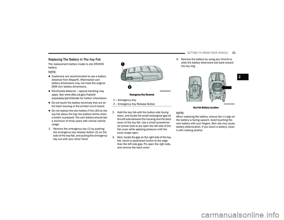
1. Remove the emergency key (1) by pushing the emergency key release button (2) on the
side of the key fob, and pulling the emergency
key out with your other hand.
Emergency Key Removal
2. Hold the key fob with the button side facing down, and locate the small rectangular gap on
the left side between the housing and the back
cover of the key fob. Use a small screwdriver
(or similar tool) to pry open the left side of the
fob cover while applying pressure until the
cover snaps open.
3. Next, locate the gap on the right side of the key fob, which is positioned further to the edge
than the left side gap. Pry open the right side,
and remove the back cover. 4. Remove the battery by using your thumb to
slide the battery downward and back toward
the key ring.
Key Fob Battery Location
NOTE:When replacing the battery, ensure the (+) sign on
the battery is facing upward. Avoid touching the
new battery with your fingers. Skin oils may cause
battery deterioration. If you touch a battery, clean
it with rubbing alcohol.
1 — Emergency Key
2 — Emergency Key Release Button
2
22_DT_OM_EN_USC_t.book Page 21
Page 206 of 496

204STARTING AND OPERATING
Set Up
The Trailer Surround View Camera system includes
an installation kit with a Trailer Surround View
Module and four Trailer Surround View Cameras
that must be installed on your trailer prior to
connecting to your vehicle. See the installation
instructions included with the Trailer Surround
View installation kit for more information. Once the
Trailer Surround View Module and cameras are
installed and the trailer is connected to the vehicle
via the 12-way connector, the settings Trailer
Surround Camera settings can be accessed. The
Trailer Surround Camera settings can be accessed
through Uconnect Settings by pressing the Trailer
soft button in the Trailer Settings or the Camera
Settings. The system requires input of the trailer
dimensions prior to use of the system.
NOTE:
If a trailer is connected but the trailer dimen -
sions have not been entered in the Trailer
Surround settings page, the system will default
to the settings page.
If a trailer is not connected and any soft button
is selected, a message will appear: “Connect
Trailer Equipped With Trailer Surround View
System”. Inputting Trailer Values
For the Trailer Surround View Camera system to
function, all fields must be entered. When a value
is needed the screen will display “Required”.
When the Trailer Type soft button is selected two
options are available: Conventional or Gooseneck/
5th Wheel.
Activation
The Trailer Surround Camera can be activated
through the Uconnect system when the vehicle is
in PARK, NEUTRAL, OR DRIVE.
When the vehicle is shifted into REVERSE,
Surround View Camera showing the Top View and
Backup Camera is the default view of the system.
Press the More Cams soft button and click the
Trailer tab to access the Trailer Cameras. Press Trailer Surround Camera soft button to
access Top View and Rear View of the trailer.
If the camera delay is turned on, the camera image
will display for up to 10 seconds after shifting out
of REVERSE. The camera image will not display for
10 seconds if the vehicle speed exceeds 8 mph
(13 km/h), the vehicle is shifted into PARK, or the
ignition is placed in the OFF position. The X button
on the touchscreen disables the display of the
camera image.
If the camera delay is turned off, the camera image
will close and display the previous screen after
shifting out of REVERSE.
Modes Of Operation
The Trailer Surround View Camera system offers
two different camera displays:
Top View split screen with one selected
mounted camera
Full screen view of a selected mounted camera
Press the More Cams soft button on the Surround
View screen and select the Trailer tab to access the
Trailer Cameras. Press Trailer Surround Camera
soft button to access the default Top View and
Rear View of the trailer.
Setting
Description
Trailer Length Input the total length of
the trailer
Trailer Width Input the total width of
the trailer
Camera Height Input the height of the
mounted camera
Trailer Type Choose the trailer type
from menu
22_DT_OM_EN_USC_t.book Page 204
Page 456 of 496

454SERVICING AND MAINTENANCE
Life Of Tire
The service life of a tire is dependent upon varying
factors including, but not limited to:
Driving style
Tire pressure - Improper cold tire inflation pres -
sures can cause uneven wear patterns to
develop across the tire tread. These abnormal
wear patterns will reduce tread life, resulting in
the need for earlier tire replacement
Distance driven
Performance tires, tires with a speed rating of V
or higher, and Summer tires typically have a
reduced tread life. Rotation of these tires per
the vehicle scheduled maintenance is highly
recommended
NOTE:Wheel Valve Stem must be replaced as well when
installing new tires due to wear and tear in existing
tires. Keep dismounted tires in a cool, dry place with as
little exposure to light as possible. Protect tires
from contact with oil, grease, and gasoline.
Replacement Tires
The tires on your new vehicle provide a balance of
many characteristics. They should be inspected
regularly for wear and correct cold tire inflation
pressures. The manufacturer strongly
recommends that you use tires equivalent to the
originals in size, quality and performance when
replacement is needed Ú
page 453. Refer to the
Tire and Loading Information placard or the
Vehicle Certification Label for the size designation
of your tire. The Load Index and Speed Symbol for
your tire will be found on the original equipment
tire sidewall.
For more information relating to the Load Index
and Speed Symbol of a tire Ú page 445.
It is recommended to replace the two front tires or
two rear tires as a pair. Replacing just one tire can
seriously affect your vehicle’s handling. If you ever
replace a wheel, make sure that the wheel’s
specifications match those of the original wheels.
It is recommended you contact an authorized tire
dealer or original equipment dealer with any
questions you may have on tire specifications or
capability. Failure to use equivalent replacement
tires may adversely affect the safety, handling, and
ride of your vehicle.
WARNING!
Tires and the spare tire should be replaced after
six years, regardless of the remaining tread.
Failure to follow this warning can result in
sudden tire failure. You could lose control and
have a collision resulting in serious injury or
death.
WARNING!
Do not use a tire, wheel size, load rating, or
speed rating other than that specified for your
vehicle. Some combinations of unapproved
tires and wheels may change suspension
dimensions and performance characteristics,
resulting in changes to steering, handling, and
braking of your vehicle. This can cause unpre -
dictable handling and stress to steering and
suspension components. You could lose
control and have a collision resulting in
serious injury or death. Use only the tire and
wheel sizes with load ratings approved for
your vehicle.
Never use a tire with a smaller load index or
capacity, other than what was originally
equipped on your vehicle. Using a tire with a
smaller load index could result in tire over -
loading and failure. You could lose control and
have a collision.
Failure to equip your vehicle with tires having
adequate speed capability can result in
sudden tire failure and loss of vehicle control.
22_DT_OM_EN_USC_t.book Page 454