check engine RAM 1500 2023 Owners Manual
[x] Cancel search | Manufacturer: RAM, Model Year: 2023, Model line: 1500, Model: RAM 1500 2023Pages: 416, PDF Size: 20.59 MB
Page 8 of 416
6
SAFETY
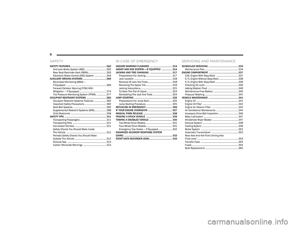
SAFETY FEATURES........................................................... 262
Anti-Lock Brake System (ABS) ................................. 262Rear Seat Reminder Alert (RSRA) ............................ 263
Electronic Brake Control (EBC) System .................. 263
AUXILIARY DRIVING SYSTEMS ...................................... 269 Blind Spot Monitoring (BSM) —
If Equipped ............................................................... 269
Forward Collision Warning (FCW) With
Mitigation — If Equipped ........................................... 274
Tire Pressure Monitoring System (TPMS) ............... 277
OCCUPANT RESTRAINT SYSTEMS ................................ 282 Occupant Restraint Systems Features ................... 282Important Safety Precautions .................................. 282Seat Belt Systems .................................................... 282
Supplemental Restraint Systems (SRS) .................. 288Child Restraints ........................................................ 298
SAFETY TIPS .................................................................... 311 Transporting Passengers .......................................... 311
Transporting Pets ..................................................... 311
Connected Vehicles .................................................. 311
Safety Checks You Should Make Inside
The Vehicle ............................................................... 311
Periodic Safety Checks You Should Make
Outside The Vehicle .................................................. 312
Exhaust Gas ............................................................. 313Carbon Monoxide Warnings .................................... 313
IN CASE OF EMERGENCY
HAZARD WARNING FLASHERS .................................... 314
ASSIST AND SOS SYSTEM — IF EQUIPPED ................. 314
JACKING AND TIRE CHANGING .................................... 317 Preparations For Jacking.......................................... 317Jack Location ............................................................ 318
Removal Of Jack And Tools ...................................... 318
Removing The Spare Tire ......................................... 319
Jacking Instructions.................................................. 321To Stow The Flat Or Spare ....................................... 323
Reinstalling The Jack And Tools .............................. 324
JUMP STARTING ............................................................. 325 Preparations For Jump Start .................................... 325Jump Starting Procedure.......................................... 325
REFUELING IN EMERGENCY........................................... 326
IF YOUR ENGINE OVERHEATS ....................................... 327
MANUAL PARK RELEASE ............................................... 328
FREEING A STUCK VEHICLE .......................................... 329
TOWING A DISABLED VEHICLE ..................................... 330 Two-Wheel Drive Models .......................................... 331Four-Wheel Drive Models ......................................... 331
Emergency Tow Hooks — If Equipped ..................... 332
ENHANCED ACCIDENT RESPONSE SYSTEM
(EARS) .............................................................................. 332
EVENT DATA RECORDER (EDR) ..................................... 332
SERVICING AND MAINTENANCE
SCHEDULED SERVICING ................................................. 333 Maintenance Plan ..................................................... 334
ENGINE COMPARTMENT ................................................337 3.6L Engine With Stop/Start ................................... 337
5.7L Engine Without Stop/Start ............................... 3385.7L Engine With Stop/Start .................................... 339
Checking Oil Level ..................................................... 340Adding Washer Fluid ................................................ 340
Maintenance-Free Battery ....................................... 340Pressure Washing ..................................................... 341
VEHICLE MAINTENANCE ................................................. 341 Engine Oil .................................................................. 341
Engine Oil Filter ........................................................ 342
Engine Air Cleaner Filter .......................................... 342
Air Conditioner Maintenance ................................... 344
Accessory Drive Belt Inspection ............................... 346Body Lubrication ....................................................... 347
Windshield Wiper Blades ......................................... 347
Exhaust System ........................................................ 348
Cooling System ......................................................... 349
Brake System ........................................................... 352
Automatic Transmission .......................................... 353
Rear Axle And 4x4 Front Driving Axle
Fluid Level ................................................................. 353
Transfer Case ........................................................... 354
Fuses .......................................................................... 354Bulb Replacement .................................................... 365
23_DT_OM_EN_USC_t.book Page 6
Page 14 of 416
12
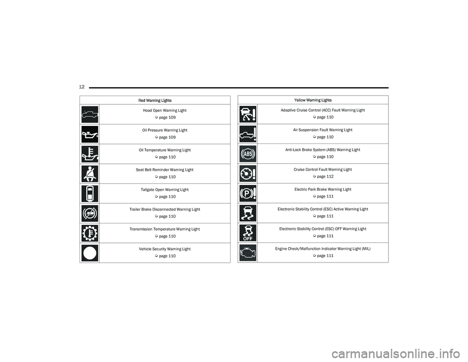
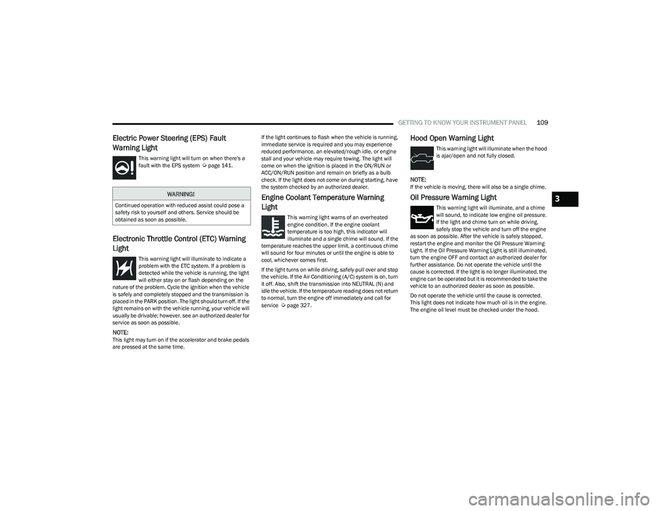
Hood Open Warning Light
Úpage 109
Oil Pressure Warning Light
Úpage 109
Oil Temperature Warning Light
Úpage 110
Seat Belt Reminder Warning Light
Úpage 110
Tailgate Open Warning Light
Úpage 110
Trailer Brake Disconnected Warning Light
Úpage 110
Transmission Temperature Warning Light
Úpage 110
Vehicle Security Warning Light
Úpage 110
Red Warning Lights
Yellow Warning Lights
Adaptive Cruise Control (ACC) Fault Warning Light
Úpage 110
Air Suspension Fault Warning Light
Úpage 110
Anti-Lock Brake System (ABS) Warning Light
Úpage 110
Cruise Control Fault Warning Light
Úpage 112
Electric Park Brake Warning Light
Úpage 111
Electronic Stability Control (ESC) Active Warning Light
Úpage 111
Electronic Stability Control (ESC) OFF Warning Light
Úpage 111
Engine Check/Malfunction Indicator Warning Light (MIL)
Úpage 111
23_DT_OM_EN_USC_t.book Page 12
Page 21 of 416

GETTING TO KNOW YOUR VEHICLE19
Programming And Requesting Additional
Key Fobs
Programming the key fob may be performed by an
authorized dealer.
NOTE:
Once a key fob is programmed to a vehicle, it cannot be
repurposed and reprogrammed to another vehicle.
Only key fobs that are programmed to the vehicle elec -
tronics can be used to start and operate the vehicle. Duplication of key fobs may be performed at an authorized
dealer. This procedure consists of programming a blank
key fob to the vehicle electronics. A blank key fob is one
that has never been programmed.
NOTE:
When having the Sentry Key Immobilizer system
serviced, bring all vehicle keys with you to an autho -
rized dealer.
Keys must be ordered to the correct key cut to match
the vehicle locks.
SENTRY KEY
The Sentry Key Immobilizer system prevents unauthorized
vehicle operation by disabling the engine. The system
does not need to be armed or activated. Operation is
automatic, regardless of whether the vehicle is locked or
unlocked.
The system uses a key fob, keyless push button ignition
and a Radio Frequency (RF) receiver to prevent
unauthorized vehicle operation. Therefore, only key fobs
that are programmed to the vehicle can be used to start
and operate the vehicle. The system cannot reprogram a
key fob obtained from another vehicle. After placing the ignition in the ON/RUN position, the
Vehicle Security Light will turn on for three seconds for a
bulb check. If the light remains on after the bulb check, it
indicates that there is a problem with the electronics.
In addition, if the light begins to flash after the bulb check,
it indicates that someone attempted to start the engine
with an invalid key fob. In the event that a valid key fob is
used to start the engine but there is an issue with the
vehicle electronics, the engine will start and shut off after
two seconds.
If the Vehicle Security Light turns on during normal vehicle
operation (vehicle running for longer than 10 seconds), it
indicates that there is a fault in the electronics. Should
this occur, have the vehicle serviced as soon as possible
by an authorized dealer.
All of the key fobs provided with your new vehicle have
been programmed to the vehicle electronics
Úpage 402.
NOTE:A key fob that has not been programmed is also
considered an invalid key.
WARNING!
The integrated key fob contains a coin cell battery.
Do not ingest the battery; there is a chemical burn
hazard. If the coin cell battery is swallowed, it can
cause severe internal burns in just two hours and
can lead to death.
If you think a battery may have been swallowed or
placed inside any part of the body, seek immediate
medical attention.
Keep new and used batteries away from children.
If the battery compartment does not close securely,
stop using the product and keep it away from
children.
WARNING!
Always remove the key fobs from the vehicle and lock
all doors when leaving the vehicle unattended.
For vehicles equipped with Keyless Enter ‘n Go™
Ignition, always remember to place the ignition in the
OFF position when exiting the vehicle.
CAUTION!
The Sentry Key Immobilizer system is not compatible
with some aftermarket Remote Start systems. Use of
these systems may result in vehicle starting problems
and loss of security protection.
2
23_DT_OM_EN_USC_t.book Page 19
Page 30 of 416
28GETTING TO KNOW YOUR VEHICLE
NOTE:
When the Child-Protection Door Lock system is
engaged, the door can be opened only by using the
outside door handle even though the inside door lock
is in the unlocked position.
After disengaging the Child-Protection Door Lock
system, always test the door from the inside to make
certain it is in the unlocked position.
After engaging the Child-Protection Door Lock system,
always test the door from the inside to make certain it
is in the locked position.
For emergency exit with the system engaged, pull up on
the door lock knob (unlocked position), lower the
window, and open the door with the outside door
handle.
NOTE:Always use this device when carrying children. After
engaging the Child-Protection Door Lock system on both
rear doors, check for effective engagement by trying to
open a door with the internal handle. Once the
Child-Protection Door Lock system is engaged, it is impos -
sible to open the doors from inside the vehicle. Before
getting out of the vehicle, be sure to check that there is no
one left inside.
STEERING WHEEL
TILT/TELESCOPING STEERING COLUMN
This feature allows you to tilt the steering column upward
or downward. It also allows you to lengthen or shorten the
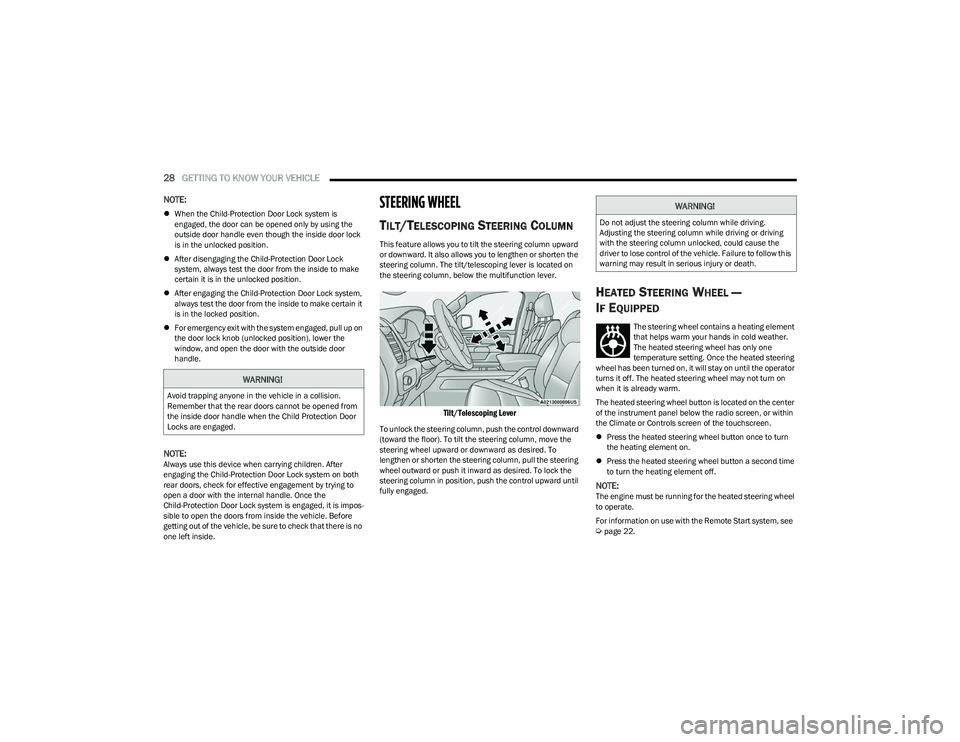
steering column. The tilt/telescoping lever is located on
the steering column, below the multifunction lever.
Tilt/Telescoping Lever
To unlock the steering column, push the control downward
(toward the floor). To tilt the steering column, move the
steering wheel upward or downward as desired. To
lengthen or shorten the steering column, pull the steering
wheel outward or push it inward as desired. To lock the
steering column in position, push the control upward until
fully engaged.
HEATED STEERING WHEEL —
I
F EQUIPPED
The steering wheel contains a heating element
that helps warm your hands in cold weather.
The heated steering wheel has only one
temperature setting. Once the heated steering
wheel has been turned on, it will stay on until the operator
turns it off. The heated steering wheel may not turn on
when it is already warm.
The heated steering wheel button is located on the center
of the instrument panel below the radio screen, or within
the Climate or Controls screen of the touchscreen.
Press the heated steering wheel button once to turn
the heating element on.
Press the heated steering wheel button a second time
to turn the heating element off.
NOTE:The engine must be running for the heated steering wheel
to operate.
For information on use with the Remote Start system, see
Úpage 22.
WARNING!
Avoid trapping anyone in the vehicle in a collision.
Remember that the rear doors cannot be opened from
the inside door handle when the Child Protection Door
Locks are engaged.
WARNING!
Do not adjust the steering column while driving.
Adjusting the steering column while driving or driving
with the steering column unlocked, could cause the
driver to lose control of the vehicle. Failure to follow this
warning may result in serious injury or death.
23_DT_OM_EN_USC_t.book Page 28
Page 100 of 416
98GETTING TO KNOW YOUR INSTRUMENT PANEL
PREMIUM INSTRUMENT CLUSTER
D
ESCRIPTIONS — GASOLINE
1. Temperature Gauge
The temperature gauge shows engine coolant
temperature. Any reading within 203°F - 230°F
(95°C - 110°C) indicates that the engine cooling
system is operating satisfactorily.
The pointer will likely indicate a higher tempera -
ture when driving in hot weather, up mountain
grades, or when towing a trailer. It should not be
allowed to exceed the upper limits of the normal
operating range. 2. Speedometer
Indicates vehicle speed.
3. Fuel Gauge The pointer shows the level of fuel in the fuel tank
when the Keyless Push Button Ignition is in the
ON/RUN position.
The fuel pump symbol points to the
side of the vehicle where the fuel door
is located.
4. Tachometer Indicates the engine speed in revolutions per
minute (RPM x 1000).
5. Instrument Cluster Display The instrument cluster display features a driver
interactive display
Úpage 98.
NOTE:The hard telltales will illuminate for a bulb check when the
ignition is first cycled.
INSTRUMENT CLUSTER DISPLAY
Depending on your vehicles trim level, features and
options may vary.
Your vehicle will be equipped with an instrument cluster
display, which offers useful information to the driver. With
the ignition in the OFF mode, opening/closing of a door will
activate the display for viewing, and display the total miles,
or kilometers, in the odometer. Your instrument cluster
display is designed to display important information about
your vehicle’s systems and features. Using a driver interactive display located on the
instrument panel, your instrument cluster display can
show you how systems are working and give you warnings
when they are not. The steering wheel mounted controls
allow you to scroll through the main menus and
submenus. You can access the specific information you
want and make selections and adjustments.
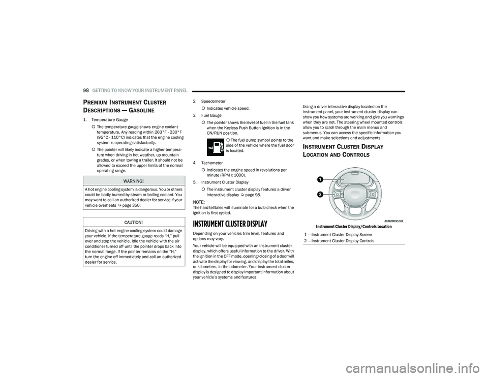
INSTRUMENT CLUSTER DISPLAY
L
OCATION AND CONTROLS
Instrument Cluster Display/Controls Location
WARNING!
A hot engine cooling system is dangerous. You or others
could be badly burned by steam or boiling coolant. You
may want to call an authorized dealer for service if your
vehicle overheats
Úpage 350.
CAUTION!
Driving with a hot engine cooling system could damage
your vehicle. If the temperature gauge reads “H,” pull
over and stop the vehicle. Idle the vehicle with the air
conditioner turned off until the pointer drops back into
the normal range. If the pointer remains on the “H,”
turn the engine off immediately and call an authorized
dealer for service.1 — Instrument Cluster Display Screen
2 — Instrument Cluster Display Controls
23_DT_OM_EN_USC_t.book Page 98
Page 109 of 416

GETTING TO KNOW YOUR INSTRUMENT PANEL107
NOTE:
The charging system is independent from load reduc -
tion. The charging system performs a diagnostic on the
charging system continuously.
If the Battery Charge Warning Light is on it may indicate
a problem with the charging system
Úpage 108.
The electrical loads that may be switched off (if equipped),
and vehicle functions which can be affected by load
reduction:
Heated Seats / Vented Seats / Heated Wheel
Rear Defroster And Heated Mirrors
HVAC System
115 Volts AC Power Inverter System
Audio and Telematics System
Loss of the battery charge may indicate one or more of the
following conditions:
The charging system cannot deliver enough electrical
power to the vehicle system because the electrical
loads are larger than the capability of charging system.
The charging system is still functioning properly.
Turning on all possible vehicle electrical loads
(e.g. HVAC to max settings, exterior and interior lights,
overloaded power outlets +12 Volts, 115 Volts AC, USB
ports) during certain driving conditions (city driving,
towing, frequent stopping).
Installing options like additional lights, upfitter
electrical accessories, audio systems, alarms and
similar devices.
Unusual driving cycles (short trips separated by long
parking periods).
The vehicle was parked for an extended period of time
(weeks, months).
The battery was recently replaced and was not charged
completely.
The battery was discharged by an electrical load left on
when the vehicle was parked.
The battery was used for an extended period with the
engine not running to supply radio, lights, chargers,
+12 Volt portable appliances like vacuum cleaners,
game consoles and similar devices.
What to do when an electrical load reduction action
message is present (“Battery Saver On” or “Battery Saver
Mode”)
During a trip:
Reduce power to unnecessary loads if possible:
Turn off redundant lights (interior or exterior).
Check what may be plugged in to power outlets
+12 Volts, 115 Volts AC, USB ports.
Check HVAC settings (blower, temperature).
Check the audio settings (volume). After a trip:
Check if any aftermarket equipment was installed
(additional lights, upfitter electrical accessories, audio
systems, alarms) and review specifications if any
(load and Ignition Off Draw currents).
Evaluate the latest driving cycles (distance, driving
time and parking time).
The vehicle should have service performed if the
message is still present during consecutive trips and
the evaluation of the vehicle and driving pattern did not
help to identify the cause.
WARNING LIGHTS AND MESSAGES
The warning/indicator lights will illuminate in the
instrument panel together with a dedicated message
and/or acoustic signal when applicable. These indications
are indicative and precautionary and as such must not be
considered as exhaustive and/or alternative to the
information contained in the Owner’s Manual, which you
are advised to read carefully in all cases. Always refer to
the information in this chapter in the event of a failure
indication. All active telltales will display first if applicable.
The system check menu may appear different based upon
equipment options and current vehicle status. Some
telltales are optional and may not appear.
3
23_DT_OM_EN_USC_t.book Page 107
Page 110 of 416

108GETTING TO KNOW YOUR INSTRUMENT PANEL
RED WARNING LIGHTS
Air Bag Warning Light
This warning light will illuminate to indicate a
fault with the air bag, and will turn on for four to
eight seconds as a bulb check when the
ignition is placed in the ON/RUN or ACC/ON/
RUN position. This light will illuminate with a single chime
when a fault with the air bag has been detected, it will stay
on until the fault is cleared. If the light is either not on
during startup, stays on, or turns on while driving, have the
system inspected at an authorized dealer as soon as
possible.
Brake Warning Light
This warning light monitors various brake
functions, including brake fluid level and
parking brake application. If the brake light
turns on it may indicate that the parking brake
is applied, that the brake fluid level is low, or that there is
a problem with the Anti-Lock Brake System reservoir.
If the light remains on when the parking brake has been
disengaged, and the fluid level is at the full mark on the
master cylinder reservoir, it indicates a possible brake
hydraulic system malfunction or that a problem with the
Brake Booster has been detected by the Anti-Lock Brake
System (ABS) / Electronic Stability Control (ESC) system.
In this case, the light will remain on until the condition has
been corrected. If the problem is related to the brake
booster, the ABS pump will run when applying the brake,
and a brake pedal pulsation may be felt during each stop. The dual brake system provides a reserve braking capacity
in the event of a failure to a portion of the hydraulic
system. A leak in either half of the dual brake system is
indicated by the Brake Warning Light, which will turn on
when the brake fluid level in the master cylinder has
dropped below a specified level.
The light will remain on until the cause is corrected.
NOTE:The light may flash momentarily during sharp cornering
maneuvers, which change fluid level conditions. The
vehicle should have service performed, and the brake
fluid level checked.
If brake failure is indicated, immediate repair is necessary.
Vehicles equipped with the Anti-Lock Brake System (ABS)
are also equipped with Electronic Brake Force Distribution
(EBD). In the event of an EBD failure, the Brake Warning
Light will turn on along with the ABS Light. Immediate
repair to the ABS system is required.
Operation of the Brake Warning Light can be checked by
turning the ignition switch from the OFF position to the
ON/RUN position. The light should illuminate for
approximately two seconds.
The light should then turn off unless the parking brake is
applied or a brake fault is detected. If the light does not
illuminate, have the light inspected by an authorized
dealer.
The light also will turn on when the parking brake is
applied with the ignition switch in the ON/RUN position.
NOTE:This light shows only that the parking brake is applied.
It does not show the degree of brake application.
Battery Charge Warning Light
This warning light will illuminate when the
battery is not charging properly. If it stays on
while the engine is running, there may be a
malfunction with the charging system. Contact
an authorized dealer as soon as possible.
This indicates a possible problem with the electrical
system or a related component.
Door Open Warning Light
This indicator will illuminate when a door is
ajar/open and not fully closed.
NOTE:If the vehicle is moving there will also be a single chime.
WARNING!
Driving a vehicle with the red brake light on is
dangerous. Part of the brake system may have failed. It
will take longer to stop the vehicle. You could have a
collision. Have the vehicle checked immediately.
23_DT_OM_EN_USC_t.book Page 108
Page 111 of 416
GETTING TO KNOW YOUR INSTRUMENT PANEL109
Electric Power Steering (EPS) Fault
Warning Light
This warning light will turn on when there's a
fault with the EPS system Úpage 141.
Electronic Throttle Control (ETC) Warning
Light
This warning light will illuminate to indicate a
problem with the ETC system. If a problem is
detected while the vehicle is running, the light
will either stay on or flash depending on the
nature of the problem. Cycle the ignition when the vehicle
is safely and completely stopped and the transmission is
placed in the PARK position. The light should turn off. If the
light remains on with the vehicle running, your vehicle will
usually be drivable; however, see an authorized dealer for
service as soon as possible.
NOTE:This light may turn on if the accelerator and brake pedals
are pressed at the same time. If the light continues to flash when the vehicle is running,
immediate service is required and you may experience
reduced performance, an elevated/rough idle, or engine
stall and your vehicle may require towing. The light will
come on when the ignition is placed in the ON/RUN or
ACC/ON/RUN position and remain on briefly as a bulb
check. If the light does not come on during starting, have
the system checked by an authorized dealer.
Engine Coolant Temperature Warning
Light
This warning light warns of an overheated
engine condition. If the engine coolant
temperature is too high, this indicator will
illuminate and a single chime will sound. If the
temperature reaches the upper limit, a continuous chime
will sound for four minutes or until the engine is able to
cool, whichever comes first.
If the light turns on while driving, safely pull over and stop
the vehicle. If the Air Conditioning (A/C) system is on, turn
it off. Also, shift the transmission into NEUTRAL (N) and
idle the vehicle. If the temperature reading does not return
to normal, turn the engine off immediately and call for
service
Úpage 327.
Hood Open Warning Light
This warning light will illuminate when the hood
is ajar/open and not fully closed.
NOTE:If the vehicle is moving, there will also be a single chime.
Oil Pressure Warning Light
This warning light will illuminate, and a chime
will sound, to indicate low engine oil pressure.
If the light and chime turn on while driving,
safely stop the vehicle and turn off the engine
as soon as possible. After the vehicle is safely stopped,
restart the engine and monitor the Oil Pressure Warning
Light. If the Oil Pressure Warning Light is still illuminated,
turn the engine OFF and contact an authorized dealer for
further assistance. Do not operate the vehicle until the
cause is corrected. If the light is no longer illuminated, the
engine can be operated but it is recommended to take the
vehicle to an authorized dealer as soon as possible.
Do not operate the vehicle until the cause is corrected.
This light does not indicate how much oil is in the engine.
The engine oil level must be checked under the hood.
WARNING!
Continued operation with reduced assist could pose a
safety risk to yourself and others. Service should be
obtained as soon as possible.3
23_DT_OM_EN_USC_t.book Page 109
Page 113 of 416

GETTING TO KNOW YOUR INSTRUMENT PANEL111
Electric Park Brake Warning Light
This warning light will illuminate to indicate the
Electric Park Brake is not functioning properly
and service is required. Contact an authorized
dealer.
Electronic Stability Control (ESC) Active
Warning Light — If Equipped
This warning light will indicate when the ESC
system is Active. The ESC Indicator Light in the
instrument cluster will come on when the
ignition is placed in the ON/RUN or ACC/ON/
RUN position, and when ESC is activated. It should go out
with the engine running. If the ESC Indicator Light comes
on continuously with the engine running, a malfunction
has been detected in the ESC system. If this warning light
remains on after several ignition cycles, and the vehicle
has been driven several miles (kilometers) at speeds
greater than 30 mph (48 km/h), see an authorized dealer
as soon as possible to have the problem diagnosed and
corrected.
The ESC OFF Indicator Light and the ESC Indicator Light
come on momentarily each time the ignition is placed
in the ON/RUN or ACC/ON/RUN position.
The ESC system will make buzzing or clicking sounds
when it is active. This is normal; the sounds will stop
when ESC becomes inactive.
This light will come on when the vehicle is in an ESC
event.
Electronic Stability Control (ESC) OFF
Warning Light — If Equipped
This warning light indicates the ESC is off.
Each time the ignition is turned to ON/RUN or
ACC/ON/RUN, the ESC system will be on, even
if it was turned off previously.
Service LaneSense Warning Light —
If Equipped
This warning light will illuminate when the
LaneSense system is not operating and
requires service. Please contact an authorized
dealer.
Low Fuel Warning Light
When the fuel level is less than a quarter tank,
and the Distance to Empty is less than
50 miles, this light will turn on and remain on
until fuel is added.
A single warning chime will sound with Low Fuel Warning.
Low Washer Fluid Warning Light —
If Equipped
This warning light will illuminate when the
windshield washer fluid is low.
Engine Check/Malfunction Indicator
Warning Light (MIL)
The MIL is a part of an Onboard Diagnostic
System called OBD II that monitors engine and
automatic transmission control systems. This
warning light will illuminate when the ignition is
in the ON/RUN position before engine start. If the bulb
does not come on when turning the ignition switch from
OFF to ON/RUN, have the condition checked promptly.
Certain conditions, such as a loose or missing gas cap,
poor quality fuel, etc., may illuminate the light after engine
start. The vehicle should be serviced if the light stays on
through several typical driving styles. In most situations,
the vehicle will drive normally and will not require towing.
When the engine is running, the MIL may flash to alert
serious conditions that could lead to immediate loss of
power or severe catalytic converter damage. The vehicle
should be serviced by an authorized dealer as soon as
possible if this occurs.
WARNING!
A malfunctioning catalytic converter can reach higher
temperatures than in normal operating conditions. This
can cause a fire if you drive slowly or park over
flammable substances such as dry plants, wood,
cardboard, etc. This could result in death or serious
injury to the driver, occupants or others.
3
23_DT_OM_EN_USC_t.book Page 111
Page 119 of 416

GETTING TO KNOW YOUR INSTRUMENT PANEL117
EMISSIONS INSPECTION AND
MAINTENANCE PROGRAMS
In some localities, it may be a legal requirement to pass an
inspection of your vehicle's emissions control system.
Failure to pass could prevent vehicle registration.
For states that require an Inspection and
Maintenance (I/M), this check verifies the
Malfunction Indicator Light (MIL) is functioning
and is not on when the engine is running, and
that the OBD II system is ready for testing.
Normally, the OBD II system will be ready. The OBD II
system may not be ready if your vehicle was recently
serviced, recently had a depleted battery or a battery
replacement. If the OBD II system should be determined
not ready for the I/M test, your vehicle may fail the test. Your vehicle has a simple ignition actuated test, which you
can use prior to going to the test station. To check if your
vehicle's OBD II system is ready, you must do the following:
1. Cycle the ignition switch to the ON position, but do
not crank or start the engine.
NOTE:If you crank or start the engine, you will have to start this
test over.
2. As soon as you cycle the ignition switch to the ON position, you will see the Malfunction Indicator Light
(MIL) symbol come on as part of a normal bulb check.
3. Approximately 15 seconds later, one of two things will happen:
The MIL will flash for about 10 seconds and then
return to being fully illuminated until you turn OFF
the ignition or start the engine. This means that
your vehicle's OBD II system is not ready and you
should not proceed to the I/M station.
The MIL will not flash at all and will remain fully illu -
minated until you place the ignition in the off posi -
tion or start the engine. This means that your
vehicle's OBD II system is ready and you can
proceed to the I/M station. If your OBD II system is
not ready, you should see an
authorized dealer or repair facility. If your vehicle was
recently serviced or had a battery failure or replacement,
you may need to do nothing more than drive your vehicle
as you normally would in order for your OBD II system to
update. A recheck with the approved test routine may then
indicate that the system is now ready.
Regardless of whether your vehicle's OBD II system is
ready or not, if the MIL is illuminated during normal vehicle
operation you should have your vehicle serviced before
going to the I/M station. The I/M station can fail your
vehicle because the MIL is on with the engine running.
3
23_DT_OM_EN_USC_t.book Page 117