fuse RAM 1500 2023 Owners Manual
[x] Cancel search | Manufacturer: RAM, Model Year: 2023, Model line: 1500, Model: RAM 1500 2023Pages: 416, PDF Size: 20.59 MB
Page 8 of 416

6
SAFETY
SAFETY FEATURES........................................................... 262
Anti-Lock Brake System (ABS) ................................. 262Rear Seat Reminder Alert (RSRA) ............................ 263
Electronic Brake Control (EBC) System .................. 263
AUXILIARY DRIVING SYSTEMS ...................................... 269 Blind Spot Monitoring (BSM) —
If Equipped ............................................................... 269
Forward Collision Warning (FCW) With
Mitigation — If Equipped ........................................... 274
Tire Pressure Monitoring System (TPMS) ............... 277
OCCUPANT RESTRAINT SYSTEMS ................................ 282 Occupant Restraint Systems Features ................... 282Important Safety Precautions .................................. 282Seat Belt Systems .................................................... 282
Supplemental Restraint Systems (SRS) .................. 288Child Restraints ........................................................ 298
SAFETY TIPS .................................................................... 311 Transporting Passengers .......................................... 311
Transporting Pets ..................................................... 311
Connected Vehicles .................................................. 311
Safety Checks You Should Make Inside
The Vehicle ............................................................... 311
Periodic Safety Checks You Should Make
Outside The Vehicle .................................................. 312
Exhaust Gas ............................................................. 313Carbon Monoxide Warnings .................................... 313
IN CASE OF EMERGENCY
HAZARD WARNING FLASHERS .................................... 314
ASSIST AND SOS SYSTEM — IF EQUIPPED ................. 314
JACKING AND TIRE CHANGING .................................... 317 Preparations For Jacking.......................................... 317Jack Location ............................................................ 318
Removal Of Jack And Tools ...................................... 318
Removing The Spare Tire ......................................... 319
Jacking Instructions.................................................. 321To Stow The Flat Or Spare ....................................... 323
Reinstalling The Jack And Tools .............................. 324
JUMP STARTING ............................................................. 325 Preparations For Jump Start .................................... 325Jump Starting Procedure.......................................... 325
REFUELING IN EMERGENCY........................................... 326
IF YOUR ENGINE OVERHEATS ....................................... 327
MANUAL PARK RELEASE ............................................... 328
FREEING A STUCK VEHICLE .......................................... 329
TOWING A DISABLED VEHICLE ..................................... 330 Two-Wheel Drive Models .......................................... 331Four-Wheel Drive Models ......................................... 331
Emergency Tow Hooks — If Equipped ..................... 332
ENHANCED ACCIDENT RESPONSE SYSTEM
(EARS) .............................................................................. 332
EVENT DATA RECORDER (EDR) ..................................... 332
SERVICING AND MAINTENANCE
SCHEDULED SERVICING ................................................. 333 Maintenance Plan ..................................................... 334
ENGINE COMPARTMENT ................................................337 3.6L Engine With Stop/Start ................................... 337
5.7L Engine Without Stop/Start ............................... 3385.7L Engine With Stop/Start .................................... 339
Checking Oil Level ..................................................... 340Adding Washer Fluid ................................................ 340
Maintenance-Free Battery ....................................... 340Pressure Washing ..................................................... 341
VEHICLE MAINTENANCE ................................................. 341 Engine Oil .................................................................. 341
Engine Oil Filter ........................................................ 342
Engine Air Cleaner Filter .......................................... 342
Air Conditioner Maintenance ................................... 344
Accessory Drive Belt Inspection ............................... 346Body Lubrication ....................................................... 347
Windshield Wiper Blades ......................................... 347
Exhaust System ........................................................ 348
Cooling System ......................................................... 349
Brake System ........................................................... 352
Automatic Transmission .......................................... 353
Rear Axle And 4x4 Front Driving Axle
Fluid Level ................................................................. 353
Transfer Case ........................................................... 354
Fuses .......................................................................... 354Bulb Replacement .................................................... 365
23_DT_OM_EN_USC_t.book Page 6
Page 68 of 416

66GETTING TO KNOW YOUR VEHICLE
NOTE:Charge unsupported devices with the Charge Only USB
ports. If an unsupported device is plugged into a Media
USB port, a message will display on the touchscreen that
the device is not supported by the system.
Plugging in a phone or another USB device may cause the
connection to a previous device to be lost.
If equipped, your vehicle may also contain a USB port
located on the top tray of the vehicle’s center console.
If equipped, two Mini-USB ports (Type C), two Standard
USB ports (Type A), and one AUX port may be located to the
left of the center stack, just below the climate controls.
Center Console USB/AUX Media Hub
Some USB ports support media and charging. You can use
features, such as Apple CarPlay®, Android Auto™,
Pandora®, and others while charging your phone.
NOTE:Plugging in a phone or another USB device may cause the
connection to a previous device to be lost.
For further information, refer to the Uconnect Radio
Instruction Manual or visit UconnectPhone.com.
ELECTRICAL POWER OUTLETS
The auxiliary 12 Volt (13 Amp) power outlet can provide
power for in-cab accessories designed for use with the
standard “cigarette lighter” style plug. The 12 Volt power
outlets and 5 Volt (2.5 Amp) USB Port (Charge Only) have
a cap attached to the outlet indicating “12V DC”, together
with either a key symbol, battery symbol, or USB symbol.
An auxiliary power outlet can be found in the tray on top of
the center stack. This power outlet works when the ignition
is in the ON/RUN, ACC, or OFF position.
Power Outlet — Top Of Center Stack
Power Outlet Fuse Locations
1 — Standard USB Type A Ports
2 — Mini-USB Type C Ports
3 — AUX Port
CAUTION!
Do not exceed the maximum power of 160 Watts
(13 Amps) at 12 Volts. If the 160 Watts (13 Amps)
power rating is exceeded, the fuse protecting the
system will need to be replaced.
Power outlets are designed for accessory plugs only.
Do not insert any other object in the power outlets as
this will damage the outlet and blow the fuse.
Improper use of the power outlet can cause damage
not covered by your New Vehicle Limited Warranty.
1 — F54 Fuse 20 A Yellow Power Outlet Battery Fed
Position
2 — F54 Fuse 20 A Yellow Power Outlet Ignition Fed
Position
3 — F48 Fuse 10 A Red Port Power or Rear USB
(Charge Only)
23_DT_OM_EN_USC_t.book Page 66
Page 327 of 416

IN CASE OF EMERGENCY325
JUMP STARTING
If your vehicle has a discharged battery, it can be jump
started using a set of jumper cables and a battery in
another vehicle, or by using a portable battery booster
pack. Jump starting can be dangerous if done improperly,
so please follow the procedures in this section carefully.
NOTE:When using a portable battery booster pack, follow the
manufacturer's operating instructions and precautions.
PREPARATIONS FOR JUMP START
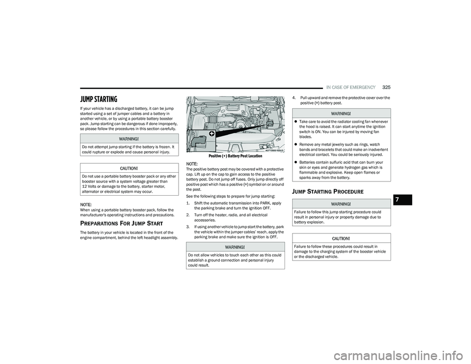
The battery in your vehicle is located in the front of the
engine compartment, behind the left headlight assembly.
Positive (+) Battery Post Location
NOTE:
The positive battery post may be covered with a protective
cap. Lift up on the cap to gain access to the positive
battery post. Do not jump off fuses. Only jump directly off
positive post which has a positive (+) symbol on or around
the post.
See the following steps to prepare for jump starting:
1. Shift the automatic transmission into PARK, apply the parking brake and turn the ignition OFF.
2. Turn off the heater, radio, and all electrical accessories.
3. If using another vehicle to jump start the battery, park the vehicle within the jumper cables’ reach, apply the
parking brake and make sure the ignition is OFF. 4. Pull upward and remove the protective cover over the
positive (+) battery post.
JUMP STARTING PROCEDURE
WARNING!
Do not attempt jump starting if the battery is frozen. It
could rupture or explode and cause personal injury.
CAUTION!
Do not use a portable battery booster pack or any other
booster source with a system voltage greater than
12 Volts or damage to the battery, starter motor,
alternator or electrical system may occur.
WARNING!
Do not allow vehicles to touch each other as this could
establish a ground connection and personal injury
could result.
WARNING!
Take care to avoid the radiator cooling fan whenever
the hood is raised. It can start anytime the ignition
switch is ON. You can be injured by moving fan
blades.
Remove any metal jewelry such as rings, watch
bands and bracelets that could make an inadvertent
electrical contact. You could be seriously injured.
Batteries contain sulfuric acid that can burn your
skin or eyes and generate hydrogen gas which is
flammable and explosive. Keep open flames or
sparks away from the battery.
WARNING!
Failure to follow this jump starting procedure could
result in personal injury or property damage due to
battery explosion.
CAUTION!
Failure to follow these procedures could result in
damage to the charging system of the booster vehicle
or the discharged vehicle.
7
23_DT_OM_EN_USC_t.book Page 325
Page 328 of 416

326IN CASE OF EMERGENCY
Connecting The Jumper Cables
1. Connect the positive
(+) end of the jumper cable to
the positive (+)
post of the discharged vehicle.
NOTE:Do not jump off fuses. Only jump directly off positive post.
2. Connect the opposite end of the positive (+) jumper
cable to the positive (+) post of the booster battery.
3. Connect the negative (-) end of the jumper cable to
the negative (-) post of the booster battery.
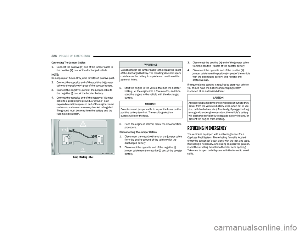
4. Connect the opposite end of the negative (-) jumper
cable to a good engine ground. A “ground” is an
exposed metallic/unpainted part of the engine, frame
or chassis, such as an accessory bracket or large bolt.
The ground must be away from the battery and the
fuel injection system.
Jump Starting Label
5. Start the engine in the vehicle that has the booster battery, let the engine idle a few minutes, and then
start the engine in the vehicle with the discharged
battery.
6. Once the engine is started, follow the disconnection procedure.
Disconnecting The Jumper Cables
1. Disconnect the negative
(-)
end of the jumper cable
from the engine ground of the vehicle with the
discharged battery.
2. Disconnect the opposite end of the negative (-)
jumper cable from the negative (-) post of the booster
battery. 3. Disconnect the positive
(+) end of the jumper cable
from the positive (+) post of the booster battery.
4. Disconnect the opposite end of the positive (+)
jumper cable from the positive (+) post of the vehicle
with the discharged battery, and reinstall the
protective cap.
If frequent jump starting is required to start your vehicle
you should have the battery and charging system
inspected at an authorized dealer.
REFUELING IN EMERGENCY
The vehicle is equipped with a refueling funnel for a
Cap-Less Fuel System. The refueling funnel is located
under the passenger’s seat along with the jack and tools.
If refueling is necessary, while using an approved gas can,
insert the refueling funnel into the filler neck opening.
Take care to open both flappers with the funnel to avoid
spills.
WARNING!
Do not connect the jumper cable to the negative (-) post
of the discharged battery. The resulting electrical spark
could cause the battery to explode and could result in
personal injury.
CAUTION!
Do not connect jumper cable to any of the fuses on the
positive battery terminal. The resulting electrical
current will blow the fuse.
CAUTION!
Accessories plugged into the vehicle power outlets draw
power from the vehicle’s battery, even when not in use
(i.e., cellular devices, etc.). Eventually, if plugged in long
enough without engine operation, the vehicle’s battery
will discharge sufficiently to degrade battery life and/or
prevent the engine from starting.
23_DT_OM_EN_USC_t.book Page 326
Page 339 of 416

SERVICING AND MAINTENANCE337
ENGINE COMPARTMENT
3.6L ENGINE WITH STOP/START
1 — Motor Generator Unit Coolant Reservoir Pressure Cap 6 — Battery
2 — Engine Coolant Reservoir Pressure Cap 7 — Engine Air Cleaner Filter
3 — Engine Oil Dipstick 8 — Washer Fluid Reservoir Cap
4 — Engine Oil Fill 9 — Power Distribution Center (Fuses)
5 — Brake Fluid Reservoir
8
23_DT_OM_EN_USC_t.book Page 337
Page 340 of 416

338SERVICING AND MAINTENANCE
5.7L ENGINE WITHOUT STOP/START
1 — Engine Air Cleaner Filter 6 — Battery
2 — Engine Coolant Pressure Cap 7 — Engine Coolant Reservoir Cap
3 — Engine Oil Fill 8 — Washer Fluid Reservoir Cap
4 — Engine Oil Dipstick 9 — Power Distribution Center (Fuses)
5 — Brake Fluid Reservoir Cap
23_DT_OM_EN_USC_t.book Page 338
Page 341 of 416

SERVICING AND MAINTENANCE339
5.7L ENGINE WITH STOP/START
1 — Engine Air Cleaner Filter 6 — Battery
2 — Engine Coolant Pressure Cap 7 — Engine Coolant Reservoir Cap
3 — Engine Oil Fill 8 — Washer Fluid Reservoir Cap
4 — Engine Oil Dipstick 9 — Power Distribution Center (Fuses)
5 — Brake Fluid Reservoir Cap
8
23_DT_OM_EN_USC_t.book Page 339
Page 356 of 416

354SERVICING AND MAINTENANCE
Drain And Refill
For the proper maintenance intervals Úpage 334.
Lubricant Selection
For further information Úpage 397.
NOTE:The presence of water in the gear lubricant will result in
corrosion and possible failure of differential components.
Operation of the vehicle in water, as may be encountered
in some off-highway types of service, will require draining
and refilling the axle to avoid damage.
Limited-Slip Differentials
Rear axles equipped with a Limited Slip Differential
require that 5 oz. (148 ml) Mopar® Limited Slip Additive
be added to the gear lubricant
Úpage 397. The Mopar®
Limited Slip Additive should be added to the gear lubricant
whenever a fluid change is made to an axle equipped with
a Limited Slip Differential.
NOTE:When refilling a limited slip differential axle which requires
a friction modification additive, the additive should be
added before the gear lubricant to ensure proper
additive fill.
TRANSFER CASE
Fluid Level Check
This fluid level can be checked by removing the filler plug.
The fluid level should be to the bottom edge of the filler
plug hole (or within 1/8 inch of the bottom) with the
vehicle in a level position.
Drain And Refill
For the proper maintenance intervals Úpage 334.
Selection Of Lubricant
Use only the manufacturer recommended fluid Úpage 397.
FUSES
General Information
WARNING!
When replacing a blown fuse, always use an appro -
priate replacement fuse with the same amp rating as
the original fuse. Never replace a fuse with another
fuse of higher amp rating. The use of a fuse with a
rating other than indicated may result in a dangerous
electrical system overload. If a properly rated fuse
continues to blow, it indicates a problem in the circuit
that must be corrected. Never replace a blown fuse
with metal wires or any other material. Do not place
a fuse inside a circuit breaker cavity or vice versa.
Failure to use proper fuses may result in serious
personal injury, fire and/or property damage.
Before replacing a fuse, make sure that the ignition
is off and that all the other services are switched off
and/or disengaged.
If the replaced fuse blows again, contact an
authorized dealer.
If a general protection fuse for safety systems (air
bag system, braking system), power unit systems
(engine system, transmission system) or steering
system blows, contact an authorized dealer.
23_DT_OM_EN_USC_t.book Page 354
Page 357 of 416

SERVICING AND MAINTENANCE355
The fuses protect electrical systems against excessive
current.
When a device does not work, you must check the fuse
element inside the blade fuse for a break/melt.
Also, please be aware that using power outlets for
extended periods of time with the engine off may result in
vehicle battery discharge.
Blade Fuses
Underhood Power Distribution Center
The Power Distribution Center is located in the engine
compartment near the battery. This center contains
cartridge fuses, micro fuses, relays, and circuit breakers.
A description of each fuse and component may be
stamped on the inside cover, otherwise the cavity number
of each fuse is stamped on the inside cover that
corresponds to the following chart.CAUTION!
If it is necessary to wash the engine compartment, take
care not to directly hit the fuse box, and the windshield
wiper motors with water.
1 — Fuse Element
2 — Blade Fuse with a good/functional fuse element
3 — Blade Fuse with a bad/not functional fuse element
(blown fuse)
CAUTION!
When installing the power distribution center cover, it is
important to ensure the cover is properly positioned
and fully latched. Failure to do so may allow water to get
into the power distribution center and possibly result in
an electrical system failure.
8
23_DT_OM_EN_USC_t.book Page 355
Page 359 of 416

SERVICING AND MAINTENANCE357
CavityCartridge Fuse Micro Fuse Description
* If Equipped
F01 –25 Amp ClearFuel Pump Motor / Assy Fuel Tank
F02 ––Spare *
F03 –5 Amp TanMGU *
F04 ––Spare *
F05 ––Spare *
F06 –10 Amp RedOUTPUT TO UPFITTER PDC *
F07 ––Spare *
F08 20 Amp Blue –Trailer Tow Backup
F09 –20 Amp Yellow Trailer Stop / Turn Lamp Left
F10 –20 Amp Yellow Trailer Stop / Turn Lamp Right
F11 –15 Amp BlueID/CLEARANCE LIGHTS *
F12 20 Amp Blue –Trailer Tow Park Lamp
F13 ––Spare *
F14 –10 Amp RedAC Clutch
F15 –5 Amp TanIntelligent Battery Sensor (IBS)
F16 ––Spare *
F17 –20 Amp Yellow Air Suspension
F18 –15 Amp BlueAGS / Rear Axle Cooling Valve / Active Air Dam
F19 ––Spare *
8
23_DT_OM_EN_USC_t.book Page 357