turn signal Ram 2500 2017 User Guide
[x] Cancel search | Manufacturer: RAM, Model Year: 2017, Model line: 2500, Model: Ram 2500 2017Pages: 734, PDF Size: 7.3 MB
Page 148 of 734

Cargo Light With Bed Lights — If Equipped
The cargo light and bed lights (if equipped) are turned on
by pushing on the cargo lights button.
The cargo light and bed lights (if equipped) will also turn
on for approximately 60 seconds when a key fob unlock
button is pushed, as part of the Illuminated Entry feature.
Multifunction Lever
The multifunction lever is located on the left side of the
steering column.
Turn Signals
Move the multifunction lever up or down and the arrows
on each side of the instrument cluster display will flash to
show proper operation of the front and rear turn signal
lights.
NOTE:If either light remains on and does not flash, or
there is a very fast flash rate, check for a defective outside
light bulb. If an indicator fails to light when the lever is
moved, it would suggest that the indicator bulb is defec-
tive.
Cargo Lights Button
Turn Signal Lever
146 UNDERSTANDING THE FEATURES OF YOUR VEHICLE
Page 149 of 734
Lane Change Assist
Tap the lever up or down once, without moving beyond
the detent, and the turn signal (right or left) will flash three
times. Then, the turn signal (right or left) will automatically
turn off.
Flash-To-Pass
You can signal another vehicle with your headlights by
partially pulling the multifunction lever toward the steer-
ing wheel. This will cause the high beam headlights to turn
on until the lever is released.
High/Low Beam Switch
Push the multifunction lever toward the instrument panel
to switch the headlights to high beam. Pulling the multi-
function lever back toward the steering wheel will turn the
low beams back on, or shut the high beams off.
High/Low Beam Switch
3
UNDERSTANDING THE FEATURES OF YOUR VEHICLE 147
Page 181 of 734
3.Without releasing the button proceed with “Program-
ming A Non-Rolling Code” step 2 and follow all remain-
ing steps.
Canadian/Gate Operator Programming
For programming transmitters in Canada/United States
that require the transmitter signals to “time-out” after
several seconds of transmission.
Canadian radio frequency laws require transmitter signals
to time-out (or quit) after several seconds of transmission –
which may not be long enough for HomeLink to pick up
the signal during programming. Similar to this Canadian
law, some U.S. gate operators are designed to time-out in
the same manner.
It may be helpful to unplug the device during the cycling
process to prevent possible overheating of the garage door
or gate motor.
1. Turn the ignition switch to the ON/RUN position.
For vehicle’s equipped with Keyless Enter-N-Go, place the
ignition in the RUN position with the Engine ON. 2. Place the hand - held transmitter 1 to 3 inches (3 to 8 cm)
away from the HomeLink button you wish to program.
3. Push and hold the HomeLink button while you push and release (“cycle”), your hand - held transmitter every
two seconds.
4. Continue to hold both buttons until the instrument cluster display changes from “CHANNEL # TRAIN-
ING” to “CHANNEL # TRAINED,” then release both
buttons.
NOTE: •It may take up to 30 seconds or longer in some cases
for the channel to train.
• If the instrument cluster display shows “DID NOT
TRAIN”, repeat from Step 2.
5. Push and hold the programmed HomeLink button. The instrument cluster display will display “CHANNEL #
TRANSMIT.” If the device is plugged in and activates,
programming is complete.
If you unplugged the garage door opener/device for
programming, plug it back in at this time.3
UNDERSTANDING THE FEATURES OF YOUR VEHICLE 179
Page 242 of 734
7. Temperature Gauge•The temperature gauge shows engine coolant tem-
perature. Any reading within the normal range indi-
cates that the engine cooling system is operating
satisfactorily.
• The gauge pointer will likely indicate a higher tem-
perature when driving in hot weather, up mountain
grades, or when towing a trailer. It should not be
allowed to exceed the upper limits of the normal
operating range.
WARNING!
A hot engine cooling system is dangerous. You or
others could be badly burned by steam or boiling
coolant. You may want to call an authorized dealer for
service if your vehicle overheats. If you decide to look
under the hood yourself, see “Maintaining Your Ve-
hicle”. Follow the warnings under the Cooling System
Pressure Cap paragraph.
CAUTION!
Driving with a hot engine cooling system could dam-
age your vehicle. If the temperature gauge reads “H”
pull over and stop the vehicle. Idle the vehicle with the
air conditioner turned off until the pointer drops back
into the normal range. If the pointer remains on the
“H”, turn the engine off immediately and call an
authorized dealer for service.
WARNING AND INDICATOR LIGHTS
The warning / indicator lights switch on in the instrument
panel together with a dedicated message and/or acoustic
signal when applicable. These indications are indicative
and precautionary and as such must not be considered as
exhaustive and/or alternative to the information contained
in the Owner ’s Manual, which you are advised to read
carefully in all cases. Always refer to the information in this
chapter in the event of a failure indication.
All active telltales will display first if applicable. The
system check menu may appear different based upon
equipment options and current vehicle status. Some tell-
tales are optional and may not appear.
240 UNDERSTANDING YOUR INSTRUMENT PANEL
Page 265 of 734
Turn Signal Indicator Lights
Green TelltaleLight What It Means
Turn Signal Indicator Lights
The instrument cluster directional arrow will flash independently for the left or right turn signal
as selected, as well as the exterior turn signal lamp(s) (front and rear) as selected when the multi-
function lever is moved down (left) or up (right).
NOTE:
•A continuous chime will sound if the vehicle is driven more than 1 mile (1.6 km) with either
turn signal on.
•Check for an inoperative outside light bulb if either indicator flashes at a rapid rate.
Cruise Control Set Indicator Light — If Equipped
Green Telltale
Light What It Means
Cruise Control Set Indicator Light — If Equipped
This light will turn on when the speed control has been set.
4
UNDERSTANDING YOUR INSTRUMENT PANEL 263
Page 273 of 734
The instrument cluster display screens are located in the
center portion of the cluster and consists of eight sections:
1.
Main Screen — The inner ring of the display will illumi-
nate in grey under normal conditions, yellow for non
critical warnings, red for critical warnings, and white for
on demand information.
2.Audio / Phone Information and Submenu Information —
Whenever there are sub-menus available, the position
within the submenus is shown here.
3.Selectable Information (Compass, Temp, Range to Empty,
Trip A, Trip B, Average MPG, Trailer Trip (distance only),
Trailer Brake Gain, Time)
4. Telltales/Indicators
5. Gear Selector Status (PRNDL)
6. Selectable Menu Icons
7. Air Suspension Status – If Equipped
8. 4WD Status
9. Selectable Gauge 2 (Trans Temp, Oil Temp, Oil Life,Trailer Brake, Current MPG)
10. Selectable Gauge 1 (Trans Temp, Oil Temp, Oil Life, Trailer Brake, Current MPG) The instrument cluster display area will normally display
the main menu or the screens of a selected feature of the
main menu. The main display area also displays “pop up”
messages that consist of approximately 60 possible warn-
ing or information messages. These pop up messages fall
into several categories:
•
Five Second Stored Messages
When the appropriate conditions occur, this type of mes-
sage takes control of the main display area for five seconds
and then returns to the previous screen. Most of the
messages of this type are then stored (as long as the
condition that activated it remains active) and can be
reviewed from the “Messages” main menu item. As long as
there is a stored message, an “i” will be displayed in the
instrument cluster display’s compass/outside temp line.
Examples of this message type are “Right Front Turn Signal
Lamp Out” and “Low Tire Pressure.”
• Unstored Messages
This message type is displayed indefinitely or until the
condition that activated the message is cleared. Examples
of this message type are “Turn Signal On” (if a turn signal
is left on) and “Lights On” (if driver leaves the vehicle).
4
UNDERSTANDING YOUR INSTRUMENT PANEL 271
Page 282 of 734
Turn Menu OFF — If Equipped
Push and release therightarrow button to exit the main
menu.
Push and release any instrument cluster display control
button to enter the instrument cluster display main menu
again.
Instrument Cluster Display Messages
• Front Seatbelts Unbuckled
• Driver Seatbelt Unbuckled
• Passenger Seatbelt Unbuckled
• Service Airbag System
• Traction Control Off
• Washer Fluid Low
• Oil Pressure Low
• Oil Change Due
• Fuel Low
• Service Antilock Brake System
• Service Electronic Throttle Control •
Service Power Steering
• Cruise Off
• Cruise Ready
• Cruise Set To XXX MPH
• Tire Pressure Screen With Low Tire(S) “Inflate Tire To
XX”
• Tire Pressure Information System (TPIS)
• Service Tire Pressure System
• Parking Brake Engaged
• Brake Fluid Low
• Service Electronic Braking System
• Engine Temperature Hot
• Battery Voltage Low
• Service Electronic Throttle Control
• Lights On
• Right Turn Signal Light Out
• Left Turn Signal Light Out
280 UNDERSTANDING YOUR INSTRUMENT PANEL
Page 283 of 734

•Turn Signal On
• Sound Horn With Remote Lock: Off; 1st Press; 2nd Press
• Vehicle Not In Park
• Key In Ignition
• Key In Ignition Lights On
• Remote Start Active Key To Run
• Remote Start Active Push Start Button
• Remote Start Aborted Fuel Low
• Remote Start Aborted Too Cold
• Remote Start Aborted Door Open
• Remote Start Aborted Hood Open
• Remote Start Aborted Trunk Open
• Remote Start Aborted Time Expired
• Remote Start Disabled Start To Reset
• Service Airbag System
• Service Airbag Warning Light
• Driver Seatbelt Unbuckled •
Passenger Seatbelt Unbuckled
• Front Seatbelts Unbuckled
• Door Open
• Doors Open
• Gear Not Available
• Shift Not Allowed
• Shift To Neutral Then Drive Or Reverse
• Autostick Unavailable Service Required
• Automatic Unavailable Use Autostick Service Req.
• Transmission Getting Hot Push Brake
• Trans. Hot Stop Safely Shift To Park Wait To Cool
• Transmission Cool Ready To Drive
• Trailer Brake Disconnected
• Service Transmission
• Service Shifter
• Engage Park Brake To Prevent Rolling
• Transmission Too Cold Idle With Engine On
4
UNDERSTANDING YOUR INSTRUMENT PANEL 281
Page 317 of 734
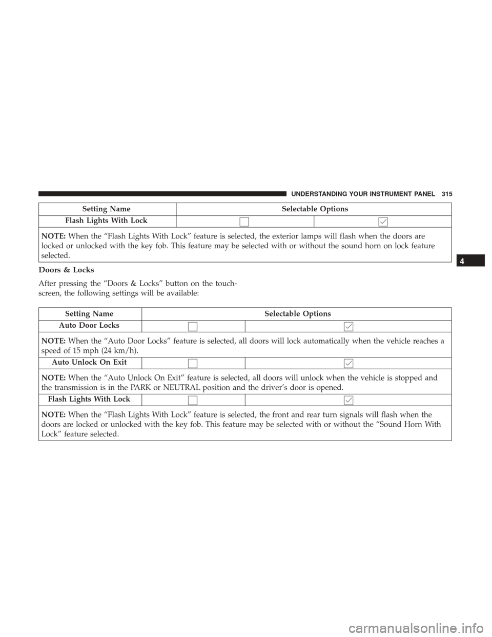
Setting NameSelectable Options
Flash Lights With Lock
NOTE: When the “Flash Lights With Lock” feature is selected, the exterior lamps will flash when the doors are
locked or unlocked with the key fob. This feature may be selected with or without the sound horn on lock feature
selected.
Doors & Locks
After pressing the “Doors & Locks” button on the touch-
screen, the following settings will be available:
Setting Name Selectable Options
Auto Door Locks
NOTE: When the “Auto Door Locks” feature is selected, all doors will lock automatically when the vehicle reaches a
speed of 15 mph (24 km/h).
Auto Unlock On Exit
NOTE: When the “Auto Unlock On Exit” feature is selected, all doors will unlock when the vehicle is stopped and
the transmission is in the PARK or NEUTRAL position and the driver’s door is opened.
Flash Lights With Lock
NOTE: When the “Flash Lights With Lock” feature is selected, the front and rear turn signals will flash when the
doors are locked or unlocked with the key fob. This feature may be selected with or without the “Sound Horn With
Lock” feature selected.
4
UNDERSTANDING YOUR INSTRUMENT PANEL 315
Page 321 of 734
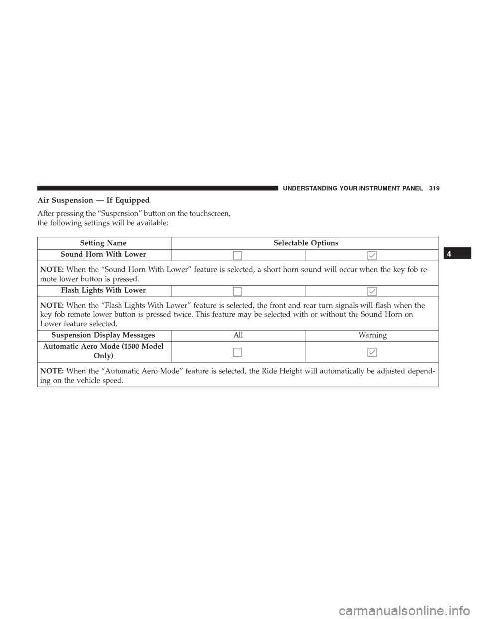
Air Suspension — If Equipped
After pressing the “Suspension” button on the touchscreen,
the following settings will be available:
Setting NameSelectable Options
Sound Horn With Lower
NOTE: When the “Sound Horn With Lower” feature is selected, a short horn sound will occur when the key fob re-
mote lower button is pressed.
Flash Lights With Lower
NOTE: When the “Flash Lights With Lower” feature is selected, the front and rear turn signals will flash when the
key fob remote lower button is pressed twice. This feature may be selected with or without the Sound Horn on
Lower feature selected.
Suspension Display Messages AllWarning
Automatic Aero Mode (1500 Model Only)
NOTE: When the “Automatic Aero Mode” feature is selected, the Ride Height will automatically be adjusted depend-
ing on the vehicle speed.
4
UNDERSTANDING YOUR INSTRUMENT PANEL 319