tire type Ram 2500 2017 Owner's Guide
[x] Cancel search | Manufacturer: RAM, Model Year: 2017, Model line: 2500, Model: Ram 2500 2017Pages: 734, PDF Size: 7.3 MB
Page 538 of 734

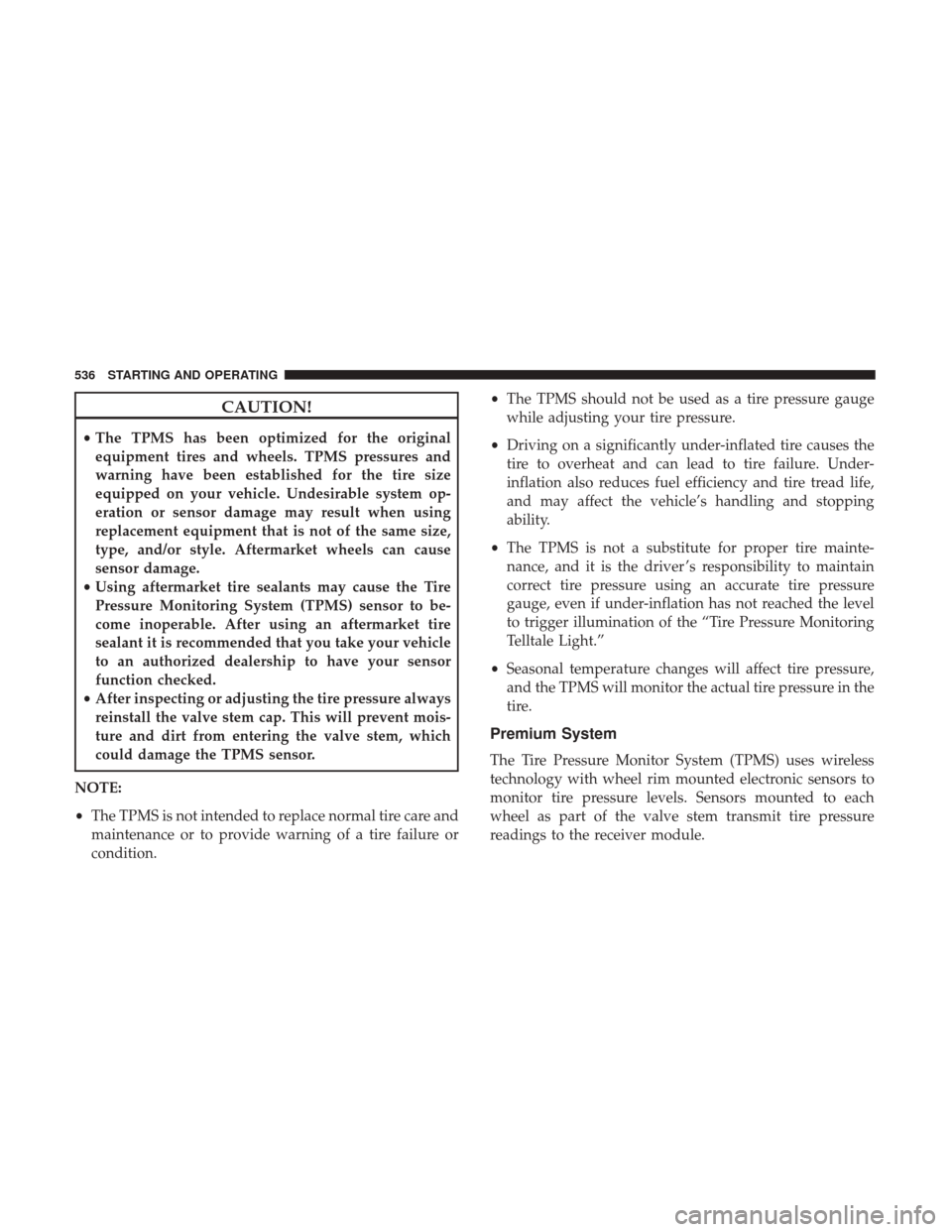
CAUTION!
•The TPMS has been optimized for the original
equipment tires and wheels. TPMS pressures and
warning have been established for the tire size
equipped on your vehicle. Undesirable system op-
eration or sensor damage may result when using
replacement equipment that is not of the same size,
type, and/or style. Aftermarket wheels can cause
sensor damage.
• Using aftermarket tire sealants may cause the Tire
Pressure Monitoring System (TPMS) sensor to be-
come inoperable. After using an aftermarket tire
sealant it is recommended that you take your vehicle
to an authorized dealership to have your sensor
function checked.
• After inspecting or adjusting the tire pressure always
reinstall the valve stem cap. This will prevent mois-
ture and dirt from entering the valve stem, which
could damage the TPMS sensor.
NOTE:
• The TPMS is not intended to replace normal tire care and
maintenance or to provide warning of a tire failure or
condition. •
The TPMS should not be used as a tire pressure gauge
while adjusting your tire pressure.
• Driving on a significantly under-inflated tire causes the
tire to overheat and can lead to tire failure. Under-
inflation also reduces fuel efficiency and tire tread life,
and may affect the vehicle’s handling and stopping
ability.
• The TPMS is not a substitute for proper tire mainte-
nance, and it is the driver ’s responsibility to maintain
correct tire pressure using an accurate tire pressure
gauge, even if under-inflation has not reached the level
to trigger illumination of the “Tire Pressure Monitoring
Telltale Light.”
• Seasonal temperature changes will affect tire pressure,
and the TPMS will monitor the actual tire pressure in the
tire.
Premium System
The Tire Pressure Monitor System (TPMS) uses wireless
technology with wheel rim mounted electronic sensors to
monitor tire pressure levels. Sensors mounted to each
wheel as part of the valve stem transmit tire pressure
readings to the receiver module.
536 STARTING AND OPERATING
Page 553 of 734

The entire vehicle should first be weighed on a commercial
scale to insure that the GVWR has not been exceeded. The
weight on the front and rear of the vehicle should then be
determined separately to be sure that the load is properly
distributed over the front and rear axle. Weighing the
vehicle may show that the GAWR of either the front or rear
axles has been exceeded but the total load is within the
specified GVWR. If so, weight must be shifted from front to
rear or rear to front as appropriate until the specified
weight limitations are met. Store the heavier items down
low and be sure that the weight is distributed equally. Stow
all loose items securely before driving.
Improper weight distributions can have an adverse effect
on the way your vehicle steers and handles and the way
the brakes operate.
CAUTION!
Do not load your vehicle any heavier than the GVWR
or the maximum front and rear GAWR. If you do, parts
on your vehicle can break, or it can change the way
your vehicle handles. This could cause you to lose
control. Also overloading can shorten the life of your
vehicle.
TRAILER TOWING
In this section you will find safety tips and information on
limits to the type of towing you can reasonably do with
your vehicle. Before towing a trailer, carefully review this
information to tow your load as efficiently and safely as
possible.
To maintain the New Vehicle Limited Warranty coverage,
follow the requirements and recommendations in this
manual concerning vehicles used for trailer towing.
Common Towing Definitions
The following trailer towing related definitions will assist
you in understanding the following information:
Gross Vehicle Weight Rating (GVWR)
The GVWR is the total allowable weight of your vehicle.
This includes driver, passengers, cargo and tongue weight.
The total load must be limited so that you do not exceed
the GVWR. Refer to “Vehicle Loading/Vehicle Certification
Label” in “Starting And Operating” for further informa-
tion.
5
STARTING AND OPERATING 551
Page 561 of 734

Trailer Towing Weights (Maximum Trailer Weight
Ratings)
NOTE:For additional trailer towing information (maxi-
mum trailer weight ratings) refer to the following website
addresses:
• ramtrucks.com/en/towing_guide/
• ramtruck.ca (Canada)
• rambodybuilder.com
Trailer And Tongue Weight
Never exceed the maximum tongue weight stamped on
your trailer hitch or the weights specified in the informa-
tion that can be found under “Trailer Towing Weights
(Maximum Trailer Weight Ratings)”.
Consider the following items when computing the weight
on the rear axle of the vehicle:
•The tongue weight of the trailer
• The weight of any other type of cargo or equipment put
in or on your vehicle
• The weight of the driver and all passengers NOTE:
Remember that everything put into or on the trailer
adds to the load on your vehicle. Also, additional factory-
installed options or dealer-installed options must be con-
sidered as part of the total load on your vehicle. Refer to
“Tire Safety Information/Tire and Loading Information
Placard” in “Starting And Operating” for further informa-
tion.
Towing Requirements
To promote proper break-in of your new vehicle drivetrain
components the following guidelines are recommended:
CAUTION!
• Do not tow a trailer at all during the first 500 miles
(805 km) the new vehicle is driven. The engine, axle
or other parts could be damaged.
• Then, during the first 500 miles (805 km) that a trailer
is towed, do not drive over 50 mph (80 km/h) and do
not make starts at full throttle. This helps the engine
and other parts of the vehicle wear in at the heavier
loads.
5
STARTING AND OPERATING 559
Page 566 of 734

3. When a trailer with electric/EOH brakes is plugged in,the trailer connected message should appear in the
instrument cluster display (if the connection is not
recognized by the ITBM, braking functions will not be
available), the GAIN setting will illuminate and the
correct type of trailer must be selected from the instru-
ment cluster display options.
4. Push the UP or DOWN button on the steering wheel until “TRAILER TOW” appears on the screen.
5. Push the RIGHT arrow on the steering wheel to enter “TRAILER TOW”.
6. Push the UP or DOWN buttons until the Trailer Brake Type appears on the screen. 7. Push the RIGHT arrow and then push the UP or DOWN
buttons until the proper Trailer Brake Type appears on
the screen.
8. In a traffic-free environment, tow the trailer on a dry, level surface at a speed of 20–25 mph (30–40 km/h) and
squeeze the manual brake control lever completely.
9. If the trailer wheels lockup (indicated by squealing tires), reduce the GAIN setting; if the trailer wheels turn
freely, increase the GAIN setting.
Repeat steps 8 and 9 until the GAIN setting is at a point just
below trailer wheel lockup. If towing a heavier trailer,
trailer wheel lockup may not be attainable even with the
maximum GAIN setting of 10.
Light Electric Heavy Electric Light EOH Heavy EOH
Type of Trailer Brakes Electric Trailer Brakes Electric Trailer Brakes Electric over Hydrau- lic Trailer BrakesElectric over Hydrau-
lic Trailer Brakes
Load *Under 10,000 lbs *Above 10,000 lbs *Under 10,000 lbs *Above 10,000 lbs
* The suggested selection depends and may change de-
pending on the customer preferences for braking perfor-
mance. Condition of the trailer brakes, driving and road
state may also affect the selection.
564 STARTING AND OPERATING
Page 583 of 734

WARNING!
You or others can be badly burned by hot engine
coolant (antifreeze) or steam from your radiator. If you
see or hear steam coming from under the hood, do not
open the hood until the radiator has had time to cool.
Never try to open a cooling system pressure cap when
the radiator or coolant bottle is hot.
CAUTION!
Driving with a hot cooling system could damage your
vehicle. If the temperature gauge reads HOT (H), pull
over and stop the vehicle. Idle the vehicle with the air
conditioner turned off until the pointer drops back
into the normal range. If the pointer remains on HOT
(H), and you hear continuous chimes, turn the engine
off immediately and call for service.
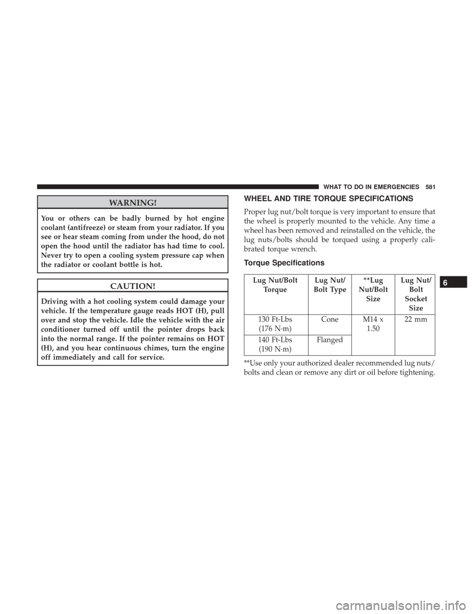
WHEEL AND TIRE TORQUE SPECIFICATIONS
Proper lug nut/bolt torque is very important to ensure that
the wheel is properly mounted to the vehicle. Any time a
wheel has been removed and reinstalled on the vehicle, the
lug nuts/bolts should be torqued using a properly cali-
brated torque wrench.
Torque Specifications
Lug Nut/BoltTorque Lug Nut/
Bolt Type **Lug
Nut/Bolt Size Lug Nut/
Bolt
Socket Size
130 Ft-Lbs (176 N·m) Cone M14 x
1.5022 mm
140 Ft-Lbs (190 N·m) Flanged
**Use only your authorized dealer recommended lug nuts/
bolts and clean or remove any dirt or oil before tightening.6
WHAT TO DO IN EMERGENCIES 581
Page 619 of 734

Hub Caps/Wheel Covers — If Equipped
The hub caps must be removed before raising the vehicle
off the ground.
CAUTION!
Use extreme caution when removing the front and rear
center caps. Damage can occur to the center cap and/or
the wheel if screwdriver type tools are used. A pulling
motion, not a pry off motion, is recommended to
remove the caps.
For single rear wheel (SRW) models, use the flat blade on
the end of the lug wrench to pull the hub cap off. Insert the
blade end into the pull off notch and carefully pull the hub
cap off with a back and forth motion.
On 3500 models with dual rear wheels (DRW), you must
first remove the hub caps. The jack handle driver has a
hook at one end that will fit in the pull off notch of the rear
hub caps. Position the hook and pull straight out on the
ratchet firmly. The hub cap should pop off. The wheel skins
can now be removed. For the front hub cap, use the flat
blade on the end of the lug wrench to pull the caps off. The
wheel skin can now be removed.
CAUTION!
• Use a pulling motion to remove the hub cap. Do not
use a twisting motion when removing the hub cap,
damage to the hub cap; finish may occur.
• The rear hub caps on the dual rear wheel has two
pull off notches. Make sure that the hook of the jack
handle driver is located squarely in the cap notch
before attempting to pull off.
You must use the flat end of the lug wrench to pull off the
wheel skins. Locate the hub cap pull notches (2 notches on
each cap). Insert the flat tip completely and using a back
and forth motion, loosen the wheel skin. Repeat this
procedure around the tire until the skin pops off.
Replace the wheel skins first using a rubber mallet. When
replacing the hub caps, tilt the cap retainer over the lug nut
bolt circle and strike the high side down with a rubber
mallet. Be sure that the hub caps and wheel skins are firmly
seated around the wheel.
6
WHAT TO DO IN EMERGENCIES 617
Page 718 of 734

Adding Engine Coolant (Antifreeze).............663
Adding Fuel ............................. .548
Additives, Fuel ........................... .544
Adjust Down .................................119
Forward ............................119,120
Rearward ...........................119,120
Up ...................................119
Adjustable Pedals ......................... .152
Air Bag Air Bag Operation .........................60
Enhanced Accident Response ..............66, 630
Event Data Recorder (EDR) .................630
If A Deployment Occurs ....................65
Knee Impact Bolsters .......................60
Maintaining Your Air Bag System ..............67
Side Air Bags ............................61
Air Bag Light .......................... .96, 241
Air Bag Maintenance .........................67
Air Cleaner, Engine (Engine Air Cleaner Filter) ......643
Air Conditioner Maintenance ..................649
Air Conditioning .......................... .330
Air Conditioning Controls ....................330
Air Conditioning Filter ...................347, 650
Air Conditioning, Operating Tips ............346, 348Air Conditioning Refrigerant
...............649, 650
Air Conditioning System ...............330, 345, 649
Air Pressure, Tires ......................... .519
Air Suspension ........................ .438, 444
Alarm, Panic ...............................24
Alarm (Security Alarm) ....................19, 244
Alarm System (Security Alarm) .................19
Alterations/Modifications, Vehicle ................7
Antifreeze (Engine Coolant) ................662, 697
Disposal .............................. .664
Anti-Lock Brake System (ABS) .................495
Appearance Care .......................... .672
Ashtray ................................ .189
Assist, Hill Start .......................... .498
Auto Down Power Windows ...................40
Automatic Door Locks ........................
34
Automatic Headlights ...................... .139
Automatic High Beams ..................... .141
Automatic Temperature Control (ATC) ...........345
Automatic Transmission ..................388, 672
Adding Fluid ....................... .671, 672
Fluid And Filter Changes ...................672
Fluid Change .......................... .672
Fluid Level Check .................669, 670, 671
Fluid Type ......................... .669, 701
716 INDEX