Battery Ram 2500 2017 Workshop Manual
[x] Cancel search | Manufacturer: RAM, Model Year: 2017, Model line: 2500, Model: Ram 2500 2017Pages: 734, PDF Size: 7.3 MB
Page 635 of 734
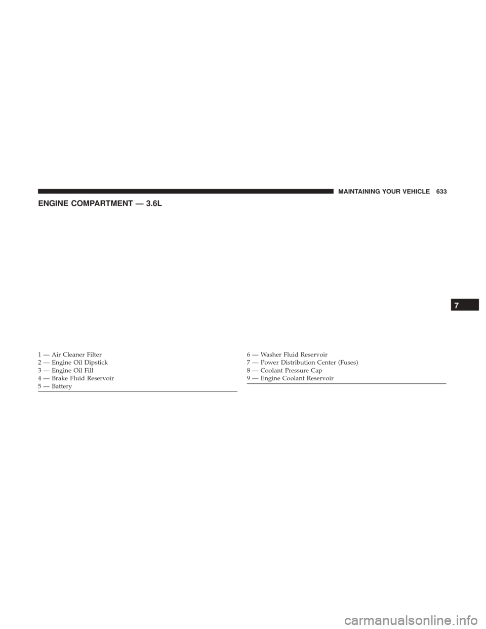
ENGINE COMPARTMENT — 3.6L
1 — Air Cleaner Filter
2 — Engine Oil Dipstick
3 — Engine Oil Fill
4 — Brake Fluid Reservoir
5 — Battery6 — Washer Fluid Reservoir
7 — Power Distribution Center (Fuses)
8 — Coolant Pressure Cap
9 — Engine Coolant Reservoir
7
MAINTAINING YOUR VEHICLE 633
Page 636 of 734
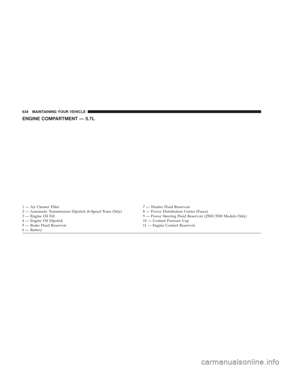
ENGINE COMPARTMENT — 5.7L
1 — Air Cleaner Filter7 — Washer Fluid Reservoir
2 — Automatic Transmission Dipstick (6-Speed Trans Only) 8 — Power Distribution Center (Fuses)
3 — Engine Oil Fill 9 — Power Steering Fluid Reservoir (2500/3500 Models Only)
4 — Engine Oil Dipstick 10 — Coolant Pressure Cap
5 — Brake Fluid Reservoir 11 — Engine Coolant Reservoir
6 — Battery 634 MAINTAINING YOUR VEHICLE
Page 637 of 734
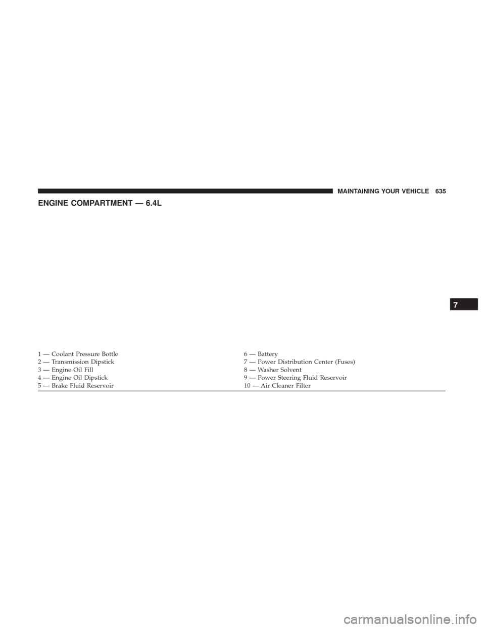
ENGINE COMPARTMENT — 6.4L
1 — Coolant Pressure Bottle6 — Battery
2 — Transmission Dipstick 7 — Power Distribution Center (Fuses)
3 — Engine Oil Fill 8 — Washer Solvent
4 — Engine Oil Dipstick 9 — Power Steering Fluid Reservoir
5 — Brake Fluid Reservoir 10 — Air Cleaner Filter
7
MAINTAINING YOUR VEHICLE 635
Page 639 of 734
WARNING!(Continued)
vehicle control could occur that may result in an
accident involving serious injury or death.
• Access, or allow others to access, information
stored in your vehicle systems, including personal
information.
For further information, refer to “Privacy Practices — If
Equipped With Uconnect 8.4 Radio” and “Uconnect Cy-
berSecurity” in “All About Uconnect Access” in your
Owner ’s Manual Radio Supplement and “Cybersecurity”
in “Understanding Your Instrument Panel”.
Loose Fuel Filler Cap Message
If the vehicle diagnostic system determines that
the fuel filler cap is loose, improperly installed,
or damaged, a loose gascap indicator will dis-
play in the instrument cluster telltale display
area. Refer to “Instrument Cluster Display” in “Under-
standing Your Instrument Panel” for further information.
Tighten the fuel filler cap properly and push the SELECT
button to turn off the message. If the problem continues,
the message will appear the next time the vehicle is started. A loose, improperly installed, or damaged fuel filler cap
may also turn on the Malfunction Indicator Light (MIL).
EMISSIONS INSPECTION AND MAINTENANCE
PROGRAMS
In some localities, it may be a legal requirement to pass an
inspection of your vehicle’s emissions control system.
Failure to pass could prevent vehicle registration.
For states that require an Inspection and Mainte-
nance (I/M), this check verifies the “Malfunction
Indicator Light (MIL)” is functioning and is not on
when the engine is running, and that the OBD II system is
ready for testing.
Normally, the OBD II system will be ready. The OBD II
system may notbe ready if your vehicle was recently
serviced, or recently had a dead battery or a battery
replacement. If the OBD II system should be determined
not ready for the I/M test, your vehicle may fail the test.
7
MAINTAINING YOUR VEHICLE 637
Page 640 of 734
Your vehicle has a simple ignition actuated test, which you
can use prior to going to the test station. To check if your
vehicle’s OBD II system isready, you must do the follow-
ing:
1. Cycle the ignition to the ON mode, but do not crank or start the engine.
NOTE: If you crank or start the engine, you will have to
start this test over.
2. As soon as you cycle the ignition to the ON mode, you will see the “Malfunction Indicator Light (MIL)” symbol
come on as part of a normal bulb check.
3. Approximately 15 seconds later, one of two things will happen:
• The MIL will flash for about 10 seconds and then return
to being fully illuminated until you cycle the ignition
OFF or start the engine. This means that your vehicle’s
OBD II system is not readyand you should notproceed
to the I/M station. •
The MIL will not flash at all and will remain fully
illuminated until you place the ignition in the off posi-
tion or start the engine. This means that your vehicle’s
OBD II system is readyand you can proceed to the I/M
station.
If your OBD II system is not ready,you should see your
authorized dealer or repair facility. If your vehicle was
recently serviced or had a battery failure or replacement,
you may need to do nothing more than drive your vehicle
as you normally would in order for your OBD II system to
update. A recheck with the above test routine may then
indicate that the system is now ready.
Regardless of whether your vehicle’s OBD II system is
ready or not, if the MIL is illuminated during normal
vehicle operation you should have your vehicle serviced
before going to the I/M station. The I/M station can fail
your vehicle because the MIL is on with the engine
running.
638 MAINTAINING YOUR VEHICLE
Page 650 of 734
Maintenance-Free Battery
Your vehicle is equipped with a maintenance-free battery.
You will never have to add water, nor is periodic mainte-
nance required.
WARNING!
•Battery fluid is a corrosive acid solution and can
burn or even blind you. Do not allow battery fluid to
contact your eyes, skin, or clothing. Do not lean over
a battery when attaching clamps. If acid splashes in
eyes or on skin, flush the area immediately with
large amounts of water. Refer to “Jump-Starting
Procedures” in “What To Do In Emergencies” for
further information.
• Battery gas is flammable and explosive. Keep flame
or sparks away from the battery. Do not use a booster
battery or any other booster source with an output
greater than 12 Volts. Do not allow cable clamps to
touch each other.
• Battery posts, terminals, and related accessories con-
tain lead and lead compounds. Wash hands after
handling.
CAUTION!
• It is essential when replacing the cables on the
battery that the positive cable is attached to the
positive post and the negative cable is attached to the
negative post. Battery posts are marked positive (+)
and negative (-) and are identified on the battery
case. Cable clamps should be tight on the terminal
posts and free of corrosion.
• If a “fast charger” is used while the battery is in the
vehicle, disconnect both vehicle battery cables before
connecting the charger to the battery. Do not use a
“fast charger” to provide starting voltage.
648 MAINTAINING YOUR VEHICLE
Page 682 of 734
Power Distribution Center
The Power Distribution Center is located in the engine
compartment near the battery. This center contains car-
tridge fuses, micro fuses, relays, and circuit breakers. A
description of each fuse and component may be stamped
on the inside cover, otherwise the cavity number of each
fuse is stamped on the inside cover that corresponds to the
following chart.
Power Distribution Center Location
680 MAINTAINING YOUR VEHICLE
Page 686 of 734
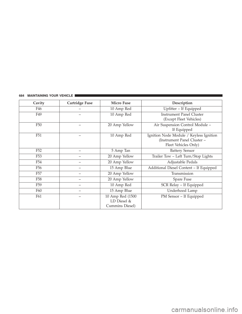
CavityCartridge Fuse Micro Fuse Description
F46 –10 Amp Red Upfitter – If Equipped
F49 –10 Amp Red Instrument Panel Cluster
(Except Fleet Vehicles)
F50 –20 Amp Yellow Air Suspension Control Module –
If Equipped
F51 –10 Amp Red Ignition Node Module / Keyless Ignition
(Instrument Panel Cluster –Fleet Vehicles Only)
F52 –5 Amp Tan Battery Sensor
F53 –20 Amp Yellow Trailer Tow – Left Turn/Stop Lights
F54 –20 Amp Yellow Adjustable Pedals
F56 –15 Amp Blue Additional Diesel Content – If Equipped
F57 –20 Amp Yellow Transmission
F58 –20 Amp Yellow Spare Fuse
F59 –10 Amp Red SCR Relay – If Equipped
F60 –15 Amp Blue Underhood Lamp
F61 –10 Amp Red (1500
LD Diesel &
Cummins Diesel) PM Sensor – If Equipped
684 MAINTAINING YOUR VEHICLE
Page 690 of 734
CAUTION!
•When installing the power distribution center cover,
it is important to ensure the cover is properly posi-
tioned and fully latched. Failure to do so may allow
water to get into the power distribution center and
possibly result in an electrical system failure.
• When replacing a blown fuse, it is important to use
only a fuse having the correct amperage rating. The
use of a fuse with a rating other than indicated may
result in a dangerous electrical system overload. If a
properly rated fuse continues to blow, it indicates a
problem in the circuit that must be corrected.
VEHICLE STORAGE
If you are storing your vehicle for more than 21 days, we
recommend that you take the following steps to minimize
the drain on your vehicle’s battery:
• Disconnect the negative cable from battery.
• Any time you store your vehicle or keep it out of service
(i.e., vacation) for two weeks or more, run the air
conditioning system at idle for about five minutes in the
fresh air and high blower setting. This will ensure
adequate system lubrication to minimize the possibility
of compressor damage when the system is started again.
REPLACEMENT BULBS
All of the inside bulbs are brass or glass-wedge base.
Aluminum base bulbs are not approved.
Interior Bulbs
Bulb Number
Overhead Console Lamps TS 212–9
Dome Lamp 7679
For lighted switches, see your authorized dealer for
replacement instructions.
688 MAINTAINING YOUR VEHICLE
Page 692 of 734
BULB REPLACEMENT
NOTE:Lens fogging can occur under certain atmospheric
conditions. This will usually clear as atmospheric condi-
tions change to allow the condensation to change back into
a vapor. Turning the lamps on will usually accelerate the
clearing process.
Base Quad / Premium Bi-Halogen: Low Beam
Headlamp, High Beam Headlamp, Front Park And
Turn — If Equipped
1. Open the hood.
2. Disconnect and isolate the negative battery cable.
3. Remove the six plastic push-in fasteners that secure the upper radiator seal to the grille support and both fender
ledges.
4. Remove the two plastic push-in rivets that secure the upper radiator seal to the radiator.
5. Remove the upper radiator seal from the vehicle. 6. Remove the two headlamp assembly attachment screws.
7. Reach into the front wheel house ahead of the front
wheel, remove the fastener, and lift the cover over the
access hole in the front of the wheel house splash shield.
Access to the rear of the lamp can be gained through this
access hole.
Headlamp Assembly Attachment Screw Locations
690 MAINTAINING YOUR VEHICLE