Instrument panel Ram 2500 2018 Owner's Manual
[x] Cancel search | Manufacturer: RAM, Model Year: 2018, Model line: 2500, Model: Ram 2500 2018Pages: 700, PDF Size: 8.86 MB
Page 416 of 700

NOTE:
•When the fuel nozzle “clicks” or shuts off, the fuel tank
is full.
• Tighten the gas cap until you hear a “clicking” sound.
This is an indication that the gas cap is tightened
properly. The MIL in the instrument cluster may turn on
if the gas cap is not secured properly. Make sure that the
gas cap is tightened each time the vehicle is refueled.
WARNING!
Static electricity can cause an ignition of flammable
liquid, vapor or gas in any vehicle or trailer. To reduce
risk of serious injury or death when filling containers:
•Always place container on the ground before filling.
• Keep the pump nozzle in contact with the container
when you are filling it.
• Use only approved containers for flammable liquid.
• Do not leave container unattended while filling.
• A static electric charge could cause a spark and fire
hazard.
Loose Fuel Filler Cap Message
If the vehicle diagnostic system determines that
the fuel filler cap is loose, improperly installed,
or damaged, a loose gascap indicator will dis-
play in the instrument cluster telltale display
area. Refer to “Instrument Cluster Display” in “Getting To
Know Your Instrument Panel” for further information.
Tighten the fuel filler cap properly and push the RIGHT
button to turn off the message. If the problem continues,
the message will appear the next time the vehicle is started.
VEHICLE LOADING
Gross Vehicle Weight Rating (GVWR)
The GVWR is the total permissible weight of your vehicle
including driver, passengers, vehicle, options and cargo.
The label also specifies maximum capacities of front and
rear axle systems (GAWR). Total load must be limited so
GVWR and front and rear GAWR are not exceeded.
Payload
The payload of a vehicle is defined as the allowable load
weight a truck can carry, including the weight of the driver,
all passengers, options and cargo.
414 STARTING AND OPERATING
Page 431 of 700

Repeat steps 8 and 9 until the GAIN setting is at a point just
below trailer wheel lockup. If towing a heavier trailer,trailer wheel lockup may not be attainable even with the
maximum GAIN setting of 10.
Light Electric Heavy Electric Light EOH
Heavy EOH
Type of Trailer Brakes Electric Trailer Brakes Electric Trailer Brakes Electric over Hydrau- lic Trailer BrakesElectric over Hydrau-
lic Trailer Brakes
Load *Under 10,000 lbs *Above 10,000 lbs *Under 10,000 lbs *Above 10,000 lbs
* The suggested selection depends and may change de-
pending on the customer preferences for braking perfor-
mance. Condition of the trailer brakes, driving and road
state may also affect the selection.
Display Messages
The trailer brake control interacts with the instrument
cluster display. Display messages, along with a single
chime, will be displayed when a malfunction is determined
in the trailer connection, trailer brake control, or on the
trailer. Refer to “Instrument Cluster Display” in “Getting
To Know Your Instrument Panel” for further information.
CAUTION!
Connecting a trailer that is not compatible with the
ITBM system may result in reduced or complete loss of
trailer braking. There may be a increase in stopping
distance or trailer instability which could result in
damage to your vehicle, trailer, or other property.
WARNING!
Connecting a trailer that is not compatible with the
ITBM system may result in reduced or complete loss of
trailer braking. There may be a increase in stopping
distance or trailer instability which could result in
personal injury.
6
STARTING AND OPERATING 429
Page 453 of 700

•An In-Vehicle Audio message will state “Vehicle device
requires service. Please contact your dealer.”
WARNING!
•Ignoring the Rearview Mirror light could mean you
will not have SOS Call services. If the Rearview
Mirror light is illuminated, have an authorized
dealer service the SOS Call system immediately.
• The Occupant Restraint Control module turns on the
air bag Warning Light on the instrument panel if a
malfunction in any part of the system is detected. If
the Air Bag Warning Light is illuminated, have an
authorized dealer service the Occupant Restraint
Control system immediately.
Even if the SOS Call system is fully functional, factors
beyond FCA US LLC’s control may prevent or stop the SOS
Call system operation. These include, but are not limited
to, the following factors:
• Delayed accessories mode is active.
• The ignition is in the OFF position.
• The vehicle’s electrical systems are not intact. •
The SOS Call system software and/or hardware are
damaged during a crash.
• The vehicle battery loses power or becomes discon-
nected during a vehicle crash.
• LTE (voice/data) or 4G (data) network and/or Global
Positioning Satellite signals are unavailable or ob-
structed.
• Equipment malfunction at the SOS operator facility.
• Operator error by the SOS operator.
• LTE (voice/data) or 4G (data) network congestion.
• Weather.
• Buildings, structures, geographic terrain, or tunnels.
WARNING!
ALWAYS obey traffic laws and pay attention to the
road. ALWAYS drive safely with your hands on the
steering wheel. You have full responsibility and as-
sume all risks related to the use of the Uconnect and
SiriusXM Guardian features and applications in this
vehicle. Only use Uconnect features and SiriusXM
(Continued)
7
IN CASE OF EMERGENCY 451
Page 466 of 700
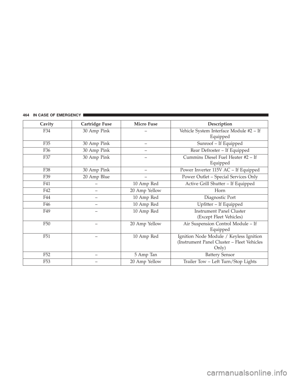
CavityCartridge Fuse Micro Fuse Description
F34 30 Amp Pink –Vehicle System Interface Module #2 – If
Equipped
F35 30 Amp Pink –Sunroof – If Equipped
F36 30 Amp Pink –Rear Defroster – If Equipped
F37 30 Amp Pink –Cummins Diesel Fuel Heater #2 – If
Equipped
F38 30 Amp Pink –Power Inverter 115V AC – If Equipped
F39 20 Amp Blue –Power Outlet – Special Services Only
F41 –10 Amp Red Active Grill Shutter – If Equipped
F42 –20 Amp Yellow Horn
F44 –10 Amp Red Diagnostic Port
F46 –10 Amp Red Upfitter – If Equipped
F49 –10 Amp Red Instrument Panel Cluster
(Except Fleet Vehicles)
F50 –20 Amp Yellow Air Suspension Control Module – If
Equipped
F51 –10 Amp Red Ignition Node Module / Keyless Ignition
(Instrument Panel Cluster – Fleet VehiclesOnly)
F52 –5 Amp Tan Battery Sensor
F53 –20 Amp Yellow Trailer Tow – Left Turn/Stop Lights
464 IN CASE OF EMERGENCY
Page 469 of 700
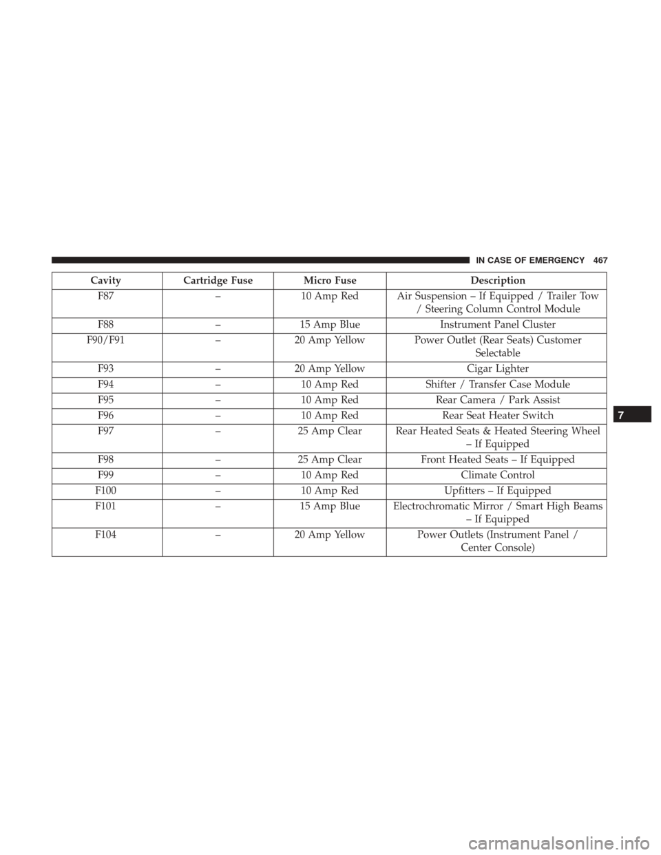
CavityCartridge Fuse Micro Fuse Description
F87 –10 Amp Red Air Suspension – If Equipped / Trailer Tow
/ Steering Column Control Module
F88 –15 Amp Blue Instrument Panel Cluster
F90/F91 –20 Amp Yellow Power Outlet (Rear Seats) Customer
Selectable
F93 –20 Amp Yellow Cigar Lighter
F94 –10 Amp Red Shifter / Transfer Case Module
F95 –10 Amp Red Rear Camera / Park Assist
F96 –10 Amp Red Rear Seat Heater Switch
F97 –25 Amp Clear Rear Heated Seats & Heated Steering Wheel
– If Equipped
F98 –25 Amp Clear Front Heated Seats – If Equipped
F99 –10 Amp Red Climate Control
F100 –10 Amp Red Upfitters – If Equipped
F101 –15 Amp Blue Electrochromatic Mirror / Smart High Beams
– If Equipped
F104 –20 Amp Yellow Power Outlets (Instrument Panel /
Center Console)
7
IN CASE OF EMERGENCY 467
Page 471 of 700

If your vehicle is not equipped with a touchscreen, this
feature can be activated through the instrument cluster
display. Refer to “Instrument Cluster Display” in “Getting
To Know Your Instrument Panel” for further information.
Jack Location
The jack and jack tools are stored under the front passenger
seat.
Removal Of Jack And Tools (1500 Series)
To access the jack and jack tools, you must remove the
plastic access cover located on the side of the front passen-
ger ’s seat. To remove the cover, pull the front part of the
cover (closest to the front of the seat) toward you to release
a locking tab. Once the front of the cover is loose, slide the
cover toward the front of the seat until it is free from the
seat frame.
Jack Access Cover
7
IN CASE OF EMERGENCY 469
Page 519 of 700
SCHEDULED SERVICING
Your vehicle is equipped with an automatic oil change
indicator system. The oil change indicator system will
remind you that it is time to take your vehicle in for
scheduled maintenance.
Based on engine operation conditions, the oil change
indicator message will illuminate. This means that service
is required for your vehicle. Operating conditions such as
frequent short-trips, trailer tow, extremely hot or cold
ambient temperatures, and E85 fuel usage will influence
when the “Oil Change Required” message is displayed.
Severe Operating Conditions can cause the change oil
message to illuminate as early as 3,500 miles (5,600 km)
since last reset. Have your vehicle serviced as soon as
possible, within the next 500 miles (805 km).
Your authorized dealer will reset the oil change indicator
message after completing the scheduled oil change. If a
scheduled oil change is performed by someone other than
your authorized dealer, the message can be reset by
referring to the steps described under “Instrument Cluster
Display” in “Getting To Know Your Instrument Panel”.1500 Models Only
NOTE:
Under no circumstances should oil change
intervals exceed 10,000 miles (16,000 km), twelve months
or 350 hours of engine run time, whichever comes first. The
350 hours of engine run or idle time is generally only a
concern for fleet customers.
2500 – 3500 Models Only
NOTE: Under no circumstances should oil change
intervals exceed 8,000 miles (13,000 km), twelve months or
350 hours of engine run time, whichever comes first. The
350 hours of engine run or idle time is generally only a
concern for fleet customers.
8
SERVICING AND MAINTENANCE 517
Page 595 of 700

IDENTIFICATION DATA
Vehicle Identification Number
The Vehicle Identification Number (VIN) is found on the
left front corner of the instrument panel, visible through
the windshield. This number also appears on the vehicle
frame and underbody as well as the Automobile Informa-
tion Disclosure Label affixed to a window on your vehicle,
the vehicle registration and title.
NOTE:It is illegal to remove or alter the VIN.
BRAKE SYSTEM
If power assist is lost for any reason (for example, repeated
brake applications with the engine off), the brakes will still
function. However, you will experience a substantial in-
crease in braking effort to stop the vehicle.
If either the front or rear hydraulic system loses normal
braking capability, the remaining system will still function
with some loss of overall braking effectiveness. This will be
evident by increased pedal travel during application,
greater pedal force required to slow or stop, and activation
of the “Brake Warning Light” and the “ABS Warning
Light” (if equipped) during brake use.
Hydraulic Brake Assist — 2500/3500 Models Only
(Except Power Wagon)
The brake system power assist is provided by a hydro-
boost unit which shares fluid with the power steering
system. You may experience some clicking or hissing
noises from the hydro-boost system during hard braking
conditions.
NOTE:Under cold temperatures, pedal effort will be
higher than normal until the power steering fluid reaches
operating temperature.
Vehicle Identification Number
9
TECHNICAL SPECIFICATIONS 593
Page 615 of 700
NOTE:
•FCA US LLC or your dealer may contact you directly
regarding software updates.
• To help further improve vehicle security and minimize
the potential risk of a security breach, vehicle owners
should:
• Routinely check www.driveuconnect.com/software-
update to learn about available Uconnect software
updates.
• Only connect and use trusted media devices (e.g.
personal mobile phones, USBs, CDs).
Privacy of any wireless and wired communications cannot
be assured. Third parties may unlawfully intercept infor-
mation and private communications without your consent.
For further information, refer to “Data Collection & Pri-
vacy” in “Uconnect + SiriusXM Guardian” in your
Uconnect Owner’s Manual Supplement and “Onboard
Diagnostic System (OBD II) Cybersecurity” in “Getting To
Know Your Instrument Panel”.UCONNECT SETTINGS
The Uconnect system uses a combination of buttons on the
touchscreen and buttons on the faceplate located on the
center of the instrument panel that allows you to access
and change the customer programmable features. Many
features can vary by vehicle.
Uconnect 3.0 Power Hard Button
10
MULTIMEDIA 613
Page 630 of 700
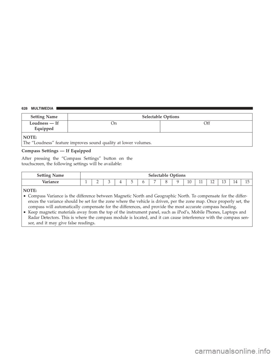
Setting NameSelectable Options
Loudness — If Equipped On
Off
NOTE:
The “Loudness” feature improves sound quality at lower volumes.
Compass Settings — If Equipped
After pressing the “Compass Settings” button on the
touchscreen, the following settings will be available:
Setting Name Selectable Options
Variance 123456789101112131415
NOTE:
•Compass Variance is the difference between Magnetic North and Geographic North. To compensate for the differ-
ences the variance should be set for the zone where the vehicle is driven, per the zone map. Once properly set, the
compass will automatically compensate for the differences, and provide the most accurate compass heading.
•Keep magnetic materials away from the top of the instrument panel, such as iPod’s, Mobile Phones, Laptops and
Radar Detectors. This is where the compass module is located, and it can cause interference with the compass sen-
sor, and it may give false readings.
628 MULTIMEDIA