maintenance Ram 2500 2018 Owner's Manual
[x] Cancel search | Manufacturer: RAM, Model Year: 2018, Model line: 2500, Model: Ram 2500 2018Pages: 372, PDF Size: 7.1 MB
Page 91 of 372

CAUTION!
• The TPMS has been optimized for theoriginal equipment tires and wheels.
TPMS pressures and warning have been
established for the tire size equipped on
your vehicle. Undesirable system opera-
tion or sensor damage may result when
using replacement equipment that is not
of the same size, type, and/or style.
Aftermarket wheels can cause sensor
damage.
• Using aftermarket tire sealants may
cause the Tire Pressure Monitoring Sys-
tem (TPMS) sensor to become inoper-
able. After using an aftermarket tire
sealant it is recommended that you take
your vehicle to an authorized dealership
to have your sensor function checked.
• After inspecting or adjusting the tire
pressure always reinstall the valve stem
cap. This will prevent moisture and dirt
from entering the valve stem, which
could damage the TPMS sensor. NOTE:
• The TPMS is not intended to replace nor-
mal tire care and maintenance or to provide
warning of a tire failure or condition.
• The TPMS should not be used as a tire pressure gauge while adjusting your tire
pressure.
• Driving on a significantly under-inflated tire causes the tire to overheat and can lead to
tire failure. Under-inflation also reduces
fuel efficiency and tire tread life, and may
affect the vehicle’s handling and stopping
ability.
• The TPMS is not a substitute for proper tire maintenance, and it is the driver’s respon-
sibility to maintain correct tire pressure
using an accurate tire pressure gauge, even
if under-inflation has not reached the level
to trigger illumination of the TPM Telltale
Light.
• Seasonal temperature changes will affect tire pressure, and the TPMS will monitor
the actual tire pressure in the tire.
Premium System
The Tire Pressure Monitor System (TPMS)
uses wireless technology with wheel rim
mounted electronic sensors to monitor tire
pressure levels. Sensors, mounted to each
wheel as part of the valve stem, transmit tire
pressure readings to the receiver module.
NOTE:
It is particularly important for you to check
the tire pressure in all of the tires on your
vehicle monthly and to maintain the proper
pressure.
The TPMS consists of the following compo-
nents:
• Receiver module
• Four tire pressure monitoring sensors
• Various tire pressure monitoring systemmessages, which display in the instrument
cluster
• Tire pressure monitoring telltale light
89
Page 106 of 372
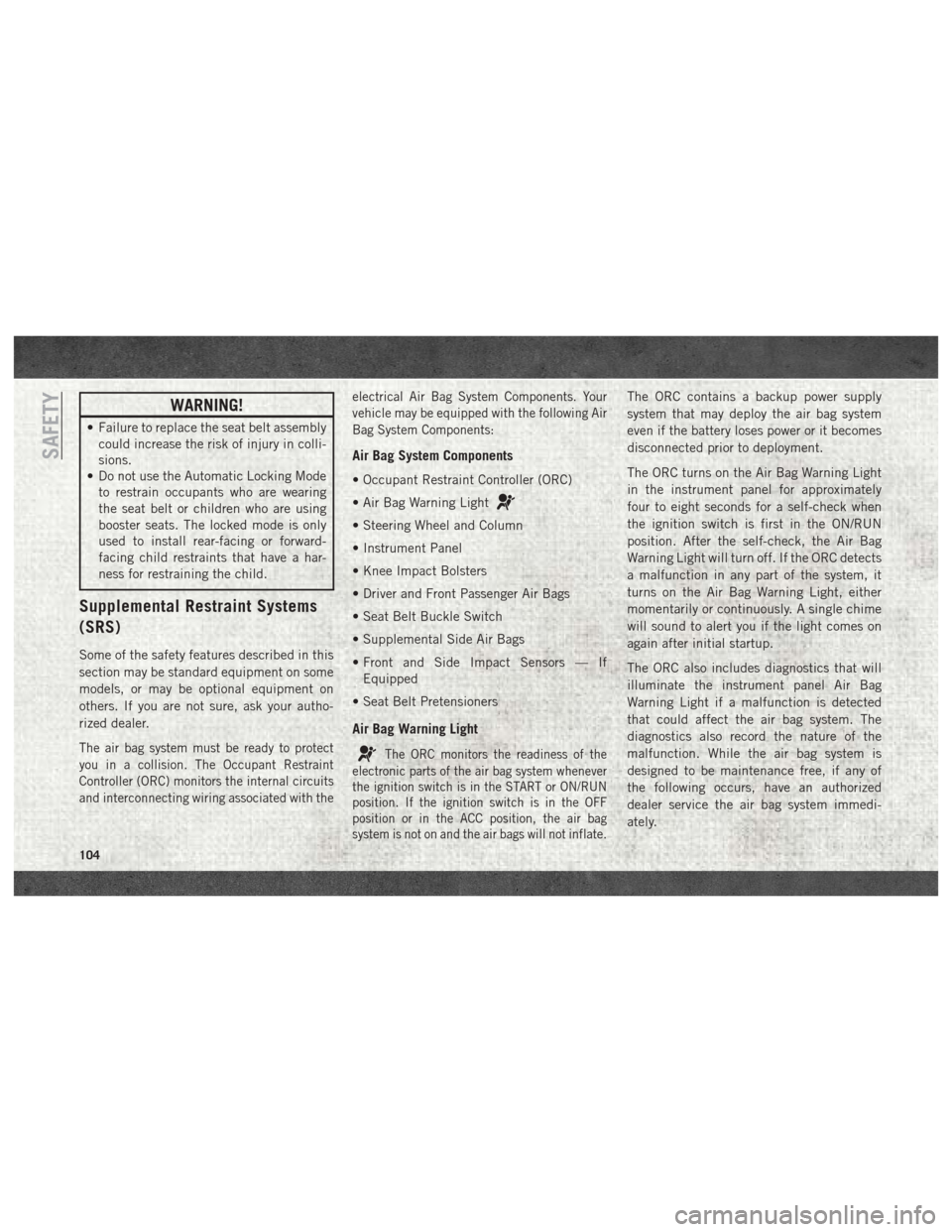
WARNING!
• Failure to replace the seat belt assemblycould increase the risk of injury in colli-
sions.
• Do not use the Automatic Locking Mode
to restrain occupants who are wearing
the seat belt or children who are using
booster seats. The locked mode is only
used to install rear-facing or forward-
facing child restraints that have a har-
ness for restraining the child.
Supplemental Restraint Systems
(SRS)
Some of the safety features described in this
section may be standard equipment on some
models, or may be optional equipment on
others. If you are not sure, ask your autho-
rized dealer.
The air bag system must be ready to protect
you in a collision. The Occupant Restraint
Controller (ORC) monitors the internal circuits
and interconnecting wiring associated with the electrical Air Bag System Components. Your
vehicle may be equipped with the following Air
Bag System Components:
Air Bag System Components
• Occupant Restraint Controller (ORC)
• Air Bag Warning Light
• Steering Wheel and Column
• Instrument Panel
• Knee Impact Bolsters
• Driver and Front Passenger Air Bags
• Seat Belt Buckle Switch
• Supplemental Side Air Bags
• Front and Side Impact Sensors — If
Equipped
• Seat Belt Pretensioners
Air Bag Warning Light
The ORC monitors the readiness of the
electronic parts of the air bag system whenever
the ignition switch is in the START or ON/RUN
position. If the ignition switch is in the OFF
position or in the ACC position, the air bag
system is not on and the air bags will not inflate.
The ORC contains a backup power supply
system that may deploy the air bag system
even if the battery loses power or it becomes
disconnected prior to deployment.
The ORC turns on the Air Bag Warning Light
in the instrument panel for approximately
four to eight seconds for a self-check when
the ignition switch is first in the ON/RUN
position. After the self-check, the Air Bag
Warning Light will turn off. If the ORC detects
a malfunction in any part of the system, it
turns on the Air Bag Warning Light, either
momentarily or continuously. A single chime
will sound to alert you if the light comes on
again after initial startup.
The ORC also includes diagnostics that will
illuminate the instrument panel Air Bag
Warning Light if a malfunction is detected
that could affect the air bag system. The
diagnostics also record the nature of the
malfunction. While the air bag system is
designed to be maintenance free, if any of
the following occurs, have an authorized
dealer service the air bag system immedi-
ately.
SAFETY
104
Page 144 of 372

STARTING THE ENGINE — 3.0L
DIESEL ENGINE
Before starting your vehicle, adjust your seat,
both inside and outside mirrors, and fasten
your seat belts.
The starter is allowed to crank for up to
30-second intervals. Waiting a few minutes
between such intervals will protect the starter
from overheating.
WARNING!
• Before exiting a vehicle, always come toa complete stop, then shift the auto-
matic transmission into PARK and apply
the parking brake. Always make sure the
keyless ignition node is in the OFF
mode, remove the key fob from the ve-
hicle and lock the vehicle.
• Never leave children alone in a vehicle,
or with access to an unlocked vehicle.
Leaving children in a vehicle unattended
is dangerous for a number of reasons. A
child or others could be seriously or
fatally injured. Children should be
WARNING!
warned not to touch the parking brake,
brake pedal or the gear selector.
• Do not leave the key fob in or near the
vehicle, or in a location accessible to
children, and do not leave the ignition of
a vehicle equipped with Keyless Enter-
N-Go in the ACC or ON/RUN mode. A
child could operate power windows,
other controls, or move the vehicle.
• Do not leave children or animals inside
parked vehicles in hot weather. Interior
heat build-up may cause serious injury
or death.
NOTE:
Engine start up in very low ambient tempera-
ture could result in evident white smoke. This
condition will disappear as the engine warms
up.
CAUTION!
• The engine is allowed to crank as long as 30 seconds. If the engine fails to start
during this period, please wait at least
CAUTION!
two minutes for the starter to cool before
repeating start procedure.
• If the “Water in Fuel Indicator Light”
remains on, DO NOT START engine be-
fore you drain the water from the fuel
filters to avoid engine damage. Refer to
“Draining Fuel/Water Separator Filter”
in “Servicing And Maintenance” in your
Diesel Supplement on www.mopar.com/
en-us/care/owners-manual.html (U.S.
Residents) or www.owners.mopar.ca
(Canadian Residents) for further infor-
mation.
Normal Starting Using ENGINE
STOP/START Button
Observe the instrument panel cluster lights
when starting the engine.
NOTE:
Normal starting of either a cold or a warm
engine is obtained without pumping or press-
ing the accelerator pedal.
STARTING AND OPERATING
142
Page 145 of 372

To Turn On The Engine Using The ENGINE START/
STOP Button
1. The transmission must be in PARK.
2. Press and hold the brake pedal whilepushing the ENGINE START/STOP button
once.
NOTE:
A delay of the start of up to five seconds is
possible under very cold conditions. The
"Wait to Start" telltale will be illuminated
during the pre-heat process, When the
engine Wait To Start light goes off the
engine will automatically crank.
CAUTION!
If the “Water in Fuel Indicator Light” re-
mains on, DO NOT START engine before
you drain the water from the fuel filters to
avoid engine damage. Refer to “Draining
Fuel/Water Separator Filter” in “Servicing
And Maintenance” in your Diesel Supple-
ment at www.mopar.com/en-us/care/
owners-manual.html (U.S. Residents) or
www.owners.mopar.ca (Canadian Resi-
dents) for further information. 3. The system takes over and attempts to
start the vehicle. If the vehicle fails to
start, the starter will disengage automati-
cally after 25 seconds.
4. If you wish to stop the cranking of the engine prior to the engine starting, push
the button again.
NOTE:
Normal starting of either a cold or a warm
engine is obtained without pumping or press-
ing the accelerator pedal.
To Turn Off The Engine Using ENGINE START/
STOP Button
1. Place the gear selector in PARK, then push and release the ENGINE START/
STOP button.
2. The ignition will return to the OFF mode.
3. If the gear selector is not in PARK, the ENGINE START/STOP button must be
held for two seconds or three short pushes
in a row with the vehicle speed above
5 MPH (8 km/h) before the engine will shut off. The ignition will remain in the
ACC mode until the gear selector is in
PARK and the button is pushed twice to
the OFF mode.
4. If the gear selector is not in PARK and the ENGINE START/STOP button is pushed
once with the vehicle speed above 5 MPH
(8 km/h), the instrument cluster will dis-
play a “Vehicle Not In Park” message and
the engine will remain running. Never
leave a vehicle out of the PARK position,
or it could roll.
NOTE:
If the gear selector is not in PARK, and the
ENGINE START/STOP button is pushed once
with the vehicle speed below 5 MPH (8 km/
h), the engine will shut off and the ignition
will remain in the ACC position. If vehicle
speed drops below 1.2 MPH (1.9 km/h), the
vehicle may AutoPark. See AutoPark section
for further details.
143
Page 193 of 372
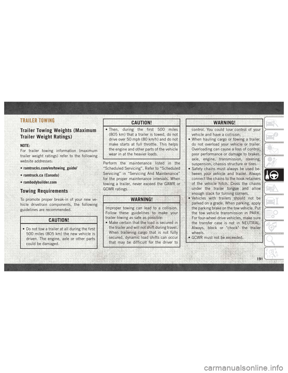
TRAILER TOWING
Trailer Towing Weights (Maximum
Trailer Weight Ratings)
NOTE:
For trailer towing information (maximum
trailer weight ratings) refer to the following
website addresses:
•ramtrucks.com/en/towing_guide/
• ramtruck.ca (Canada)
• rambodybuilder.com
Towing Requirements
To promote proper break-in of your new ve-
hicle drivetrain components, the following
guidelines are recommended.
CAUTION!
• Do not tow a trailer at all during the first
500 miles (805 km) the new vehicle is
driven. The engine, axle or other parts
could be damaged.
CAUTION!
• Then, during the first 500 miles(805 km) that a trailer is towed, do not
drive over 50 mph (80 km/h) and do not
make starts at full throttle. This helps
the engine and other parts of the vehicle
wear in at the heavier loads.
Perform the maintenance listed in the
“Scheduled Servicing”. Refer to “Scheduled
Servicing” in “Servicing And Maintenance”
for the proper maintenance intervals. When
towing a trailer, never exceed the GAWR or
GCWR ratings.
WARNING!
Improper towing can lead to a collision.
Follow these guidelines to make your
trailer towing as safe as possible:
• Make certain that the load is secured in the trailer and will not shift during travel.
When trailering cargo that is not fully
secured, dynamic load shifts can occur
that may be difficult for the driver to
WARNING!
control. You could lose control of your
vehicle and have a collision.
• When hauling cargo or towing a trailer,
do not overload your vehicle or trailer.
Overloading can cause a loss of control,
poor performance or damage to brakes,
axle, engine, transmission, steering,
suspension, chassis structure or tires.
• Safety chains must always be used be-
tween your vehicle and trailer. Always
connect the chains to the hook retainers
of the vehicle hitch. Cross the chains
under the trailer tongue and allow
enough slack for turning corners.
• Vehicles with trailers should not be
parked on a grade. When parking, apply
the parking brake on the tow vehicle. Put
the tow vehicle transmission in PARK.
For four-wheel drive vehicles, make sure
the transfer case is not in NEUTRAL.
Always, block or "chock" the trailer
wheels.
• GCWR must not be exceeded.
191
Page 231 of 372
SERVICING AND MAINTENANCE
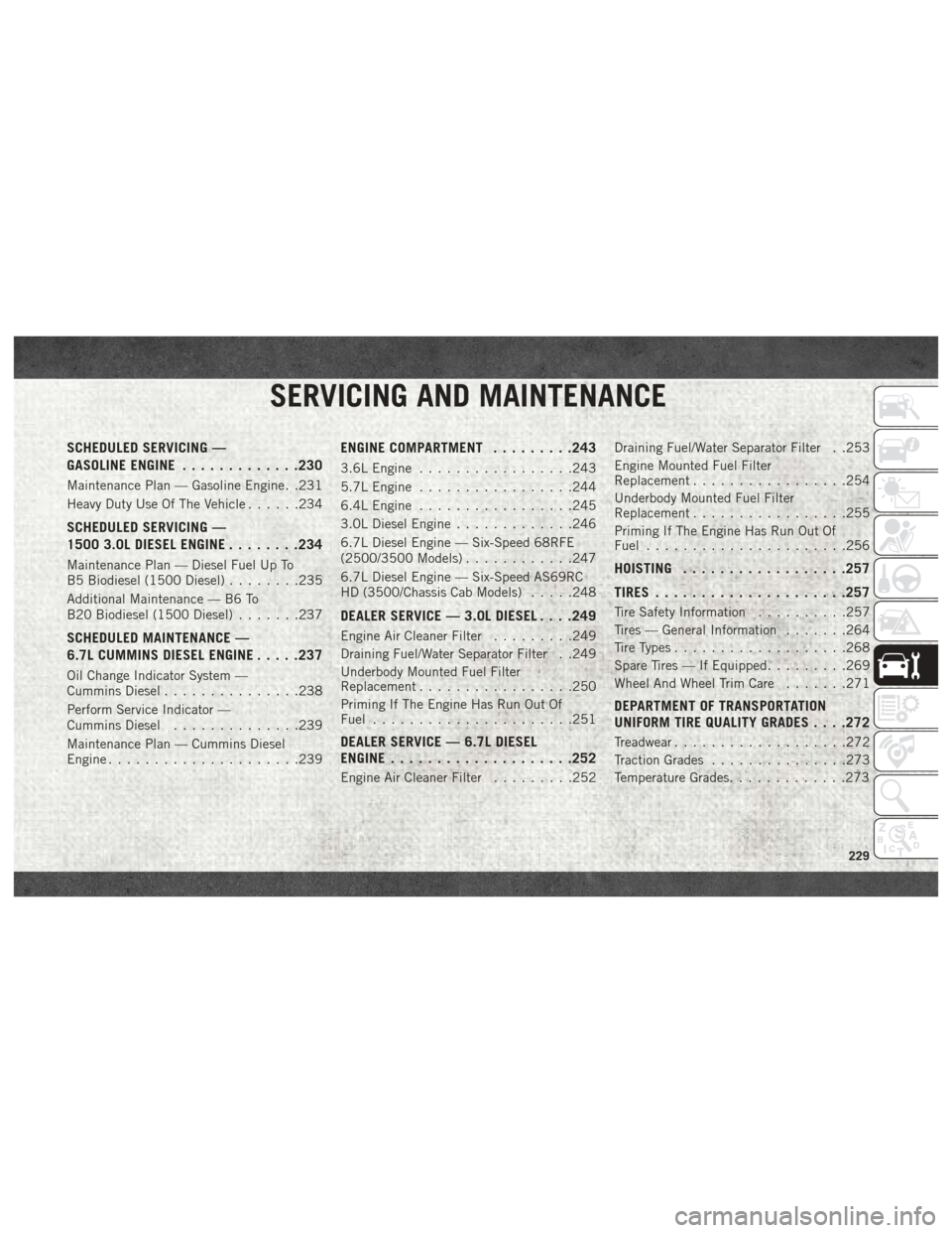
SCHEDULED SERVICING —
GASOLINE ENGINE.............230
Maintenance Plan — Gasoline Engine. .231
Heavy Duty Use Of The Vehicle ......234
SCHEDULED SERVICING —
1500 3.0L DIESEL ENGINE........234
Maintenance Plan — Diesel Fuel Up To
B5 Biodiesel (1500 Diesel) ........235
Additional Maintenance — B6 To
B20 Biodiesel (1500 Diesel) .......237
SCHEDULED MAINTENANCE —
6.7L CUMMINS DIESEL ENGINE .....237
Oil Change Indicator System —
Cummins Diesel...............238
Perform Service Indicator —
Cummins Diesel ..............239
Maintenance Plan — Cummins Diesel
Engine .....................239
ENGINE COMPARTMENT .........243
3.6L Engine.................243
5.7L Engine .................244
6.4L Engine .................245
3.0L Diesel Engine .............246
6.7L Diesel Engine — Six-Speed 68RFE
(2500/3500 Models) ............247
6.7L Diesel Engine — Six-Speed AS69RC
HD (3500/Chassis Cab Models) .....248
DEALER SERVICE — 3.0L DIESEL . . . .249
Engine Air Cleaner Filter.........249
Draining Fuel/Water Separator Filter . .249
Underbody Mounted Fuel Filter
Replacement .................250
Priming If The Engine Has Run Out Of
Fuel ......................251
DEALER SERVICE — 6.7L DIESEL
ENGINE ................... .252
Engine Air Cleaner Filter.........252Draining Fuel/Water Separator Filter . .253
Engine Mounted Fuel Filter
Replacement
.................254
Underbody Mounted Fuel Filter
Replacement .................255
Priming If The Engine Has Run Out Of
Fuel ......................256
HOISTING ................. .257
TIRES .................... .257
Tire Safety Information..........257
Tires — General Information .......264
Tire Types ...................268
Spare Tires — If Equipped .........269
Wheel And Wheel Trim Care .......271
DEPARTMENT OF TRANSPORTATION
UNIFORM TIRE QUALITY GRADES . . . .272
Treadwear...................272
Traction Grades ...............273
Temperature Grades .............273
SERVICING AND MAINTENANCE
229
Page 232 of 372
SCHEDULED SERVICING — GASOLINE
ENGINE
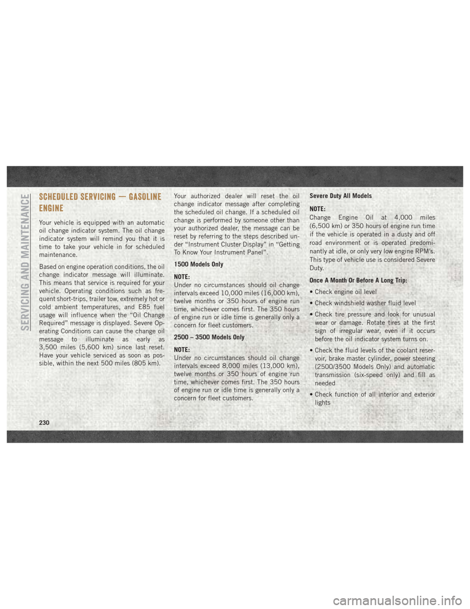
Your vehicle is equipped with an automatic
oil change indicator system. The oil change
indicator system will remind you that it is
time to take your vehicle in for scheduled
maintenance.
Based on engine operation conditions, the oil
change indicator message will illuminate.
This means that service is required for your
vehicle. Operating conditions such as fre-
quent short-trips, trailer tow, extremely hot or
cold ambient temperatures, and E85 fuel
usage will influence when the “Oil Change
Required” message is displayed. Severe Op-
erating Conditions can cause the change oil
message to illuminate as early as
3,500 miles (5,600 km) since last reset.
Have your vehicle serviced as soon as pos-
sible, within the next 500 miles (805 km).Your authorized dealer will reset the oil
change indicator message after completing
the scheduled oil change. If a scheduled oil
change is performed by someone other than
your authorized dealer, the message can be
reset by referring to the steps described un-
der “Instrument Cluster Display” in “Getting
To Know Your Instrument Panel”.
1500 Models Only
NOTE:
Under no circumstances should oil change
intervals exceed 10,000 miles (16,000 km),
twelve months or 350 hours of engine run
time, whichever comes first. The 350 hours
of engine run or idle time is generally only a
concern for fleet customers.
2500 – 3500 Models Only
NOTE:
Under no circumstances should oil change
intervals exceed 8,000 miles (13,000 km),
twelve months or 350 hours of engine run
time, whichever comes first. The 350 hours
of engine run or idle time is generally only a
concern for fleet customers. Severe Duty All Models
NOTE:
Change Engine Oil at 4,000 miles
(6,500 km) or 350 hours of engine run time
if the vehicle is operated in a dusty and off
road environment or is operated predomi-
nantly at idle, or only very low engine RPM’s.
This type of vehicle use is considered Severe
Duty.
Once A Month Or Before A Long Trip:
• Check engine oil level
• Check windshield washer fluid level
• Check tire pressure and look for unusual
wear or damage. Rotate tires at the first
sign of irregular wear, even if it occurs
before the oil indicator system turns on.
• Check the fluid levels of the coolant reser- voir, brake master cylinder, power steering
(2500/3500 Models Only) and automatic
transmission (six-speed only) and fill as
needed
• Check function of all interior and exterior lights
SERVICING AND MAINTENANCE
230
Page 233 of 372
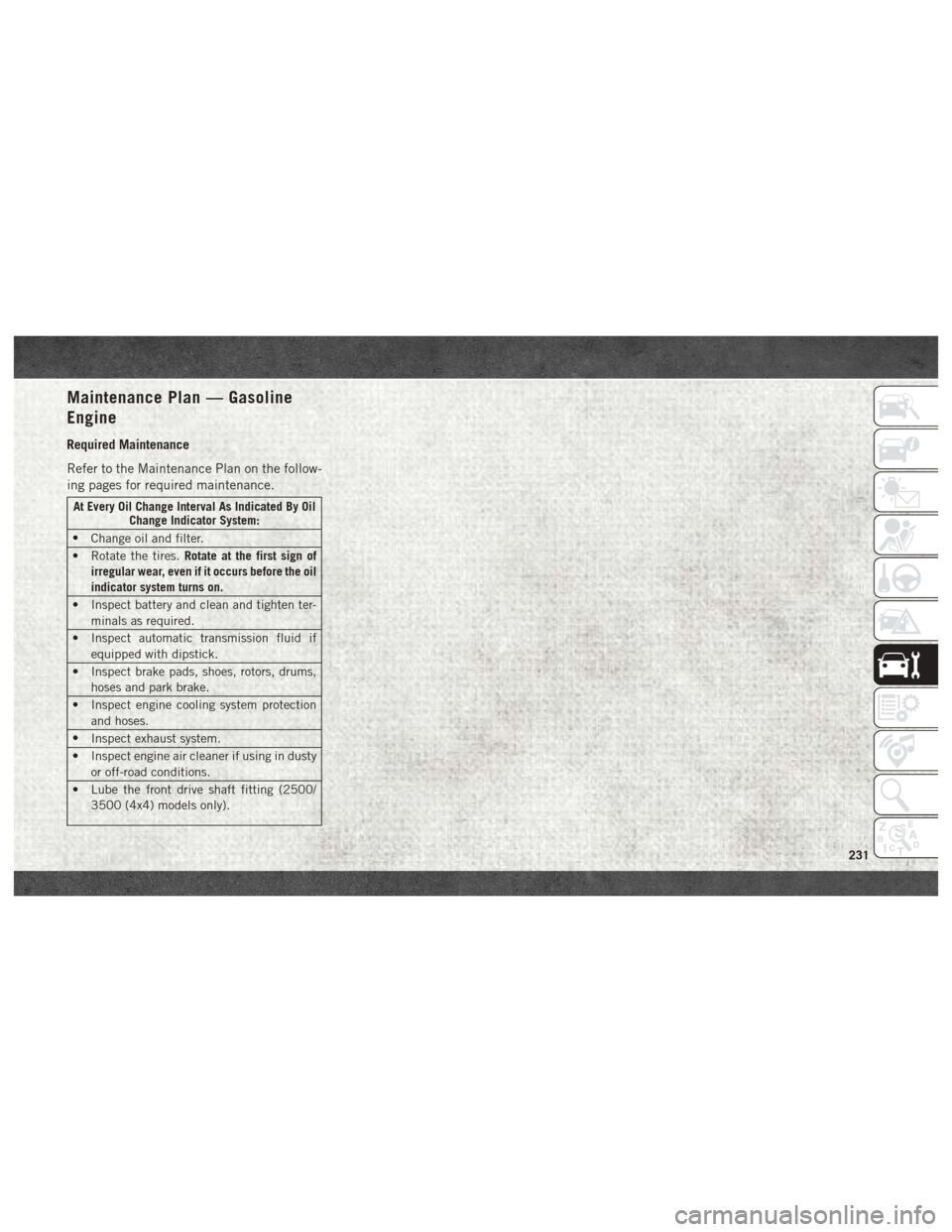
Maintenance Plan — Gasoline
Engine
Required Maintenance
Refer to the Maintenance Plan on the follow-
ing pages for required maintenance.
At Every Oil Change Interval As Indicated By OilChange Indicator System:
• Change oil and filter.
• Rotate the tires. Rotate at the first sign of
irregular wear, even if it occurs before the oil
indicator system turns on.
• Inspect battery and clean and tighten ter- minals as required.
• Inspect automatic transmission fluid if equipped with dipstick.
• Inspect brake pads, shoes, rotors, drums, hoses and park brake.
• Inspect engine cooling system protection and hoses.
• Inspect exhaust system.
• Inspect engine air cleaner if using in dusty or off-road conditions.
• Lube the front drive shaft fitting (2500/ 3500 (4x4) models only).
231
Page 234 of 372

Mileage or time passed (whichever comesfirst)
20,000
30,000
40,000
50,000
60,000
70,000
80,000
90,000
100,000
110,000
120,000
130,000
140,000
150,000
Or Years: 2 3 4 5 6 7 8 9 10 11 12 13 14 15
Or Kilometers:
32,000
48,000
64,000
80,000
96,000
112,000
128,000
144,000
160,000
176,000
192,000
208,000
224,000
240,000
Additional Inspections
Inspect the CV/Universal joints. X X X X X
Inspect front suspension, tie rod ends, and
replace if necessary. XXX X X X X
1500 Models:
Inspect the front and rear axle surfaces. If
gear oil leakage is suspected, check the
fluid level. If using your vehicle for police,
taxi, fleet, off-road or frequent trailer tow-
ing, change axle fluid. XX X X X
2500/3500 Models:
Inspect the front and rear axle surfaces. If
gear oil leakage is suspected, check the
fluid level. If using your vehicle for police,
taxi, fleet, off-road or frequent trailer tow-
ing, change axle fluid. XXX X X X X
Inspect the brake linings, replace as neces-
sary. XXX X X X X
Adjust parking brake as necessary. XXX X X XX
Inspect transfer case fluid. XX X
Additional Maintenance
Replace cabin air filter. XXX X X XX
SERVICING AND MAINTENANCE
232
Page 236 of 372
WARNING!
• You can be badly injured working on oraround a motor vehicle. Do only service
work for which you have the knowledge
and the right equipment. If you have any
doubt about your ability to perform a
service job, take your vehicle to a com-
petent mechanic.
• Failure to properly inspect and maintain
your vehicle could result in a component
malfunction and effect vehicle handling
and performance. This could cause an
accident.
Heavy Duty Use Of The Vehicle
Change engine oil at 4,000 miles (6,500 km)
or 350 hours of engine run time if the vehicle
is operated in a dusty and off road environ-
ment or is operated predominately at idle or
only very low engine RPM’s. This type of
vehicle use is considered Severe Duty.
SCHEDULED SERVICING — 1500 3.0L
DIESEL ENGINE
Your vehicle is equipped with an automatic
oil change indicator system. The oil change
indicator system will remind you that it is
time to take your vehicle in for scheduled
maintenance.
Based on engine operation conditions, the oil
change indicator message will illuminate.
This means that service is required for your
vehicle. Operating conditions such as fre-
quent short-trips, trailer tow, extremely hot or
cold ambient temperatures will influence
when the “Oil Change Required” message is
displayed. Severe Operating Conditions will
cause the change oil message to illuminate
more frequently. Have your vehicle serviced
as soon as possible, within the next
500 miles (805 km). Your authorized dealer will reset the oil
change indicator message after completing
the scheduled oil change. If a scheduled oil
change is performed by someone other than
your authorized dealer, the message can be
reset by referring to the steps described un-
der “Instrument Cluster Display” in “Getting
To Know Your Instrument Panel” in your Own-
er’s Manual for further information.
NOTE:
Under no circumstances should oil change
intervals exceed 10,000 miles (16,000 km)
or twelve months, whichever comes first.
Once A Month Or Before A Long Trip:
• Check engine oil level
• Check windshield washer fluid level
• Check the tire inflation pressures and look
for unusual wear or damage
• Check the fluid levels of the coolant reser- voir, brake master cylinder, and power
steering, and fill as needed
• Check function of all interior and exterior lights
SERVICING AND MAINTENANCE
234