air condition Ram 2500 2018 Owner's Manual
[x] Cancel search | Manufacturer: RAM, Model Year: 2018, Model line: 2500, Model: Ram 2500 2018Pages: 372, PDF Size: 7.1 MB
Page 177 of 372

Normal Ride Height (NRH)– This is the stan-
dard position of the suspension and is meant
for normal driving. It will automatically adjust
to maintain the rear ride height as conditions
change.
Alternate Trailer Height (ATH) – Lowers the
vehicle approximately 1 in (25 mm) for a
level truck, to be used as required while
trailer towing. It will automatically adjust to
maintain the rear ride height as conditions
change.
Trailer Decoupling/Unloading - The air suspen-
sion system will load level (lower/exhaust
only) for up to 10 minutes after the vehicle is
turned off. This allows for easy removal of a trailer and/or load from the back of the truck
by maintaining the ride height. After 10 min-
utes you will need to turn the ignition to the
run position for the air suspension to main-
tain ride height. If the air suspension system
is disabled using the settings menu (Tire Jack
Mode, Transport Mode or Alignment Mode)
the system will remain disabled when the
vehicle is turned off. Reactivating the air
suspension can be accomplished via the set-
tings menu or driving the vehicle above
5 mph (8 km/h) for Tire Jack Mode or Align-
ment Mode and 16 mph (26 km/h) for Trans-
port Mode.
NOTE:
• Most 3500 models will not lower to Alter-
nate Trailer Height (ATH) when unloaded.
• Refer to “Trailer Towing” in “Starting And Operating” for further information.
Ignition OFF Behavior
For a predetermined amount of time after the
ignition is off the air suspension may adjust
to maintain a proper appearance.
Refer to your Owner’s Manual for further
information.
WARNING!
The air suspension system uses a high
pressure volume of air to operate the sys-
tem. To avoid personal injury or damage to
the system, see your authorized dealer for
service.
Air Suspension Modes
The air suspension system has multiple
modes to protect the system in unique situa-
tions:
Tire/Jack Mode
To assist with changing a tire, the air suspen-
sion system has a feature which allows the
automatic leveling to be disabled. This mode
is intended to be enabled with engine run-
ning. Refer to “Instrument Cluster Display”
in “Getting To Know Your Instrument Panel”
or “Uconnect Settings” in “Multimedia” if
equipped with a touch screen radio, in your
Owner’s Manual for further information.
NOTE:
This mode is intended to be enabled with
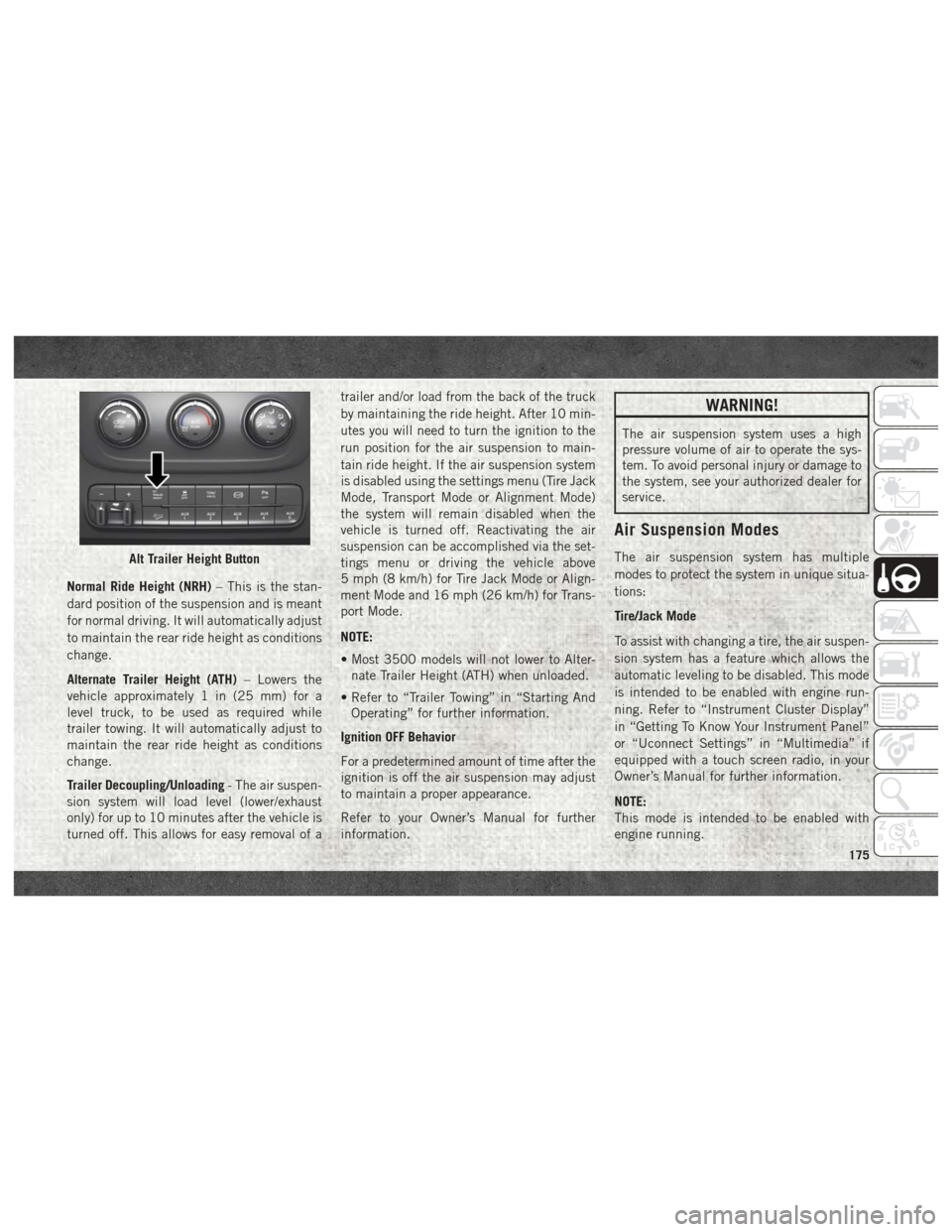
engine running.Alt Trailer Height Button
175
Page 198 of 372

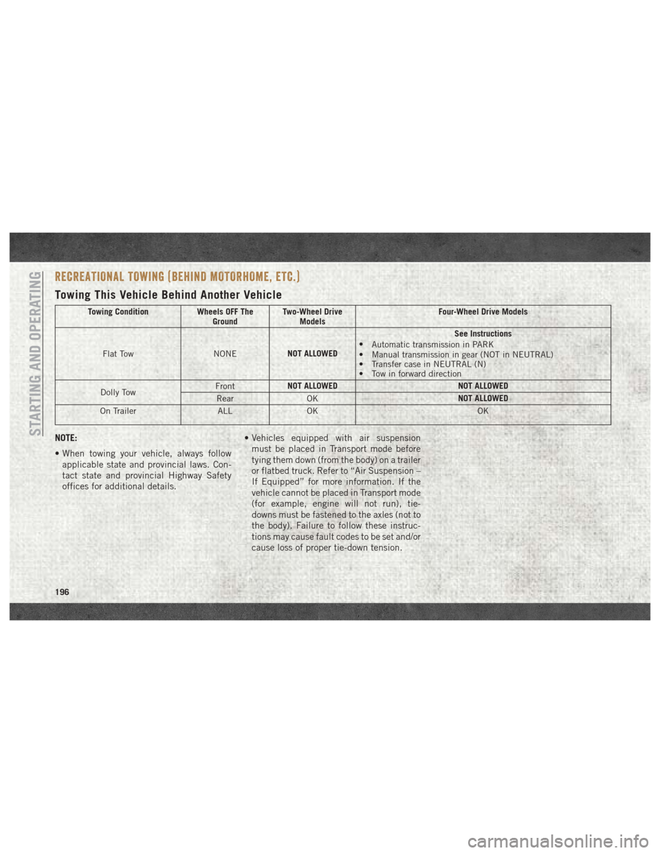
RECREATIONAL TOWING (BEHIND MOTORHOME, ETC.)
Towing This Vehicle Behind Another Vehicle
Towing ConditionWheels OFF The
Ground Two-Wheel Drive
Models Four-Wheel Drive Models
Flat Tow NONENOT ALLOWED See Instructions
• Automatic transmission in PARK
• Manual transmission in gear (NOT in NEUTRAL)
• Transfer case in NEUTRAL (N)
• Tow in forward direction
Dolly Tow Front
NOT ALLOWED
NOT ALLOWED
Rear OK NOT ALLOWED
On Trailer ALLOK OK
NOTE:
• When towing your vehicle, always follow
applicable state and provincial laws. Con-
tact state and provincial Highway Safety
offices for additional details. • Vehicles equipped with air suspension
must be placed in Transport mode before
tying them down (from the body) on a trailer
or flatbed truck. Refer to “Air Suspension –
If Equipped” for more information. If the
vehicle cannot be placed in Transport mode
(for example, engine will not run), tie-
downs must be fastened to the axles (not to
the body). Failure to follow these instruc-
tions may cause fault codes to be set and/or
cause loss of proper tie-down tension.STARTING AND OPERATING
196
Page 208 of 372

CavityCartridge Fuse Micro Fuse Description
F52 –5 Amp Tan Battery Sensor
F53 –20 Amp Yellow Trailer Tow – Left Turn/Stop Lights
F54 –20 Amp Yellow Adjustable Pedals
F56 –15 Amp Blue Additional Diesel Content – If Equipped
F57 –20 Amp Yellow Transmission
F58 –20 Amp Yellow Spare Fuse
F59 –10 Amp Red SCR Relay – If Equipped
F60 –15 Amp Blue Underhood Lamp
F61 –10 Amp Red (1500 LD Die-
sel & Cummins Diesel) PM Sensor – If Equipped
F62 –10 Amp Red Air Conditioning Clutch
F63 –20 Amp Yellow Ignition Coils (Gas), Urea Heater (Cummins Diesel)
F64 –25 Amp Clear Fuel Injectors / Powertrain
F65 –– Spare Fuse
F66 –10 Amp Red Sunroof / Passenger Window Switches / Rain Sensor
F67 –10 Amp Red CD / DVD / Bluetooth Hands-free Module – If Equipped
F69 –15 Amp Blue Mod SCR 12V (Cummins Diesel) – If Equipped
F70 –30 Amp Green Fuel Pump Motor
F71 –25 Amp Clear Amplifier
F72 –10 Amp Red PCM – If Equipped
F73 –20 Amp Yellow Fuel Transfer Pump (HD Only) – If Equipped
F74 –20 Amp Yellow (Gas Engine
& 1500 LD Diesel) Brake Vacuum Pump Gas/Diesel – If Equipped
IN CASE OF EMERGENCY
206
Page 222 of 372

WARNING!
personal injury. Only use the specific
ground point, do not use any other exposed
metal parts.
5. Start the engine in the vehicle that has the booster battery, let the engine idle a
few minutes, and then start the engine in
the vehicle with the discharged battery.
CAUTION!
Do not connect jumper cable to any of the
fuses on the positive battery terminal. The
resulting electrical current will blow the
fuse.
6. Once the engine is started, remove the jumper cables in the reverse sequence:
Disconnecting The Jumper Cables
1. Disconnect the negative (-)end of the
jumper cable from the engine ground of
the vehicle with the discharged battery. 2. Disconnect the opposite end of the nega-
tive (-)jumper cable from the negative (-)
post of the booster battery.
3. Disconnect the positive (+)end of the
jumper cable from the positive (+)post of
the booster battery.
4. Disconnect the opposite end of the posi- tive (+)jumper cable from the positive (+)
post of the vehicle with the discharged
battery.
If frequent jump starting is required to start
your vehicle you should have the battery and
charging system inspected at an authorized
dealer.
CAUTION!
Accessories plugged into the vehicle
power outlets draw power from the vehi-
cle’s battery, even when not in use (i.e.,
cellular devices, etc.). Eventually, if
plugged in long enough without engine
operation, the vehicle’s battery will dis-
charge sufficiently to degrade battery life
and/or prevent the engine from starting.
IF YOUR ENGINE OVERHEATS
In any of the following situations, you can
reduce the potential for overheating by taking
the appropriate action.
• On the highways — slow down.
• In city traffic — while stopped, place the transmission in NEUTRAL, but do not in-
crease the engine idle speed while prevent-
ing vehicle motion with the brakes.
NOTE:
There are steps that you can take to slow
down an impending overheat condition:
• If your air conditioner (A/C) is on, turn it off. The A/C system adds heat to the engine
cooling system and turning the A/C off can
help remove this heat.
• You can also turn the temperature control to maximum heat, the mode control to floor
and the blower control to high. This allows
the heater core to act as a supplement to
the radiator and aids in removing heat from
the engine cooling system.
IN CASE OF EMERGENCY
220
Page 223 of 372

WARNING!
You or others can be badly burned by hot
engine coolant (antifreeze) or steam from
your radiator. If you see or hear steam
coming from under the hood, do not open
the hood until the radiator has had time to
cool. Never try to open a cooling system
pressure cap when the radiator or coolant
bottle is hot.
CAUTION!
Driving with a hot cooling system could
damage your vehicle. If the temperature
gauge reads HOT (H), pull over and stop
the vehicle. Idle the vehicle with the air
conditioner turned off until the pointer
drops back into the normal range. If the
pointer remains on HOT (H), and you hear
continuous chimes, turn the engine off
immediately and call for service.
GEAR SELECTOR OVERRIDE —
6-SPEED TRANSMISSION
If a malfunction occurs and the gear selector
cannot be moved out of the PARK position,
you can use one of the following procedures
to temporarily move the gear selector.
Column Gear Selector — If
Equipped
1. Turn the engine OFF.
2. Firmly apply the parking brake.
3. Tilt the steering wheel to the full upposition.
4. Press and maintain firm pressure on the brake pedal.
5. Insert a screwdriver or similar tool into the access port (ringed circle) on the bottom
of the steering column, and push and hold
the override release lever up. 6. Move the gear selector to the NEUTRAL
position.
7. The vehicle may then be started in NEUTRAL.
Shift Lock Manual Override Access Port
221
Page 227 of 372

TOWING A DISABLED VEHICLE
This section describes procedures for towing
a disabled vehicle using a commercial towing
service. If the transmission and drivetrain are
operable, disabled vehicles may also be
towed as described under “Recreational Tow-
ing” in the “Starting And Operating” section.NOTE:
Vehicles equipped with air suspension must
be placed in Transport mode, before tying
them down (from the body) on a trailer or
flatbed truck. Refer to "Air Suspension" in
"Starting And Operating" for more informa-
tion. If the vehicle cannot be placed in Trans-
port mode (for example, engine will not run),
tie-downs must be fastened to the axles (not
to the body). Failure to follow these instruc-
tions may cause fault codes to be set and/or
cause loss of proper tie-down tension.
Towing Condition Wheels OFF The Ground
2WD Models4WD Models
Flat Tow NONE If transmission is operable:
• Transmission in NEUTRAL
• 30 mph (48 km/h) max
• 15 miles (24 km) maxdistance •
Auto Transmission in PARK
• Manual Transmission in gear
(NOT NEUTRAL)
• Transfer Case in NEUTRAL
• Tow in FORWARDdirection
Wheel Lift Or Dolly Tow Front
NOT ALLOWED
Rear OK
NOT ALLOWED
Flatbed ALL
BEST METHOD BEST METHOD
CAUTION!
• Do not use sling type equipment when
towing. Vehicle damage may occur.
CAUTION!
•When securing the vehicle to a flat bed
truck, do not attach to front or rear sus-
CAUTION!
pension components. Damage to your ve-
hicle may result from improper towing.
225
Page 233 of 372

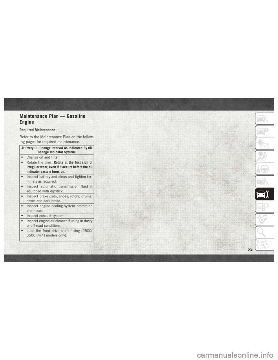
Maintenance Plan — Gasoline
Engine
Required Maintenance
Refer to the Maintenance Plan on the follow-
ing pages for required maintenance.
At Every Oil Change Interval As Indicated By OilChange Indicator System:
• Change oil and filter.
• Rotate the tires. Rotate at the first sign of
irregular wear, even if it occurs before the oil
indicator system turns on.
• Inspect battery and clean and tighten ter- minals as required.
• Inspect automatic transmission fluid if equipped with dipstick.
• Inspect brake pads, shoes, rotors, drums, hoses and park brake.
• Inspect engine cooling system protection and hoses.
• Inspect exhaust system.
• Inspect engine air cleaner if using in dusty or off-road conditions.
• Lube the front drive shaft fitting (2500/ 3500 (4x4) models only).
231
Page 237 of 372

Maintenance Plan — Diesel Fuel
Up To B5 Biodiesel (1500 Diesel)
Required Maintenance
Refer to the Maintenance Schedules on the
following pages for required maintenance.
At Every Oil Change Interval As Indicated By OilChange Indicator System:
• Change oil and filter.
•
Completely fill the Diesel Exhaust Fluid tank.
• Drain water from fuel filter assembly.
• Rotate the tires. Rotate at the first sign of
irregular wear, even if it occurs before the oil
indicator system turns on.
• Inspect battery and clean and tighten ter- minals as required.
• Inspect brake pads, shoes, rotors, drums, hoses and park brake.
• Inspect engine cooling system protection and hoses.
• Inspect exhaust system.
• Inspect engine air cleaner if using in dusty or off-road conditions.
At Every Second Oil Change Interval As Indi-cated By Oil Change Indicator System:
• Change fuel filter.
235
Page 253 of 372

5. Remove bottom cover using a strapwrench. Rotate counterclockwise for re-
moval. Remove the used o-ring and dis-
card it.
6. Remove the used filter cartridge from the housing and dispose of it according to
your local regulations.
7. Wipe the sealing surfaces of the lid and housing clean.
8. Install a new o-ring into the ring groove on the filter housing and lubricate with clean
engine oil.
NOTE:
WIF (Water In Fuel) sensor is re-usable. Ser-
vice kit comes with new o-ring for filter can-
ister and WIF sensor.
Priming If The Engine Has Run Out
Of Fuel
WARNING!
Do not open the high pressure fuel system
with the engine running. Engine operation
causes high fuel pressure. High pressure
WARNING!
fuel spray can cause serious injury or
death.
1. Add a substantial amount of fuel to the tank, approximately 2 to 5 gal (8L to
19L).
2. Press ignition switch twice without your foot on brake to put vehicle in Run posi-
tion. This will activate the in tank fuel
pump for approximately 30 seconds. Re-
peat this process twice.
3. Start the engine using the “Normal Start- ing” procedure. Refer to “Starting The
Engine” in “Starting and Operating” for
further information.
CAUTION!
The starter motor will engage for approxi-
mately 30 seconds at a time. Allow two
minutes between cranking intervals.
NOTE:
The engine may run rough until the air is
forced from all the fuel lines.
WARNING!
Do not use alcohol or gasoline as a fuel
blending agent. They can be unstable un-
der certain conditions and be hazardous or
explosive when mixed with diesel fuel.
CAUTION!
Due to lack of lubricants in alcohol or
gasoline, the use of these fuels can cause
damage to the fuel system.
NOTE:
• Use of biodiesel mixture in excess of 20% can negatively impact the fuel filter's abil-
ity to separate water from the fuel, resulting
in high pressure fuel system corrosion or
damage.
• In addition, commercially available fuel ad- ditives are not necessary for the proper
operation of your diesel engine.
• For extreme cold conditions, "Mopar Pre- mium Diesel Fuel Treatment" is recom-
mended to assist with cold starting.
251
Page 254 of 372

DEALER SERVICE — 6.7L DIESEL
ENGINE
Your authorized dealer has the qualified ser-
vice personnel, special tools, and equipment
to perform all service operations in an expert
manner. Service Manuals are available which
include detailed service information for your
vehicle. Refer to these Service Manuals be-
fore attempting any procedure yourself.
NOTE:
Intentional tampering with emissions control
systems may void your warranty and could
result in civil penalties being assessed
against you.
WARNING!
You can be badly injured working on or
around a motor vehicle. Only do service
work for which you have the knowledge
and the proper equipment. If you have any
doubt about your ability to perform a ser-
vice job, take your vehicle to a competent
mechanic.
Engine Air Cleaner Filter
CAUTION!
All air entering the engine intake must be
filtered. The abrasive particles in unfil-
tered air will cause rapid wear to engine
components.
WARNING!
The air induction system (air cleaner,
hoses, etc.) provides a measure of protec-
tion. Do not remove the air induction sys-
tem (air cleaner, hoses, etc.) unless such
removal is necessary for repair or mainte-
nance. Make sure that no one is near the
engine compartment before starting the
vehicle with the air induction system (air
cleaner, hoses, etc.) removed. Failure to
do so can result in serious personal injury.
The condition of the air cleaner filter is moni-
tored by the Engine Control Module. The
“SERVICE AIR FILTER” message will display
in the instrument cluster when service is required. Refer to “Instrument Cluster Dis-
play” in “Getting To Know Your Instrument
Panel” for further information.
The “SERVICE AIR FILTER” message could
be displayed periodically. This is because
engine air flow requirements change based
on driving conditions. As the filter becomes
more restrictive and air flow requirements
increase the “SERVICE AIR FILTER” mes-
sage will be displayed. The message may not
be displayed in subsequent drive cycles if the
same conditions are not met. The air filter
element should be replaced within 250 miles
(402 km) from the first time this message is
displayed to ensure proper engine operation
during all driving conditions.
CAUTION!
Driving with a restricted air filter can
cause engine damage. Driving in dusty
environments for extended periods will
lead to rapid air filter plugging. Action
should be taken as soon as the “SERVICE
AIR FILTER” message is displayed.
SERVICING AND MAINTENANCE
252