stop start Ram 2500 2020 Owner's Manual
[x] Cancel search | Manufacturer: RAM, Model Year: 2020, Model line: 2500, Model: Ram 2500 2020Pages: 553, PDF Size: 21.99 MB
Page 7 of 553

5
STARTING AND OPERATING
STARTING THE ENGINE — GAS ENGINE ......... 211Automatic Transmission ............................211
Tip Start Feature .......................................211
Keyless Enter-N-Go — Ignition ...................211
Normal Starting Using ENGINE START/
STOP Button ...............................................212 Cold Weather Operation (Below –22°F Or
−30°C) ......................................................215 After Starting ..............................................215
STARTING THE ENGINE — DIESEL ENGINE..... 215
Automatic Transmission ............................215
Keyless Enter-N-Go — Ignition ...................216
Extreme Cold Weather...............................218
Normal Starting Procedure — Engine
Manifold Air Temperature Above 66° F
(19° C)........................................................ 218 Starting Procedure — Engine Manifold Air
Temperature 0°F To 66°F (–18°C to
19°C) ..........................................................219 Starting Procedure — Engine Manifold Air
Temperature Below 0°F (-18°C) ..............220 Starting Fluids ............................................221 NORMAL OPERATION — DIESEL ENGINE ........221
Cold Weather Precautions ........................ 222
Engine Idling ............................................. 224
Noise........................................................... 225
Stopping The Engine ................................. 225
Idle Shutdown ............................................ 226
Programmable Maximum Vehicle
Speed ......................................................... 226 Operating Precautions............................... 226
Cooling System Tips .................................. 226
ENGINE BLOCK HEATER — GAS ENGINE (IF
EQUIPPED) ..........................................................227
ENGINE BLOCK HEATER — DIESEL ENGINE (IF
EQUIPPED) ......................................................... 227
Block Heater Usage ................................... 228
ENGINE BREAK-IN RECOMMENDATIONS — GAS
ENGINE ................................................................ 228
ENGINE BREAK-IN RECOMMENDATIONS —
DIESEL ENGINE...................................................228
PARKING BRAKE ............................................... 229
DIESEL EXHAUST BRAKE — ENGINE BRAKING
(IF EQUIPPED) ....................................................230
AUTOMATIC TRANSMISSION ........................... 231
Ignition Park Interlock ............................... 232
Brake/Transmission Shift Interlock
System ....................................................... 232 Eight-Speed Automatic Transmission — If
Equipped .................................................... 233 Six-Speed Automatic Transmission — If
Equipped .................................................... 237
AUXILIARY SWITCHES — IF EQUIPPED ........... 243
ACTIVE NOISE CANCELLATION ........................ 243
FOUR-WHEEL DRIVE OPERATION —
IF EQUIPPED ...................................................... 244
Four-Position Electronically Shifted Transfer
Case — If Equipped ................................... 244
Manually Shifted Transfer Case —
If Equipped ................................................. 247
AIR SUSPENSION SYSTEM — IF EQUIPPED.... 250
Description ................................................. 250
Air Suspension Modes .............................. 251
Instrument Cluster Display Messages ..... 251
Operation ................................................... 251
AXLE LOCKER SYSTEM — POWER WAGON
MODELS ONLY (IF EQUIPPED) ......................... 252
STABILIZER/SWAY BAR SYSTEM — POWER
WAGON ONLY .................................................... 253
20_DJD2_OM_EN_USC_t.book Page 5
Page 16 of 553
14GETTING TO KNOW YOUR VEHICLE
TIP:
When viewing a topic, tap the star icon to add it
to your Favorites, for easy access in the future.
KEYS
Key Fob
Your vehicle uses a keyless ignition system. The
ignition system consists of a key fob and a
START/STOP push button ignition system. The
Remote Keyless Entry (RKE) system consists of
a key fob and Keyless Enter-N-Go feature.
NOTE:
The key fob may not be found if it is located next
to a mobile phone, laptop or other electronic
device; these devices may block the key fob’s
wireless signal.
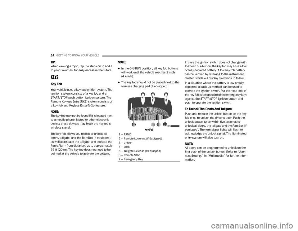
The key fob allows you to lock or unlock all
doors, tailgate, and the RamBox (if equipped),
as well as release the tailgate, and activate the
Panic Alarm from distances up to approximately
66 ft (20 m). The key fob does not need to be
pointed at the vehicle to activate the system. NOTE:
In the ON/RUN position, all key fob buttons
will work until the vehicle reaches 2 mph
(4 km/h).
The key fob should not be placed next to the
wireless charging pad (if equipped).
Key Fob
In case the ignition switch does not change with
the push of a button, the key fob may have a low
or fully depleted battery. A low key fob battery
can be verified by referring to the instrument
cluster, which will display directions to follow.
In a situation where the battery is low or fully
depleted, a back up method can be used to
operate the ignition switch. Put the nose side of
the key fob (side opposite of the emergency key)
against the START/STOP ignition button and
push to operate the ignition switch.
To Unlock The Doors And Tailgate
Push and release the unlock button on the key
fob once to unlock the driver’s door. Push the
unlock button twice within five seconds to
unlock all doors, the tailgate and the RamBox (if
equipped). The turn signal lights will flash to
acknowledge the unlock signal. The illuminated
entry system will also turn on.
NOTE:
All doors can be programmed to unlock on the
first push of the unlock button. Refer to “Ucon
-
nect Settings” in “Multimedia” for further infor -
mation.
1 — PANIC
2 — Remote Lowering (If Equipped)
3 — Unlock
4 — Lock
5 — Tailgate Release (If Equipped)
6 — Remote Start
7 — Emergency Key
20_DJD2_OM_EN_USC_t.book Page 14
Page 20 of 553
18GETTING TO KNOW YOUR VEHICLE
Le présent appareil est conforme aux CNR
d`Innovation, Science and Economic Develop -
ment applicables aux appareils radio exempts
de licence. L'exploitation est autorisée aux deux
conditions suivantes:
1. l'appareil ne doit pas produire de brouil -
lage, et
2. l'utilisateur de l'appareil doit accepter tout brouillage radioélectrique subi, même si le
brouillage est susceptible d'en comprom -
ettre le fonctionnement.
La operación de este equipo está sujeta a las
siguientes dos condiciones:
1. es posible que este equipo o dispositivo no cause interferencia perjudicial y
2. este equipo o dispositivo debe aceptar cual -
quier interferencia, incluyendo la que
pueda causar su operación no deseada.
NOTE:
Changes or modifications not expressly
approved by the party responsible for compli -
ance could void the user’s authority to operate
the equipment.IGNITION SWITCH
Keyless Push Button Ignition
This feature allows the driver to operate the igni -
tion switch with the push of a button as long as
the Remote Keyless Entry key fob is in the
passenger compartment.
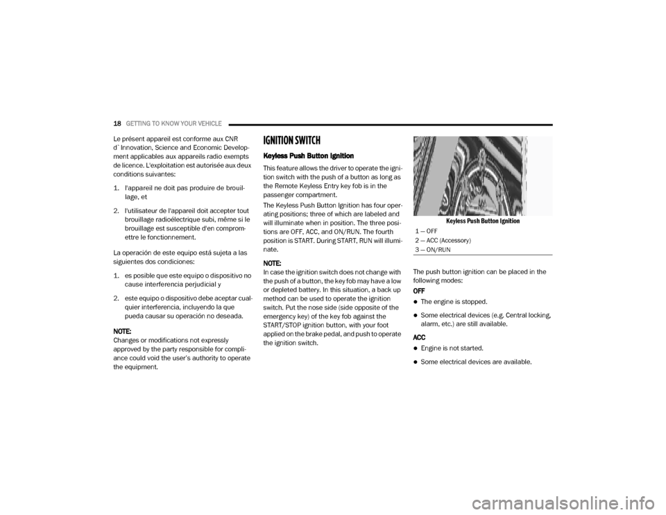
The Keyless Push Button Ignition has four oper -
ating positions; three of which are labeled and
will illuminate when in position. The three posi -
tions are OFF, ACC, and ON/RUN. The fourth
position is START. During START, RUN will illumi -
nate.
NOTE:
In case the ignition switch does not change with
the push of a button, the key fob may have a low
or depleted battery. In this situation, a back up
method can be used to operate the ignition
switch. Put the nose side (side opposite of the
emergency key) of the key fob against the
START/STOP ignition button, with your foot
applied on the brake pedal, and push to operate
the ignition switch.
Keyless Push Button Ignition
The push button ignition can be placed in the
following modes:
OFF
The engine is stopped.
Some electrical devices (e.g. Central locking,
alarm, etc.) are still available.
ACC
Engine is not started.
Some electrical devices are available.
1 — OFF
2 — ACC (Accessory)
3 — ON/RUN
20_DJD2_OM_EN_USC_t.book Page 18
Page 21 of 553
GETTING TO KNOW YOUR VEHICLE19
(Continued)
RUN
Driving position.
All the electrical devices are available.
START
The engine will start.
The engine only runs in the ON/RUN ignition
position or from a remote start request.
In case the ignition switch does not change with
the push of a button, the key fob may have a low
or depleted battery. In this situation, a back up
method can be used to operate the ignition
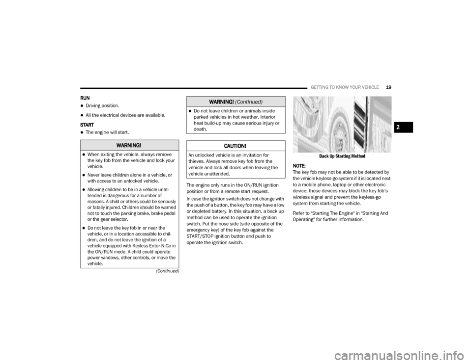
switch. Put the nose side (side opposite of the
emergency key) of the key fob against the
START/STOP ignition button and push to
operate the ignition switch.
Back Up Starting Method
NOTE:
The key fob may not be able to be detected by
the vehicle keyless-go system if it is located next
to a mobile phone, laptop or other electronic
device; these devices may block the key fob’s
wireless signal and prevent the keyless-go
system from starting the vehicle.
Refer to "Starting The Engine" in "Starting And
Operating" for further information.
WARNING!
When exiting the vehicle, always remove
the key fob from the vehicle and lock your
vehicle.
Never leave children alone in a vehicle, or
with access to an unlocked vehicle.
Allowing children to be in a vehicle unat -
tended is dangerous for a number of
reasons. A child or others could be seriously
or fatally injured. Children should be warned
not to touch the parking brake, brake pedal
or the gear selector.
Do not leave the key fob in or near the
vehicle, or in a location accessible to chil -
dren, and do not leave the ignition of a
vehicle equipped with Keyless Enter-N-Go in
the ON/RUN mode. A child could operate
power windows, other controls, or move the
vehicle.
Do not leave children or animals inside
parked vehicles in hot weather. Interior
heat build-up may cause serious injury or
death.
CAUTION!
An unlocked vehicle is an invitation for
thieves. Always remove key fob from the
vehicle and lock all doors when leaving the
vehicle unattended.
WARNING! (Continued)
2
20_DJD2_OM_EN_USC_t.book Page 19
Page 114 of 553
112GETTING TO KNOW YOUR INSTRUMENT PANEL
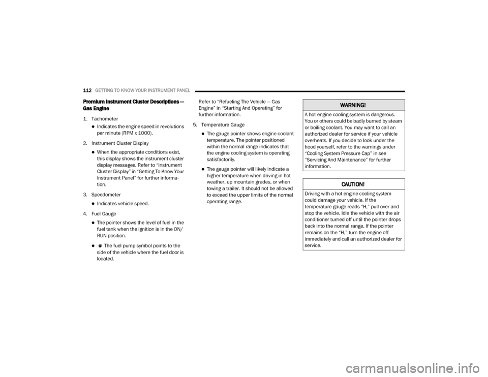
Premium Instrument Cluster Descriptions —
Gas Engine
1. Tachometer
Indicates the engine speed in revolutions
per minute (RPM x 1000).
2. Instrument Cluster Display
When the appropriate conditions exist, this display shows the instrument cluster
display messages. Refer to “Instrument
Cluster Display” in “Getting To Know Your
Instrument Panel” for further informa -
tion.
3. Speedometer
Indicates vehicle speed.
4. Fuel Gauge
The pointer shows the level of fuel in the fuel tank when the ignition is in the ON/
RUN position.
The fuel pump symbol points to the
side of the vehicle where the fuel door is
located. Refer to “Refueling The Vehicle — Gas
Engine” in “Starting And Operating” for
further information.
5. Temperature Gauge
The gauge pointer shows engine coolant temperature. The pointer positioned
within the normal range indicates that
the engine cooling system is operating
satisfactorily.
The gauge pointer will likely indicate a higher temperature when driving in hot
weather, up mountain grades, or when
towing a trailer. It should not be allowed
to exceed the upper limits of the normal
operating range.
WARNING!
A hot engine cooling system is dangerous.
You or others could be badly burned by steam
or boiling coolant. You may want to call an
authorized dealer for service if your vehicle
overheats. If you decide to look under the
hood yourself, refer to the warnings under
“Cooling System Pressure Cap” in see
“Servicing And Maintenance” for further
information.
CAUTION!
Driving with a hot engine cooling system
could damage your vehicle. If the
temperature gauge reads “H,” pull over and
stop the vehicle. Idle the vehicle with the air
conditioner turned off until the pointer drops
back into the normal range. If the pointer
remains on the “H,” turn the engine off
immediately and call an authorized dealer for
service.
20_DJD2_OM_EN_USC_t.book Page 112
Page 116 of 553
114GETTING TO KNOW YOUR INSTRUMENT PANEL
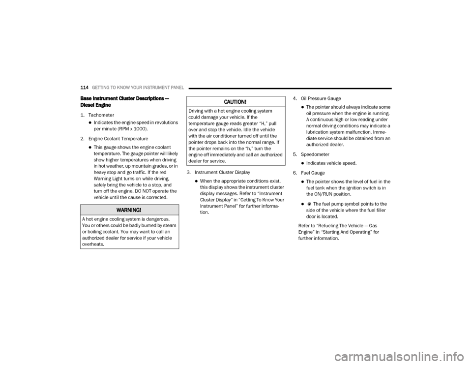
Base Instrument Cluster Descriptions —
Diesel Engine
1. Tachometer
Indicates the engine speed in revolutions
per minute (RPM x 1000).
2. Engine Coolant Temperature
This gauge shows the engine coolant temperature. The gauge pointer will likely
show higher temperatures when driving
in hot weather, up mountain grades, or in
heavy stop and go traffic. If the red
Warning Light turns on while driving,
safely bring the vehicle to a stop, and
turn off the engine. DO NOT operate the
vehicle until the cause is corrected. 3. Instrument Cluster Display
When the appropriate conditions exist,
this display shows the instrument cluster
display messages. Refer to “Instrument
Cluster Display” in “Getting To Know Your
Instrument Panel” for further informa -
tion. 4. Oil Pressure Gauge
The pointer should always indicate some
oil pressure when the engine is running.
A continuous high or low reading under
normal driving conditions may indicate a
lubrication system malfunction. Imme -
diate service should be obtained from an
authorized dealer.
5. Speedometer
Indicates vehicle speed.
6. Fuel Gauge
The pointer shows the level of fuel in the fuel tank when the ignition switch is in
the ON/RUN position.
The fuel pump symbol points to the
side of the vehicle where the fuel filler
door is located.
Refer to “Refueling The Vehicle — Gas
Engine” in “Starting And Operating” for
further information.
WARNING!
A hot engine cooling system is dangerous.
You or others could be badly burned by steam
or boiling coolant. You may want to call an
authorized dealer for service if your vehicle
overheats.
CAUTION!
Driving with a hot engine cooling system
could damage your vehicle. If the
temperature gauge reads greater “H,” pull
over and stop the vehicle. Idle the vehicle
with the air conditioner turned off until the
pointer drops back into the normal range. If
the pointer remains on the “h,” turn the
engine off immediately and call an authorized
dealer for service.
20_DJD2_OM_EN_USC_t.book Page 114
Page 121 of 553
GETTING TO KNOW YOUR INSTRUMENT PANEL119
Right Arrow Button
Push and release the right arrow
button to access/select the infor -
mation screens or submenu
screens of a main menu item. Push
and hold the right arrow button for two
seconds to reset displayed/selected features
that can be reset.
Left Arrow Button
Push and release the left arrow
button to access/select the infor -
mation screens, submenu screens
of a main menu item, or to return to
the main menu.
Oil Life Reset
Your vehicle is equipped with an engine oil
change indicator system. The “Oil Change
Required” message will display in the instru -
ment cluster display after a single chime has
sounded, to indicate the next scheduled oil
change interval. The engine oil change indicator
system is duty cycle based, which means the
engine oil change interval may fluctuate, depen -
dent upon your personal driving style. NOTE:
Use the steering wheel instrument cluster
display controls for the following procedure.
Oil Life Reset Procedure
1. Without pushing the brake pedal, push the
ENGINE START/STOP button and place the
ignition to the ON/RUN position (do not
start the engine).
2. Push and release the down arrow button to
scroll downward through the main menu to
“Vehicle Info.”
3. Push and release the right arrow button to
access the ”Vehicle Info” screen, then scroll
up or down to select “Oil Life.”
4. Push and hold the right arrow button to
select “Reset”.
5. Push and release the down arrow button to
select “Yes,” then push and release the
right arrow button to reset the Oil Life to
100%.
6. Push and release the up arrow button to exit
the instrument cluster display screen. Secondary Method Of Resetting Engine Oil Life
1. Without pressing the brake pedal, push the
ENGINE START/STOP button and place the
ignition to the ON/RUN position (do not
start the engine).
2. Fully press the accelerator pedal, slowly, three times within ten seconds.
3. Without pushing the brake pedal, push the ENGINE START/STOP button once to return
the ignition to the OFF/LOCK position.
NOTE:
If the indicator message illuminates when you
start the vehicle, the oil change indicator
system did not reset. If necessary, repeat this
procedure.Display Menu Items
Push and release the up or down arrow button
until the desired selectable menu icon is high -
lighted in the instrument cluster display.
Refer to “Instrument Cluster Display” in this
chapter for further information.
3
20_DJD2_OM_EN_USC_t.book Page 119
Page 130 of 553
128GETTING TO KNOW YOUR INSTRUMENT PANEL
value where it stopped when a previous fault
was temporarily remedied, or at a minimum of
50 miles (80 km).
5 MPH Max Speed on Restart, Long Idle or
Refuel Service DEF See Dealer — This
message will continuously display when the
mileage counter reaches zero, and will be
accompanied by a periodic chime.
The vehicle will only be capable of a
maximum speed of 5 MPH upon the first of
the following conditions to occur:
If the vehicle is shutoff and restarted.
If the vehicle is idled for an extended
period of time, approximately one hour or
greater.
If the system detects that the level of fuel in the tank has increased.
5 MPH Max Speed Service DEF System See
Dealer — This message will continuously
display, and will be accompanied by a peri -
odic chime. Although the vehicle can be
started and placed in gear, the vehicle will
only operate at a maximum speed of 5 MPH.
Your vehicle will require towing, see an
authorized dealer for service. NOTE:
When this message is displayed, the engine can
still be started. However, the vehicle will only
operate at a maximum speed of 5 MPH.
Incorrect DEF Detected See Dealer
— This
message will display when the fault is initially
detected, each time the vehicle is started,
and periodically during driving. The message
will be accompanied by a single chime. We
recommend you drive to your nearest autho -
rized dealer and have your vehicle serviced
as soon as possible.
RAM Active Air System
Your vehicle is equipped with an advanced Ram
Active Air system that provides enhanced
performance, especially when towing under
demanding hot or high altitude conditions. If the
instrument cluster display displays the
message “Active Airbox Service Required See
Dealer”, vehicle performance may be reduced
until service is performed by an authorized RAM
dealer.
Battery Saver On/Battery Saver Mode
Message — Electrical Load Reduction
Actions — If Equipped
This vehicle is equipped with an Intelligent
Battery Sensor (IBS) to perform additional moni -
toring of the electrical system and status of the
vehicle battery.
In cases when the IBS detects charging system
failure, or the vehicle battery conditions are
deteriorating, electrical load reduction actions
will take place to extend the driving time and
distance of the vehicle. This is done by reducing
power to or turning off non-essential electrical
loads.
Load reduction is only active when the engine is
running. It will display a message if there is a
risk of battery depletion to the point where the
vehicle may stall due to lack of electrical supply,
or will not restart after the current drive cycle.
When load reduction is activated, the message
“Battery Saver On Some Systems May Have
Reduced Power” will appear in the instrument
cluster.
These messages indicate the vehicle battery
has a low state of charge and continues to lose
electrical charge at a rate that the charging
system cannot sustain.
20_DJD2_OM_EN_USC_t.book Page 128
Page 132 of 553
130GETTING TO KNOW YOUR INSTRUMENT PANEL
After a trip:
Check if any aftermarket equipment was
installed (additional lights, upfitter electrical
accessories, audio systems, alarms) and
review specifications if any (load and Ignition
Off Draw currents).
Evaluate the latest driving cycles (distance,
driving time and parking time).
The vehicle should have service performed if
the message is still present during consecu-
tive trips and the evaluation of the vehicle
and driving pattern did not help to identify the
cause.
WARNING LIGHTS AND MESSAGES
The warning/indicator lights will illuminate in
the instrument panel together with a dedicated
message and/or acoustic signal when appli -
cable. These indications are indicative and
precautionary and as such must not be consid -
ered as exhaustive. Always refer to the informa-
tion in this chapter in the event of a failure
indication. All active telltales will display first if
applicable. The system check menu may
appear different based upon equipment
options and current vehicle status. Some tell -
tales are optional and may not appear.
Red Warning Lights
Seat Belt Reminder Warning Light
This warning light indicates when the
driver or passenger seat belt is
unbuckled. When the ignition is first
placed in the ON/RUN or ACC/ON/
RUN position and if the driver’s seat belt is
unbuckled, a chime will sound and the light will
turn on. When driving, if the driver or front
passenger seat belt remains unbuckled, the
Seat Belt Reminder Light will flash or remain on
continuously and a chime will sound.
Refer to “Occupant Restraint Systems” in
“Safety” for further information.
Air Bag Warning Light
This warning light will illuminate to
indicate a fault with the air bag, and
will turn on for four to eight seconds
as a bulb check when the ignition is
placed in the ON/RUN or ACC/ON/RUN posi -
tion. This light will illuminate with a single chime
when a fault with the air bag has been detected,
it will stay on until the fault is cleared. If the light
is either not on during startup, stays on, or turns
on while driving, have the system inspected at
an authorized dealer as soon as possible.
Brake Warning Light
This warning light monitors various
brake functions, including brake fluid
level and parking brake application. If
the brake light turns on it may indi -
cate that the parking brake is applied, that the
brake fluid level is low, or that there is a
problem with the anti-lock brake system reser -
voir.
If the light remains on when the parking brake
has been disengaged, and the fluid level is at
the full mark on the master cylinder reservoir, it
indicates a possible brake hydraulic system
malfunction or that a problem with the Brake
Booster has been detected by the Anti-Lock
Brake System (ABS) / Electronic Stability
Control (ESC) system. In this case, the light will
remain on until the condition has been
corrected. If the problem is related to the brake
booster, the ABS pump will run when applying
the brake, and a brake pedal pulsation may be
felt during each stop.
The dual brake system provides a reserve
braking capacity in the event of a failure to a
portion of the hydraulic system. A leak in either
half of the dual brake system is indicated by the
Brake Warning Light, which will turn on when
20_DJD2_OM_EN_USC_t.book Page 130
Page 134 of 553
132GETTING TO KNOW YOUR INSTRUMENT PANEL
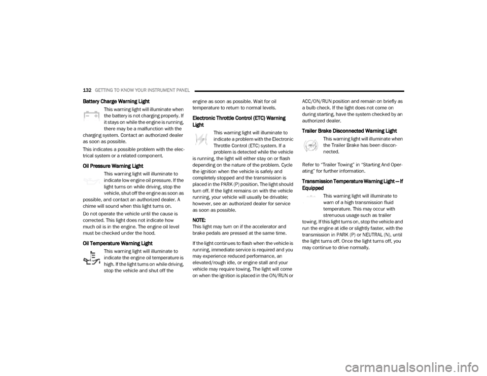
Battery Charge Warning Light
This warning light will illuminate when
the battery is not charging properly. If
it stays on while the engine is running,
there may be a malfunction with the
charging system. Contact an authorized dealer
as soon as possible.
This indicates a possible problem with the elec -
trical system or a related component.
Oil Pressure Warning Light
This warning light will illuminate to
indicate low engine oil pressure. If the
light turns on while driving, stop the
vehicle, shut off the engine as soon as
possible, and contact an authorized dealer. A
chime will sound when this light turns on.
Do not operate the vehicle until the cause is
corrected. This light does not indicate how
much oil is in the engine. The engine oil level
must be checked under the hood.
Oil Temperature Warning Light
This warning light will illuminate to
indicate the engine oil temperature is
high. If the light turns on while driving,
stop the vehicle and shut off the engine as soon as possible. Wait for oil
temperature to return to normal levels.
Electronic Throttle Control (ETC) Warning
Light
This warning light will illuminate to
indicate a problem with the Electronic
Throttle Control (ETC) system. If a
problem is detected while the vehicle
is running, the light will either stay on or flash
depending on the nature of the problem. Cycle
the ignition when the vehicle is safely and
completely stopped and the transmission is
placed in the PARK (P) position. The light should
turn off. If the light remains on with the vehicle
running, your vehicle will usually be drivable;
however, see an authorized dealer for service
as soon as possible.
NOTE:
This light may turn on if the accelerator and
brake pedals are pressed at the same time.
If the light continues to flash when the vehicle is
running, immediate service is required and you
may experience reduced performance, an
elevated/rough idle, or engine stall and your
vehicle may require towing. The light will come
on when the ignition is placed in the ON/RUN or ACC/ON/RUN position and remain on briefly as
a bulb check. If the light does not come on
during starting, have the system checked by an
authorized dealer.Trailer Brake Disconnected Warning Light
This warning light will illuminate when
the Trailer Brake has been discon
-
nected.
Refer to “Trailer Towing” in “Starting And Oper -
ating” for further information.
Transmission Temperature Warning Light — If
Equipped
This warning light will illuminate to
warn of a high transmission fluid
temperature. This may occur with
strenuous usage such as trailer
towing. If this light turns on, stop the vehicle and
run the engine at idle or slightly faster, with the
transmission in PARK (P) or NEUTRAL (N), until
the light turns off. Once the light turns off, you
may continue to drive normally.
20_DJD2_OM_EN_USC_t.book Page 132