Limit Ram 2500 2020 User Guide
[x] Cancel search | Manufacturer: RAM, Model Year: 2020, Model line: 2500, Model: Ram 2500 2020Pages: 553, PDF Size: 21.99 MB
Page 129 of 553

GETTING TO KNOW YOUR INSTRUMENT PANEL127
displayed. on pickup applications, and
approximately 7 gallons (26 Liters) are
required on chassis-cab applications.
Speed Limited to 5 MPH in XXX mi Refill DEF
— This message will continuously display if
the “DEF Low Refill Soon” message is
ignored, and the frequency of occurrence of
the chime will increase unless up to 2 gallons
(7.5 Liters) of DEF is added to the tank.
5 MPH Max Speed on Restart, Long Idle or
Refuel Refill DEF — This message will contin -
uously display when the counter reaches
zero, and will be accompanied by a periodic
chime.
The vehicle will only be capable of a
maximum speed of 5 MPH upon the first of
the following conditions to occur:
If the vehicle is shutoff and restarted.
If the vehicle is idled for an extended
period of time, approximately one hour or
greater.
If the system detects that the level of fuel in the tank has increased.
Add a minimum of 2 gallons (7.5 Liters) of DEF
to the tank in order to avoid vehicle operation
at a maximum speed of 5 MPH (8 km/H).
NOTE:
A minimum of 2 gallons (7.5 Liters) may be
required to restore normal vehicle operation.
Although the vehicle will start normally and can
be placed in gear after this message has been
initially displayed, extreme caution should be
utilized since the vehicle will only be capable of
maneuvering at a maximum speed of 5 MPH
(8 km/H).
Diesel Exhaust Fluid (DEF) Fault Warning
Messages
There are five different messages which are
displayed if the vehicle detects that the DEF
system has been filled with a fluid other than
DEF, has experienced component failures, or
when tampering has been detected. The vehicle
may be limited to a maximum speed of 5 MPH
(8 km/H) if the DEF system is not serviced
within less than 200 miles (322 km) of the fault
being detected.
When the DEF system needs to be serviced the
following warnings will display:
Service DEF System See Dealer — This
message will display when the fault is initially
detected, each time the vehicle is started,
and periodically during driving. The message
will be accompanied by a single chime. We
recommend you drive to your nearest autho -
rized dealer and have your vehicle serviced
as soon as possible.
5 MPH Max Speed in 150 mi Service DEF
System See Dealer — This message will
display if the DEF system has not been
serviced after the “Service DEF System – See
Dealer” message is displayed. This message
will continuously display until the mileage
counter reaches zero, and will be accompa -
nied by a periodic chime. The message will
continue to countdown until it reaches zero
unless the vehicle is serviced. We recom -
mend you drive to your nearest authorized
dealer and have your vehicle serviced imme -
diately.
NOTE:
Under some circumstances this mileage
counter may start with a value of less than
150 miles (241 km). For example, if recurring
faults are detected in a time interval of less
than 40 hours, the counter may restart at the
3
20_DJD2_OM_EN_USC_t.book Page 127
Page 133 of 553
GETTING TO KNOW YOUR INSTRUMENT PANEL131
the brake fluid level in the master cylinder has
dropped below a specified level.
The light will remain on until the cause is
corrected.
NOTE:
The light may flash momentarily during sharp
cornering maneuvers, which change fluid level
conditions. The vehicle should have service
performed, and the brake fluid level checked.
If brake failure is indicated, immediate repair is
necessary.
Vehicles equipped with the Anti-Lock Brake
System (ABS) are also equipped with Electronic
Brake Force Distribution (EBD). In the event of
an EBD failure, the Brake Warning Light will turn
on along with the ABS Light. Immediate repair to
the ABS system is required. Operation of the Brake Warning Light can be
checked by turning the ignition switch from the
OFF position to the ON/RUN position. The light
should illuminate for approximately two
seconds. The light should then turn off unless
the parking brake is applied or a brake fault is
detected. If the light does not illuminate, have
the light inspected by an authorized dealer.
The light also will turn on when the parking
brake is applied with the ignition switch in the
ON/RUN position.
NOTE:
This light shows only that the parking brake is
applied. It does not show the degree of brake
application.
Hood Open Warning Light
This warning light will illuminate when
the hood is ajar/open and not fully
closed.
NOTE:
If the vehicle is moving, there will also be a
single chime.
Vehicle Security Warning Light — If Equipped
This light will flash at a fast rate for
approximately 15 seconds when the
vehicle security alarm is arming, and
then will flash slowly until the vehicle
is disarmed.
Engine Coolant Temperature Warning Light
This warning light warns of an over -
heated engine condition. If the engine
coolant temperature is too high, this
indicator will illuminate and a single
chime will sound. If the temperature reaches
the upper limit, a continuous chime will sound
for four minutes or until the engine is able to
cool; whichever comes first.
If the light turns on while driving, safely pull over
and stop the vehicle. If the Air Conditioning
(A/C) system is on, turn it off. Also, shift the
transmission into NEUTRAL and idle the vehicle.
If the temperature reading does not return to
normal, turn the engine off immediately and call
for service.
Refer to “If Your Engine Overheats” in “In Case
Of Emergency” for further information.
WARNING!
Driving a vehicle with the red brake light on is
dangerous. Part of the brake system may
have failed. It will take longer to stop the
vehicle. You could have a collision. Have the
vehicle checked immediately.
3
20_DJD2_OM_EN_USC_t.book Page 131
Page 139 of 553
GETTING TO KNOW YOUR INSTRUMENT PANEL137
Service Forward Collision Warning (FCW)
Light — If Equipped
This warning light will illuminate to
indicate a fault in the Forward Colli-
sion Warning System. Contact an
authorized dealer for service.
Refer to "Forward Collision Warning (FCW)" in
"Safety" for further information.
Service 4WD Warning Light — If Equipped
This warning light will illuminate to
signal a fault with the 4WD system. If
the light stays on or comes on during
driving, it means that the 4WD system
is not functioning properly and that service is
required. We recommend you drive to the
nearest service center and have the vehicle
serviced immediately.
Speed Control Fault Warning Light
This warning light will illuminate to
indicate the Speed Control System is
not functioning properly and service is
required. Contact an authorized
dealer.
Sway Bar Fault Warning Light
This light will illuminate when there is
a fault in the sway bar disconnect
system.
Refer to “Stabilizer/Sway Bar System — Power
Wagon Only” in “Starting And Operating” for
further information.
Yellow Indicator Lights
Forward Collision Warning Off Indicator Light
— If Equipped
This indicator light illuminates to indi -
cate that Forward Collision Warning is
off.
Refer to “Auxiliary Driving Systems” in “Safety”
for further information.
Air Suspension Payload Protection Indicator
Light — If Equipped
This indicator light will illuminate to
indicate that the maximum payload
may have been exceeded or load
leveling cannot be achieved at its
current ride height. Protection Mode will auto -
matically be selected in order to “protect” the air suspension system, air suspension adjust
-
ment is limited due to payload.
TOW/HAUL Indicator Light
This indicator light will illuminate
when TOW/HAUL mode is selected.
Refer to “Trailer Towing” in “Starting
And Operating” for further informa -
tion.
Cargo Light — If Equipped
This indicator light will illuminate
when the cargo light is activated by
pushing the cargo light button on the
headlight switch.
Cold Ambient Derate Mode Indicator Light —
If Equipped
This indicator light will illuminate
when a derate (engine power reduc -
tion) is activated for protection of the
turbocharger in cold ambient
temperatures.
For further information, refer to “Instrument
Cluster Display” in “Getting To Know Your
Instrument Panel”.
3
20_DJD2_OM_EN_USC_t.book Page 137
Page 148 of 553
146SAFETY
(Continued)
Electronic Brake Force Distribution (EBD)
This function manages the distribution of the
braking torque between the front and rear axles
by limiting braking pressure to the rear axle.
This is done to prevent overslip of the rear
wheels to avoid vehicle instability, and to
prevent the rear axle from entering Anti-Lock
Brake System (ABS) before the front axle.
Electronic Stability Control (ESC)
This system enhances directional control and
stability of the vehicle under various driving
conditions. Electronic Stability Control (ESC)
corrects for oversteering or understeering of the
vehicle by applying the brake of the appropriate
wheel(s) to assist in counteracting the oversteer
or understeer condition. Engine power may also
be reduced to help the vehicle maintain the
desired path.
ESC uses sensors in the vehicle to determine
the vehicle path intended by the driver and
compares it to the actual path of the vehicle.
When the actual path does not match the
intended path, ESC applies the brake of the
appropriate wheel to assist in counteracting the
oversteer or understeer condition.
Oversteer — when the vehicle is turning more
than appropriate for the steering wheel posi-
tion.
Understeer — when the vehicle is turning less
than appropriate for the steering wheel posi -
tion.
The “ESC Activation/Malfunction Indicator
Light” located in the instrument cluster will start
to flash as soon as the ESC system becomes
active. The “ESC Activation/Malfunction Indi -
cator Light” also flashes when the TCS is active.
If the “ESC Activation/Malfunction Indicator
Light” begins to flash during acceleration, ease
up on the accelerator and apply as little throttle
as possible. Be sure to adapt your speed and
driving to the prevailing road conditions.
WARNING!
Electronic Stability Control (ESC) cannot
prevent the natural laws of physics from
acting on the vehicle, nor can it increase
the traction afforded by prevailing road
conditions. ESC cannot prevent accidents,
including those resulting from excessive
speed in turns, driving on very slippery
surfaces, or hydroplaning. ESC also cannot
prevent accidents resulting from loss of
vehicle control due to inappropriate driver
input for the conditions. Only a safe, atten -
tive, and skillful driver can prevent acci -
dents. The capabilities of an ESC equipped
vehicle must never be exploited in a reck -
less or dangerous manner which could
jeopardize the user’s safety or the safety of
others.
20_DJD2_OM_EN_USC_t.book Page 146
Page 149 of 553
SAFETY147
ESC Operating Modes
NOTE:
Depending upon model and mode of operation,
the ESC system may have multiple operating
modes. ESC On
This is the normal operating mode for the ESC.
Whenever the vehicle is started, the ESC system
will be in this mode. This mode should be used
for most driving conditions. Alternate ESC
modes should only be used for specific reasons
as noted in the following paragraphs.
Partial Off
The “Partial Off” mode is intended for times
when a more spirited driving experience is
desired. This mode may modify TCS and ESC
thresholds for activation, which allows for more
wheel spin than normally allowed. This mode
may be useful if the vehicle becomes stuck.
To enter the “Partial Off” mode, momentarily
push the “ESC OFF” switch and the “ESC OFF
Indicator Light” will illuminate. To turn the ESC
on again, momentarily push the “ESC OFF”
switch and the “ESC OFF Indicator Light” will
turn off.
NOTE:
For vehicles with multiple partial ESC modes, a
momentary button push will toggle the ESC
mode. Multiple momentary button pushes may
be required to return to ESC On.
Full Off — If Equipped
This mode is intended for off-highway or
off-road use only and should not be used on any
public roadways. In this mode, TCS and ESC
features are turned off. To enter the “Full Off”
mode, push and hold the “ESC OFF” switch for
five seconds while the vehicle is stopped with
the engine running. After five seconds, a chime
will sound, the “ESC OFF Indicator Light” will illu
-
minate, and the “ESC OFF” message will display
in the instrument cluster. To turn ESC on again,
momentarily push the “ESC OFF” switch.
Vehicle modifications, or failure to properly
maintain your vehicle, may change the
handling characteristics of your vehicle,
and may negatively affect the performance
of the ESC system. Changes to the steering
system, suspension, braking system, tire
type and size or wheel size may adversely
affect ESC performance. Improperly
inflated and unevenly worn tires may also
degrade ESC performance. Any vehicle
modification or poor vehicle maintenance
that reduces the effectiveness of the ESC
system can increase the risk of loss of
vehicle control, vehicle rollover, personal
injury and death.
WARNING! (Continued)WARNING!
When in “Partial Off” mode, the TCS func -
tionality of ESC, (except for the limited slip
feature described in the TCS section), has
been disabled and the “ESC Off Indicator
Light” will be illuminated. When in “Partial
Off” mode, the engine power reduction
feature of TCS is disabled, and the
enhanced vehicle stability offered by the
ESC system is reduced.
Trailer Sway Control (TSC) is disabled when
the ESC system is in the “Partial Off” mode.
4
20_DJD2_OM_EN_USC_t.book Page 147
Page 155 of 553
SAFETY153
Traction Control System (TCS)
This system monitors the amount of wheel spin
of each of the driven wheels. If wheel spin is
detected, the Traction Control System (TCS)
may apply brake pressure to the spinning
wheel(s) and/or reduce engine power to provide
enhanced acceleration and stability. A feature
of the TCS, Brake Limited Differential (BLD),
functions similar to a limited slip differential
and controls the wheel spin across a driven
axle. If one wheel on a driven axle is spinning
faster than the other, the system will apply the
brake of the spinning wheel. This will allow more
engine power to be applied to the wheel that is
not spinning. BLD may remain enabled even if
TCS and Electronic Stability Control (ESC) are in
a reduced mode.
Trailer Sway Control (TSC)
Trailer Sway Control (TSC) uses sensors in the
vehicle to recognize an excessively swaying
trailer and will take the appropriate actions to
attempt to stop the sway. TSC will become
active automatically once an excessively
swaying trailer is recognized. NOTE:
TSC cannot stop all trailers from swaying.
Always use caution when towing a trailer and
follow the trailer tongue weight recommenda
-
tions. Refer to “Trailer Towing” in “Starting And
Operating” for further information.
When TSC is functioning, the “ESC Activation/
Malfunction Indicator Light” will flash, the
engine power may be reduced and you may feel
the brakes being applied to individual wheels to
attempt to stop the trailer from swaying. TSC is
disabled when the ESC system is in the “Partial
Off” or “Full Off” modes.
AUXILIARY DRIVING SYSTEMS
Blind Spot Monitoring (BSM) — If Equipped
The Blind Spot Monitoring (BSM) system uses
two radar-based sensors, located inside the tail -
lights, to detect highway licensable vehicles
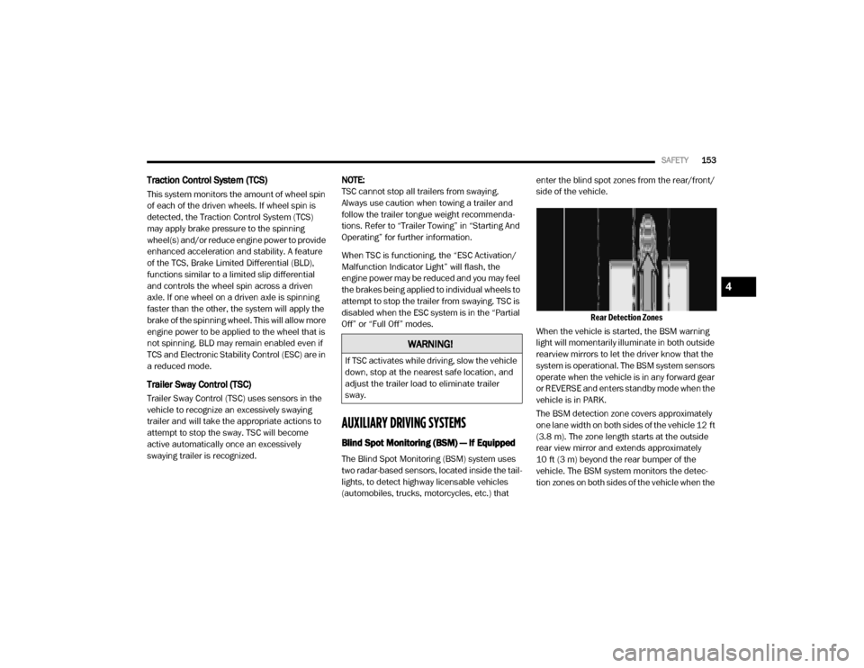
(automobiles, trucks, motorcycles, etc.) that enter the blind spot zones from the rear/front/
side of the vehicle.
Rear Detection Zones
When the vehicle is started, the BSM warning
light will momentarily illuminate in both outside
rearview mirrors to let the driver know that the
system is operational. The BSM system sensors
operate when the vehicle is in any forward gear
or REVERSE and enters standby mode when the
vehicle is in PARK.
The BSM detection zone covers approximately
one lane width on both sides of the vehicle 12 ft
(3.8 m). The zone length starts at the outside
rear view mirror and extends approximately
10 ft (3 m) beyond the rear bumper of the
vehicle. The BSM system monitors the detec -
tion zones on both sides of the vehicle when the
WARNING!
If TSC activates while driving, slow the vehicle
down, stop at the nearest safe location, and
adjust the trailer load to eliminate trailer
sway.
4
20_DJD2_OM_EN_USC_t.book Page 153
Page 161 of 553

SAFETY159
Trailer length will be identified and placed into
one of the following categories:
Trailer length up to 10 ft (3 m) — Blind spot
zone will be adjusted to 10 ft (3 m) .
Trailer length between 10 ft to 20 ft (3 m to
6 m) — Blind spot zone will be adjusted to
20 ft (6 m) .
Trailer length between 20 ft to 30 ft (6 m to
9 m) — Blind spot zone will be adjusted to
30 ft (9 m) .
Trailer length between 30 ft and 39.5 ft (9 m
to 12 m) — Blind spot zone will be adjusted to
MAX distance .
NOTE:
Trailer length is determined within +/- 3 ft (1 m)
of actual length. Trailers that are the same size
as the category limit, 10/20/30 ft (3/6/9 m),
could be subject to being placed in the category
above or below the correct one.
Trailer Merge Warning
Trailer Merge Warning is the extension of the
blind spot function to cover the length of the
trailer, plus a safety margin, to warn the driver
when there is a vehicle in the adjacent lane. The
driver is alerted by the illumination of the BSM warning light located in the outside mirror on
the side the other vehicle is detected. In addi
-
tion, an audible (chime) alert will be heard and
radio volume reduced. Refer to “Modes Of Oper -
ation” in this section for further information.
NOTE:
The Trailer Merge Alert system DOES NOT
alert the driver about rapidly approaching
vehicles that are outside the detection zones.
The Blind Spot Monitoring (BSM) system may
experience drop outs (blinking on and off) of
the side mirror warning indicator lamps when
a motorcycle or any small object remains at
the side of the vehicle for extended periods of
time (more than a couple of seconds).
Crowded areas such as parking lots, neigh -
borhoods, etc. May lead to an increased
amount of false alerts. This is normal opera -
tion.
General Information
The following regulatory statement applies to all
Radio Frequency (RF) devices equipped in this
vehicle:
This device complies with Part 15 of the FCC
Rules and with Innovation, Science and
Economic Development Canada license-exempt
RSS standard(s). Operation is subject to the
following two conditions:
1. This device may not cause harmful interfer -
ence, and
2. This device must accept any interference received, including interference that may
cause undesired operation.
WARNING!
The Blind Spot Monitoring system is only an
aid to help detect objects in the blind spot
zones. The BSM system is not designed to
detect pedestrians, bicyclists, or animals.
Even if your vehicle is equipped with the BSM
system, always check your vehicle’s mirrors,
glance over your shoulder, and use your turn
signal before changing lanes. Failure to do so
can result in serious injury or death.
4
20_DJD2_OM_EN_USC_t.book Page 159
Page 162 of 553
160SAFETY
Le présent appareil est conforme aux CNR
d`Innovation, Science and Economic Develop -
ment applicables aux appareils radio exempts
de licence. L'exploitation est autorisée aux deux
conditions suivantes:
1. l'appareil ne doit pas produire de brouil -
lage, et
2. l'utilisateur de l'appareil doit accepter tout brouillage radioélectrique subi, même si le
brouillage est susceptible d'en comprom -
ettre le fonctionnement.
La operación de este equipo está sujeta a las
siguientes dos condiciones:
1. es posible que este equipo o dispositivo no cause interferencia perjudicial y
2. este equipo o dispositivo debe aceptar cual -
quier interferencia, incluyendo la que
pueda causar su operación no deseada.
NOTE:
Changes or modifications not expressly
approved by the party responsible for compli -
ance could void the user’s authority to operate
the equipment.Forward Collision Warning (FCW) With
Mitigation — If Equipped
The Forward Collision Warning (FCW) system
provides the driver with audible, visual warnings
(within the instrument cluster display), and may
apply a haptic warning in the form of a brake
jerk, to warn the driver when it detects a poten -
tial frontal collision. The warnings are intended
to provide the driver with enough time to react,
avoid or mitigate the potential collision.
NOTE:
FCW monitors the information from the forward
looking sensors as well as Electronic Brake
Controller (EBC), to calculate the probability of a
forward collision. When the system determines
that a forward collision is probable, the driver
will be provided with audible and visual warn-
ings as well as a possible haptic warning in the
form of a brake jerk.
If the driver does not take action based upon
these progressive warnings, then the system
will provide a limited level of active braking to
help slow the vehicle and mitigate the potential
forward collision. If the driver reacts to the warn -
ings by braking and the system determines that
the driver intends to avoid the collision by
braking but has not applied sufficient brake force, the system will compensate and provide
additional brake force as required. When towing
a trailer, the system will also respond to activate
the trailer brakes (if equipped).
If a FCW with Mitigation event begins at a speed
below 32 mph (52 km/h), the system may
provide the maximum braking possible to miti
-
gate the potential forward collision. If the
Forward Collision Warning with Mitigation event
stops the vehicle completely, the system will
hold the vehicle at standstill for two seconds
and then release the brakes.
FCW Message
20_DJD2_OM_EN_USC_t.book Page 160
Page 163 of 553
SAFETY161
When the system determines a collision with
the vehicle in front of you is no longer probable,
the warning message will be deactivated.
NOTE:
The minimum speed for FCW activation is
3 mph (5 km/h).
The FCW alerts may be triggered on objects
other than vehicles such as guard rails or
sign posts based on the course prediction.
This is expected and is a part of normal FCW
activation and functionality.
It is unsafe to test the FCW system. To
prevent such misuse of the system, after four
Active Braking events within a key cycle, the
Active Braking portion of FCW will be deacti -
vated until the next key cycle.
The FCW system is intended for on-road use
only. If the vehicle is taken off-road, the FCW
system should be deactivated to prevent
unnecessary warnings to the surroundings.
FCW may not react to irrelevant objects such
as overhead objects, ground reflections,
objects not in the path of the vehicle,
stationary objects that are far away, oncoming traffic, or leading vehicles with the
same or higher rate of speed.
“FCW will be disabled like ACC, with the
unavailable screens.
During a FCW event when towing a trailer,
your Electronic Brake system will respond, to
activate the trailer brakes (if equipped).
Turning FCW On or Off
The FCW button is located in the Uconnect
display in the control settings. Refer to “Ucon
-
nect Settings” in “Multimedia” in the Owner's
Manual for further information.
To turn the FCW system on, press the forward
collision button once.
To turn the FCW system off, press the forward
collision button once.
NOTE:
When the FCW is “on”, this allows the system
to warn the driver of a possible collision with
the vehicle in front.
When the FCW is “off” prevents the system
from warning the driver of a possible collision
with the vehicle in front. If the FCW is set to
“off”, “FCW OFF" will be displayed in the
instrument cluster display.
When FCW status is set to “Only Warning”
prevents the system from providing limited
active braking, or additional brake support if
the driver is not braking adequately in the
event of a potential frontal collision.
When FCW status is set to “Warning and
Braking” this allows the system to warn the
driver of a possible collision with the vehicle
in front using audible/visual warnings and it
applies autonomous braking.
The FCW system state is defaulted to “Full
On” from one ignition cycle to the next. If the
system is turned off, it will reset to “Full On”
when the vehicle is restarted.
WARNING!
Forward Collision Warning (FCW) is not
intended to avoid a collision on its own, nor
can FCW detect every type of potential
collision. The driver has the responsibility to
avoid a collision by controlling the vehicle via
braking and steering. Failure to follow this
warning could lead to serious injury or death.
4
20_DJD2_OM_EN_USC_t.book Page 161
Page 164 of 553

162SAFETY
FCW Braking Status And Sensitivity
The FCW sensitivity and Active Braking status
are programmable through the Uconnect
System. Refer to “Uconnect Settings” in “Multi-
media” for further information.
Far
When the sensitivity of FCW is set to the
“Far” setting and the system status is
“Warning and Braking”, this allows the
system to warn the driver of a possible
more distant collisions with the vehicle in
front using audible/visual warnings.
More cautious drivers that do not mind frequent warnings may prefer this
setting.
Medium
When the sensitivity of FCW is set to the “Medium” setting and the system status
is “Warning and Braking”, this allows the
system to warn the driver of a possible
collision with the vehicle in front using
audible/visual warnings.
Near
When the sensitivity of FCW is set to the “Near” setting and the system status is “Warning and Braking”, this allows the
system to warn the driver of a possible
closer collisions with the vehicle in front
using audible/visual warnings.
This setting provides less reaction time
than the “Far” and “Medium” settings,
which allows for a more dynamic driving
experience.
More dynamic or aggressive drivers that want to avoid frequent warnings may
prefer this setting.
FCW Limited Warning
If the instrument cluster displays “ACC/FCW
Limited Functionality” or “ACC/FCW Limited
Functionality Clean Front Windshield” momen -
tarily, there may be a condition that limits FCW
functionality. Although the vehicle is still driv -
able under normal conditions, the active
braking may not be fully available. Once the
condition that limited the system performance
is no longer present, the system will return to its
full performance state. If the problem persists,
see an authorized dealer.
Service FCW Warning
If the system turns off, and the instrument
cluster displays:
ACC/FCW Unavailable Service Required
Cruise/FCW Unavailable Service Required
This indicates there is an internal system fault.
Although the vehicle is still drivable under
normal conditions, have the system checked by
an authorized dealer.
General Information
The following regulatory statement applies to all
Radio Frequency (RF) devices equipped in this
vehicle:
This device complies with Part 15 of the FCC
Rules and with Innovation, Science and
Economic Development Canada license-exempt
RSS standard(s). Operation is subject to the
following two conditions:
1. This device may not cause harmful interfer -
ence, and
2. This device must accept any interference received, including interference that may
cause undesired operation.
20_DJD2_OM_EN_USC_t.book Page 162