brake sensor Ram 2500 2020 Owner's Manual
[x] Cancel search | Manufacturer: RAM, Model Year: 2020, Model line: 2500, Model: Ram 2500 2020Pages: 553, PDF Size: 21.99 MB
Page 138 of 553
136GETTING TO KNOW YOUR INSTRUMENT PANEL
tire causes the tire to overheat and can lead to
tire failure. Under-inflation also reduces fuel
efficiency and tire tread life, and may affect the
vehicle’s handling and stopping ability.
Please note that the TPMS is not a substitute for
proper tire maintenance, and it is the driver’s
responsibility to maintain correct tire pressure,
even if under-inflation has not reached the level
to trigger illumination of the TPMS low tire pres-
sure telltale.
Your vehicle has also been equipped with a
TPMS malfunction indicator to indicate when
the system is not operating properly. The TPMS
malfunction indicator is combined with the low
tire pressure telltale. When the system detects
a malfunction, the telltale will flash for approxi -
mately one minute and then remain continu -
ously illuminated. This sequence will continue
upon subsequent vehicle start-ups as long as
the malfunction exists. When the malfunction
indicator is illuminated, the system may not be
able to detect or signal low tire pressure as
intended. TPMS malfunctions may occur for a
variety of reasons, including the installation of
replacement or alternate tires or wheels on the
vehicle that prevent the TPMS from functioning
properly. Always check the TPMS malfunction
telltale after replacing one or more tires or wheels on your vehicle to ensure that the
replacement or alternate tires and wheels allow
the TPMS to continue to function properly.
Anti-Lock Brake (ABS) Warning Light
This warning light monitors the
Anti-Lock Brake System (ABS). The
light will turn on when the ignition is
placed in the ON/RUN or ACC/ON/RUN position
and may stay on for as long as four seconds.
If the ABS light remains on or turns on while
driving, then the Anti-Lock portion of the brake
system is not functioning and service is
required as soon as possible. However, the
conventional brake system will continue to
operate normally, assuming the Brake Warning
Light is not also on.
If the ABS light does not turn on when the igni
-
tion is placed in the ON/RUN or ACC/ON/RUN
position, have the brake system inspected by an
authorized dealer.
Rear Axle Locker Fault Indicator Light — If
Equipped
This warning light will illuminate to
indicate when a rear axle locker fault
has been detected.
Refer to “Axle Locker System — Power
Wagon Models Only (If Equipped)” in “Starting
And Operating” for further information.
CAUTION!
The TPMS has been optimized for the original
equipment tires and wheels. TPMS pressures
and warning have been established for the
tire size equipped on your vehicle.
Undesirable system operation or sensor
damage may result when using replacement
equipment that is not of the same size, type,
and/or style. Aftermarket wheels can cause
sensor damage. Using aftermarket tire
sealants may cause the Tire Pressure
Monitoring System (TPMS) sensor to become
inoperable. After using an aftermarket tire
sealant it is recommended that you take your
vehicle to an authorized dealer to have your
sensor function checked.
20_DJD2_OM_EN_USC_t.book Page 136
Page 148 of 553
146SAFETY
(Continued)
Electronic Brake Force Distribution (EBD)
This function manages the distribution of the
braking torque between the front and rear axles
by limiting braking pressure to the rear axle.
This is done to prevent overslip of the rear
wheels to avoid vehicle instability, and to
prevent the rear axle from entering Anti-Lock
Brake System (ABS) before the front axle.
Electronic Stability Control (ESC)
This system enhances directional control and
stability of the vehicle under various driving
conditions. Electronic Stability Control (ESC)
corrects for oversteering or understeering of the
vehicle by applying the brake of the appropriate
wheel(s) to assist in counteracting the oversteer
or understeer condition. Engine power may also
be reduced to help the vehicle maintain the
desired path.
ESC uses sensors in the vehicle to determine
the vehicle path intended by the driver and
compares it to the actual path of the vehicle.
When the actual path does not match the
intended path, ESC applies the brake of the
appropriate wheel to assist in counteracting the
oversteer or understeer condition.
Oversteer — when the vehicle is turning more
than appropriate for the steering wheel posi-
tion.
Understeer — when the vehicle is turning less
than appropriate for the steering wheel posi -
tion.
The “ESC Activation/Malfunction Indicator
Light” located in the instrument cluster will start
to flash as soon as the ESC system becomes
active. The “ESC Activation/Malfunction Indi -
cator Light” also flashes when the TCS is active.
If the “ESC Activation/Malfunction Indicator
Light” begins to flash during acceleration, ease
up on the accelerator and apply as little throttle
as possible. Be sure to adapt your speed and
driving to the prevailing road conditions.
WARNING!
Electronic Stability Control (ESC) cannot
prevent the natural laws of physics from
acting on the vehicle, nor can it increase
the traction afforded by prevailing road
conditions. ESC cannot prevent accidents,
including those resulting from excessive
speed in turns, driving on very slippery
surfaces, or hydroplaning. ESC also cannot
prevent accidents resulting from loss of
vehicle control due to inappropriate driver
input for the conditions. Only a safe, atten -
tive, and skillful driver can prevent acci -
dents. The capabilities of an ESC equipped
vehicle must never be exploited in a reck -
less or dangerous manner which could
jeopardize the user’s safety or the safety of
others.
20_DJD2_OM_EN_USC_t.book Page 146
Page 155 of 553
SAFETY153
Traction Control System (TCS)
This system monitors the amount of wheel spin
of each of the driven wheels. If wheel spin is
detected, the Traction Control System (TCS)
may apply brake pressure to the spinning
wheel(s) and/or reduce engine power to provide
enhanced acceleration and stability. A feature
of the TCS, Brake Limited Differential (BLD),
functions similar to a limited slip differential
and controls the wheel spin across a driven
axle. If one wheel on a driven axle is spinning
faster than the other, the system will apply the
brake of the spinning wheel. This will allow more
engine power to be applied to the wheel that is
not spinning. BLD may remain enabled even if
TCS and Electronic Stability Control (ESC) are in
a reduced mode.
Trailer Sway Control (TSC)
Trailer Sway Control (TSC) uses sensors in the
vehicle to recognize an excessively swaying
trailer and will take the appropriate actions to
attempt to stop the sway. TSC will become
active automatically once an excessively
swaying trailer is recognized. NOTE:
TSC cannot stop all trailers from swaying.
Always use caution when towing a trailer and
follow the trailer tongue weight recommenda
-
tions. Refer to “Trailer Towing” in “Starting And
Operating” for further information.
When TSC is functioning, the “ESC Activation/
Malfunction Indicator Light” will flash, the
engine power may be reduced and you may feel
the brakes being applied to individual wheels to
attempt to stop the trailer from swaying. TSC is
disabled when the ESC system is in the “Partial
Off” or “Full Off” modes.
AUXILIARY DRIVING SYSTEMS
Blind Spot Monitoring (BSM) — If Equipped
The Blind Spot Monitoring (BSM) system uses
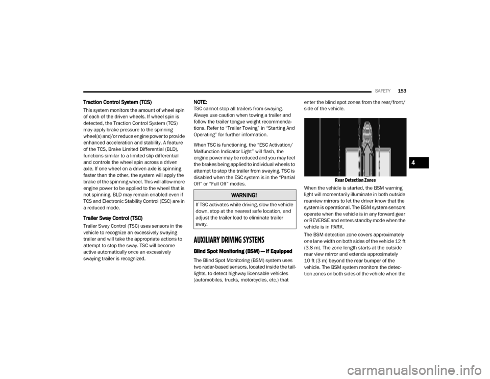
two radar-based sensors, located inside the tail -
lights, to detect highway licensable vehicles
(automobiles, trucks, motorcycles, etc.) that enter the blind spot zones from the rear/front/
side of the vehicle.
Rear Detection Zones
When the vehicle is started, the BSM warning
light will momentarily illuminate in both outside
rearview mirrors to let the driver know that the
system is operational. The BSM system sensors
operate when the vehicle is in any forward gear
or REVERSE and enters standby mode when the
vehicle is in PARK.
The BSM detection zone covers approximately
one lane width on both sides of the vehicle 12 ft
(3.8 m). The zone length starts at the outside
rear view mirror and extends approximately
10 ft (3 m) beyond the rear bumper of the
vehicle. The BSM system monitors the detec -
tion zones on both sides of the vehicle when the
WARNING!
If TSC activates while driving, slow the vehicle
down, stop at the nearest safe location, and
adjust the trailer load to eliminate trailer
sway.
4
20_DJD2_OM_EN_USC_t.book Page 153
Page 162 of 553
160SAFETY
Le présent appareil est conforme aux CNR
d`Innovation, Science and Economic Develop -
ment applicables aux appareils radio exempts
de licence. L'exploitation est autorisée aux deux
conditions suivantes:
1. l'appareil ne doit pas produire de brouil -
lage, et
2. l'utilisateur de l'appareil doit accepter tout brouillage radioélectrique subi, même si le
brouillage est susceptible d'en comprom -
ettre le fonctionnement.
La operación de este equipo está sujeta a las
siguientes dos condiciones:
1. es posible que este equipo o dispositivo no cause interferencia perjudicial y
2. este equipo o dispositivo debe aceptar cual -
quier interferencia, incluyendo la que
pueda causar su operación no deseada.
NOTE:
Changes or modifications not expressly
approved by the party responsible for compli -
ance could void the user’s authority to operate
the equipment.Forward Collision Warning (FCW) With
Mitigation — If Equipped
The Forward Collision Warning (FCW) system
provides the driver with audible, visual warnings
(within the instrument cluster display), and may
apply a haptic warning in the form of a brake
jerk, to warn the driver when it detects a poten -
tial frontal collision. The warnings are intended
to provide the driver with enough time to react,
avoid or mitigate the potential collision.
NOTE:
FCW monitors the information from the forward
looking sensors as well as Electronic Brake
Controller (EBC), to calculate the probability of a
forward collision. When the system determines
that a forward collision is probable, the driver
will be provided with audible and visual warn-
ings as well as a possible haptic warning in the
form of a brake jerk.
If the driver does not take action based upon
these progressive warnings, then the system
will provide a limited level of active braking to
help slow the vehicle and mitigate the potential
forward collision. If the driver reacts to the warn -
ings by braking and the system determines that
the driver intends to avoid the collision by
braking but has not applied sufficient brake force, the system will compensate and provide
additional brake force as required. When towing
a trailer, the system will also respond to activate
the trailer brakes (if equipped).
If a FCW with Mitigation event begins at a speed
below 32 mph (52 km/h), the system may
provide the maximum braking possible to miti
-
gate the potential forward collision. If the
Forward Collision Warning with Mitigation event
stops the vehicle completely, the system will
hold the vehicle at standstill for two seconds
and then release the brakes.
FCW Message
20_DJD2_OM_EN_USC_t.book Page 160
Page 277 of 553

STARTING AND OPERATING275
Metric Speed (km/h)
Pushing the SET (-) button once will result in
a 1 km/h decrease in set speed. Each subse -
quent tap of the button results in a decrease
of 1 km/h.
If the button is continually pushed, the set
speed will continue to decrease until the
button is released, then the new set speed
will be established.
To Accelerate For Passing
Press the accelerator as you would normally.
When the pedal is released, the vehicle will
return to the set speed.
Using Speed Control On Hills
The transmission may downshift on hills to
maintain the vehicle set speed.
NOTE:
The Speed Control system maintains speed up
and down hills. A slight speed change on
moderate hills is normal.
On steep hills, a greater speed loss or gain may
occur so it may be preferable to drive without
Speed Control.
To Resume Speed
To resume a previously set speed, push the RES
(+) button and release. Resume can be used at
any speed above 20 mph (32 km/h).
To Deactivate
A soft tap on the brake pedal, pushing the
CANCEL button, or normal brake pressure while
slowing the vehicle will deactivate the Speed
Control without erasing the set speed from
memory.
Pushing the on/off button, or placing the igni -
tion in the OFF position, erases the set speed
from memory. The following conditions will also deactivate the
Speed Control without erasing the set speed
from memory:
Vehicle parking brake is applied
Stability event occurs
Gear selector is moved out of DRIVE
Engine overspeed occurs
ADAPTIVE CRUISE CONTROL (ACC) — IF
EQUIPPED
Adaptive Cruise Control (ACC) increases the
driving convenience provided by cruise control
while traveling on highways and major road
-
ways. However, it is not a safety system and not
designed to prevent collisions. Speed Control
function performs differently. Please refer to
the proper section within this chapter.
ACC will allow you to keep cruise control
engaged in light to moderate traffic conditions
without the constant need to reset your cruise
control. ACC utilizes a radar sensor and a
forward facing camera designed to detect a
vehicle directly ahead of you.
WARNING!
Speed Control can be dangerous where the
system cannot maintain a constant speed.
Your vehicle could go too fast for the
conditions, and you could lose control and
have an accident. Do not use Speed Control
in heavy traffic or on roads that are winding,
icy, snow-covered or slippery.
5
20_DJD2_OM_EN_USC_t.book Page 275
Page 278 of 553
276STARTING AND OPERATING
(Continued)
(Continued)
NOTE:
If the sensor does not detect a vehicle ahead
of you, ACC will maintain a fixed set speed.
If the ACC sensor detects a vehicle ahead,
ACC will apply limited braking or accelerate
(not to exceed the original set speed) auto -
matically to maintain a preset following
distance, while matching the speed of the
vehicle ahead.
The Cruise Control system has two control
modes:
Adaptive Cruise Control mode for main -
taining an appropriate distance between
vehicles.
Normal (Fixed Speed) Cruise Control mode
for cruising at a constant preset speed. For
additional information, refer to “Normal
(Fixed Speed) Cruise Control Mode” in this
section.
NOTE:
Normal (Fixed Speed) Cruise Control will not
react to preceding vehicles. Always be aware of
the mode selected. You can change the mode by using the Cruise
Control buttons. The two control modes func
-
tion differently. Always confirm which mode is
selected.
WARNING!
Adaptive Cruise Control (ACC) is a conve -
nience system. It is not a substitute for
active driving involvement. It is always the
driver’s responsibility to be attentive of
road, traffic, and weather conditions,
vehicle speed, distance to the vehicle
ahead; and, most importantly, brake opera -
tion to ensure safe operation of the vehicle
under all road conditions. Your complete
attention is always required while driving to
maintain safe control of your vehicle.
Failure to follow these warnings can result
in a collision and death or serious personal
injury.
The ACC system:
Does not react to pedestrians,
oncoming vehicles, and stationary
objects (e.g., a stopped vehicle in a
traffic jam or a disabled vehicle).
Cannot take street, traffic, and weather conditions into account, and may be
limited upon adverse sight distance
conditions.
Does not always fully recognize complex driving conditions, which can
result in wrong or missing distance
warnings.
Will bring the vehicle to a complete stop while following a target vehicle and hold
the vehicle for approximately two
seconds in the stop position. At this
point, there will be an “ACC may cancel
soon” chime and warning to the driver.
When ACC is cancelled, the system will
release the brakes and the driver must
take over braking. The system can be
resumed when the target vehicle drives
off by releasing the brake and pushing
the resume button on the steering
wheel.
WARNING! (Continued)
20_DJD2_OM_EN_USC_t.book Page 276
Page 283 of 553

STARTING AND OPERATING281
Distance Setting 4 Bars (Longest)
Distance Setting 3 Bars (Long) Distance Setting 2 Bars (Medium)
Distance Setting 1 Bar (Short)
The system automatically defaults to the
longest distance setting. To decrease the
distance setting, push the Distance Button and
release. Each time the button is pushed, the
distance setting decreases by one bar. Once the
shortest setting is reached, if the button is pushed again it will reset to the default setting
(longest).
If there is no vehicle ahead, the vehicle will
maintain the set speed. If a slower moving
vehicle is detected in the same lane, the instru
-
ment cluster displays the ACC Set With Target
Indicator Light, and the system adjusts vehicle
speed automatically to maintain the distance
setting, regardless of the set speed.
The vehicle will then maintain the set distance
until:
The vehicle ahead accelerates to a speed
above the set speed.
The vehicle ahead moves out of your lane or
view of the sensor.
The distance setting is changed.
The system disengages. (Refer to “Activating
Adaptive Cruise Control (ACC)” in this
chapter.
The maximum braking applied by ACC is limited;
however, the driver can always apply the brakes
manually, if necessary.
5
20_DJD2_OM_EN_USC_t.book Page 281
Page 286 of 553
284STARTING AND OPERATING
malfunction or failure and require a sensor
realignment.
Do not attach or install any accessories near
the sensor, including transparent material or
aftermarket grilles. Doing so could cause an
ACC system failure or malfunction.
When the condition that deactivated the system
is no longer present, the system will return to
the “Adaptive Cruise Control Off” state and will
resume function by simply reactivating it.
NOTE:
If the “ACC/FCW Unavailable Wipe Front
Radar Sensor” message occurs frequently
(e.g. more than once on every trip) without
any snow, rain, mud, or other obstruction,
have the radar sensor realigned at your
authorized dealer.
Installing a snow plow, front-end protector,
an aftermarket grille or modifying the grille is
not recommended. Doing so may block the
sensor and inhibit ACC/FCW operation.
“Clean Front Windshield” Warning
The “ACC/FCW Limited Functionality Clean
Front Windshield” warning will display and also
a chime will indicate when conditions tempo -rarily limit system performance. This most often
occurs at times of poor visibility, such as in
snow or heavy rain and fog. The ACC system
may also become temporarily blinded due to
obstructions, such as mud, dirt, or ice on wind
-
shield, driving directly into the sun and fog on
the inside of glass. In these cases, the instru -
ment cluster display will show “ACC/FCW
Limited Functionality Clean Front Windshield”
and the system will have degraded perfor -
mance.
The “ACC/FCW Limited Functionality Clean
Front Windshield” message can sometimes be
displayed while driving in adverse weather
conditions. The ACC/FCW system will recover
after the vehicle has left these areas. Under
rare conditions, when the camera is not
tracking any vehicles or objects in its path this
warning may temporarily occur.
If weather conditions are not a factor, the driver
should examine the windshield and the camera
located on the back side of the inside rearview
mirror. They may require cleaning or removal of
an obstruction.
When the condition that created limited func -
tionality is no longer present, the system will
return to full functionality. NOTE:
If the “ACC/FCW Limited Functionality Clean
Front Windshield” message occurs frequently
(e.g. more than once on every trip) without any
snow, rain, mud, or other obstruction, have the
windshield and forward facing camera
inspected at your authorized dealer.
Service ACC/FCW Warning
If the system turns off, and the instrument
cluster displays “ACC/FCW Unavailable Service
Required” or “Cruise/FCW Unavailable Service
Required”, there may be an internal system
fault or a temporary malfunction that limits ACC
functionality. Although the vehicle is still driv
-
able under normal conditions, ACC will be
temporarily unavailable. If this occurs, try acti -
vating ACC again later, following an ignition
cycle. If the problem persists, see your autho -
rized dealer.
Precautions While Driving With ACC
In certain driving situations, ACC may have
detection issues. In these cases, ACC may
brake late or unexpectedly. The driver needs to
stay alert and may need to intervene.
20_DJD2_OM_EN_USC_t.book Page 284
Page 294 of 553
292STARTING AND OPERATING
Adjustable Chime Volume Settings
The rear chime volume settings are program -
mable through the Uconnect system. Refer to
“Uconnect Settings” in “Multimedia” for further
information.
The chime volume settings include low,
medium, and high. The factory default volume is
medium.
Enabling And Disabling ParkSense
ParkSense can be enabled and disabled with
the ParkSense switch.
When the gear selector is moved to
REVERSE and the system is disabled,
the instrument cluster display will
show the vehicle graphic with “Off”
over the arcs for as long as the vehicle is in
REVERSE.
NOTE:
The ParkSense system will automatically
disable when the system detects that a trailer
with trailer brakes has been connected to the
Integrated Trailer Brake Module. The instru -
ment cluster display will show an “Off” message over the arcs if the ParkSense system is off, or
a “Trailer” message if the system is on, for as
long as the vehicle is in REVERSE.
The ParkSense switch LED will be on when Park-
Sense is disabled or defective. The ParkSense
switch LED will be off when the system is
enabled.
If the ParkSense switch is pushed, and the
system is disabled or requires service, the Park-
Sense switch LED will blink momentarily, and
then the LED will be on.
Service The ParkSense Rear Park Assist
System
During vehicle start up, when the Rear Park
-
Sense System has detected a faulted condition,
the instrument cluster display will show the
"Rear ParkSense Unavailable Service Required"
or the "Rear ParkSense Unavailable Wipe
Sensors" message.
When the gear selector is moved into REVERSE,
a vehicle graphic will show in the instrument
cluster display, along with the display overlay
“Rear ParkSense Unavailable Wipe Sensors.” If
the system needs service, the display overlay
will read “Rear ParkSense Unavailable Service Required” Under this condition, ParkSense will
not operate.
If "Rear ParkSense Unavailable Wipe Sensors"
appears in the instrument cluster display make
sure the outer surface and the underside of the
rear fascia/bumper is clean and clear of snow,
ice, mud, dirt or other obstruction, and then
cycle the ignition. If the message continues to
appear, see an authorized dealer.
If "Rear ParkSense Unavailable Service
Required" appears in the instrument cluster
display, see an authorized dealer.
Cleaning The ParkSense System
Clean the ParkSense sensors with water, car
wash soap and a soft cloth. Do not use rough or
hard cloths. Do not scratch or poke the sensors.
Otherwise, you could damage the sensors.
ParkSense System Usage Precautions
NOTE:
Ensure that the rear bumper is free of snow,
ice, mud, dirt and debris to keep the Park
-
Sense system operating properly.
Jackhammers, large trucks, and other vibra -
tions could affect the performance of Park -
Sense.
20_DJD2_OM_EN_USC_t.book Page 292
Page 359 of 553
IN CASE OF EMERGENCY357
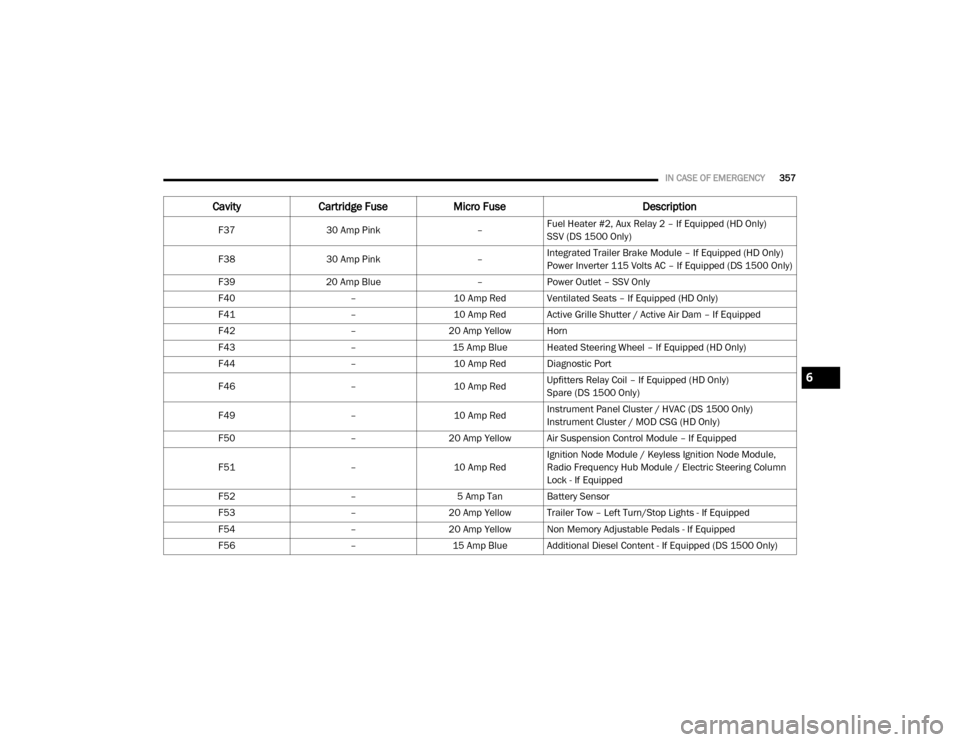
F3730 Amp Pink –Fuel Heater #2, Aux Relay 2 – If Equipped (HD Only)
SSV (DS 1500 Only)
F38 30 Amp Pink –Integrated Trailer Brake Module – If Equipped (HD Only)
Power Inverter 115 Volts AC – If Equipped (DS 1500 Only)
F39 20 Amp Blue –Power Outlet – SSV Only
F40 –10 Amp Red Ventilated Seats – If Equipped (HD Only)
F41 –10 Amp Red Active Grille Shutter / Active Air Dam – If Equipped
F42 –20 Amp Yellow Horn
F43 –15 Amp Blue Heated Steering Wheel – If Equipped (HD Only)
F44 –10 Amp Red Diagnostic Port
F46 –10 Amp RedUpfitters Relay Coil – If Equipped (HD Only)
Spare (DS 1500 Only)
F49 –10 Amp RedInstrument Panel Cluster / HVAC (DS 1500 Only)
Instrument Cluster / MOD CSG (HD Only)
F50 –20 Amp Yellow Air Suspension Control Module – If Equipped
F51 –10 Amp RedIgnition Node Module / Keyless Ignition Node Module,
Radio Frequency Hub Module / Electric Steering Column
Lock - If Equipped
F52 –5 Amp Tan Battery Sensor
F53 –20 Amp Yellow Trailer Tow – Left Turn/Stop Lights - If Equipped
F54 –20 Amp Yellow Non Memory Adjustable Pedals - If Equipped
F56 –15 Amp Blue Additional Diesel Content - If Equipped (DS 1500 Only)
CavityCartridge Fuse Micro Fuse Description
6
20_DJD2_OM_EN_USC_t.book Page 357