engine coolant Ram 2500 2020 Owner's Manual
[x] Cancel search | Manufacturer: RAM, Model Year: 2020, Model line: 2500, Model: Ram 2500 2020Pages: 553, PDF Size: 21.99 MB
Page 71 of 553

GETTING TO KNOW YOUR VEHICLE69
NOTE:
It is not necessary to move the temperature
settings for cold or hot vehicles. The system
automatically adjusts the temperature,
mode, and blower speed to provide comfort
as quickly as possible.
The temperature can be displayed in U.S. or
Metric units by selecting the U.S./Metric
customer-programmable feature. Refer to
the “Uconnect Settings” in “Multimedia” for
further information.
To provide you with maximum comfort in the
Automatic mode during cold start-ups, the
blower fan will remain on low until the engine
warms up. The blower will increase in speed
and transition into Auto mode.
Manual Operation Override
This system offers a full complement of manual
override features. The AUTO symbol in the front
ATC display will be turned off when the system
is being used in the manual mode.
Operating Tips
NOTE:
Refer to the chart at the end of this section for
suggested control settings for various weather
conditions.
Summer Operation
The engine cooling system must be protected
with a high-quality antifreeze coolant to provide
proper corrosion protection and to protect
against engine overheating. OAT coolant
(conforming to MS.90032) is recommended.
Winter Operation
To ensure the best possible heater and
defroster performance, make sure the engine
cooling system is functioning properly and the
proper amount, type, and concentration of
coolant is used. Use of the Air Recirculation
mode during Winter months is not recom -
mended, because it may cause window fogging.
Vacation/Storage
Before you store your vehicle, or keep it out of
service (i.e., vacation) for two weeks or more,
run the air conditioning system at idle for about
five minutes, in fresh air with the blower setting
on high. This will ensure adequate system lubri -cation to minimize the possibility of compressor
damage when the system is started again.
Window Fogging
Vehicle windows tend to fog on the inside in
mild, rainy, and/or humid weather. To clear the
windows, select Defrost or Mix mode and
increase the front blower speed. Do not use the
Recirculation mode without A/C for long
periods, as fogging may occur.
CAUTION!
Failure to follow these cautions can cause
damage to the heating elements:
Use care when washing the inside of the
rear window. Do not use abrasive window
cleaners on the interior surface of the
window. Use a soft cloth and a mild
washing solution, wiping parallel to the
heating elements. Labels can be peeled off
after soaking with warm water.
Do not use scrapers, sharp instruments, or
abrasive window cleaners on the interior
surface of the window.
Keep all objects a safe distance from the
window.
2
20_DJD2_OM_EN_USC_t.book Page 69
Page 111 of 553
GETTING TO KNOW YOUR INSTRUMENT PANEL109
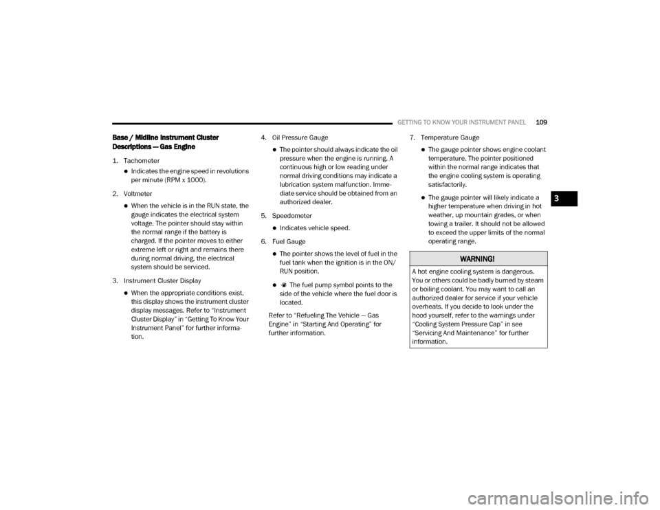
Base / Midline Instrument Cluster
Descriptions — Gas Engine
1. Tachometer
Indicates the engine speed in revolutions
per minute (RPM x 1000).
2. Voltmeter
When the vehicle is in the RUN state, the gauge indicates the electrical system
voltage. The pointer should stay within
the normal range if the battery is
charged. If the pointer moves to either
extreme left or right and remains there
during normal driving, the electrical
system should be serviced.
3. Instrument Cluster Display
When the appropriate conditions exist, this display shows the instrument cluster
display messages. Refer to “Instrument
Cluster Display” in “Getting To Know Your
Instrument Panel” for further informa -
tion. 4. Oil Pressure Gauge
The pointer should always indicate the oil
pressure when the engine is running. A
continuous high or low reading under
normal driving conditions may indicate a
lubrication system malfunction. Imme -
diate service should be obtained from an
authorized dealer.
5. Speedometer
Indicates vehicle speed.
6. Fuel Gauge
The pointer shows the level of fuel in the fuel tank when the ignition is in the ON/
RUN position.
The fuel pump symbol points to the
side of the vehicle where the fuel door is
located.
Refer to “Refueling The Vehicle — Gas
Engine” in “Starting And Operating” for
further information. 7. Temperature Gauge
The gauge pointer shows engine coolant
temperature. The pointer positioned
within the normal range indicates that
the engine cooling system is operating
satisfactorily.
The gauge pointer will likely indicate a higher temperature when driving in hot
weather, up mountain grades, or when
towing a trailer. It should not be allowed
to exceed the upper limits of the normal
operating range.
WARNING!
A hot engine cooling system is dangerous.
You or others could be badly burned by steam
or boiling coolant. You may want to call an
authorized dealer for service if your vehicle
overheats. If you decide to look under the
hood yourself, refer to the warnings under
“Cooling System Pressure Cap” in see
“Servicing And Maintenance” for further
information.
3
20_DJD2_OM_EN_USC_t.book Page 109
Page 114 of 553
112GETTING TO KNOW YOUR INSTRUMENT PANEL
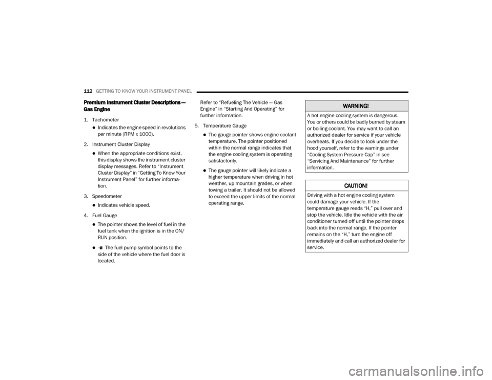
Premium Instrument Cluster Descriptions —
Gas Engine
1. Tachometer
Indicates the engine speed in revolutions
per minute (RPM x 1000).
2. Instrument Cluster Display
When the appropriate conditions exist, this display shows the instrument cluster
display messages. Refer to “Instrument
Cluster Display” in “Getting To Know Your
Instrument Panel” for further informa -
tion.
3. Speedometer
Indicates vehicle speed.
4. Fuel Gauge
The pointer shows the level of fuel in the fuel tank when the ignition is in the ON/
RUN position.
The fuel pump symbol points to the
side of the vehicle where the fuel door is
located. Refer to “Refueling The Vehicle — Gas
Engine” in “Starting And Operating” for
further information.
5. Temperature Gauge
The gauge pointer shows engine coolant temperature. The pointer positioned
within the normal range indicates that
the engine cooling system is operating
satisfactorily.
The gauge pointer will likely indicate a higher temperature when driving in hot
weather, up mountain grades, or when
towing a trailer. It should not be allowed
to exceed the upper limits of the normal
operating range.
WARNING!
A hot engine cooling system is dangerous.
You or others could be badly burned by steam
or boiling coolant. You may want to call an
authorized dealer for service if your vehicle
overheats. If you decide to look under the
hood yourself, refer to the warnings under
“Cooling System Pressure Cap” in see
“Servicing And Maintenance” for further
information.
CAUTION!
Driving with a hot engine cooling system
could damage your vehicle. If the
temperature gauge reads “H,” pull over and
stop the vehicle. Idle the vehicle with the air
conditioner turned off until the pointer drops
back into the normal range. If the pointer
remains on the “H,” turn the engine off
immediately and call an authorized dealer for
service.
20_DJD2_OM_EN_USC_t.book Page 112
Page 116 of 553
114GETTING TO KNOW YOUR INSTRUMENT PANEL
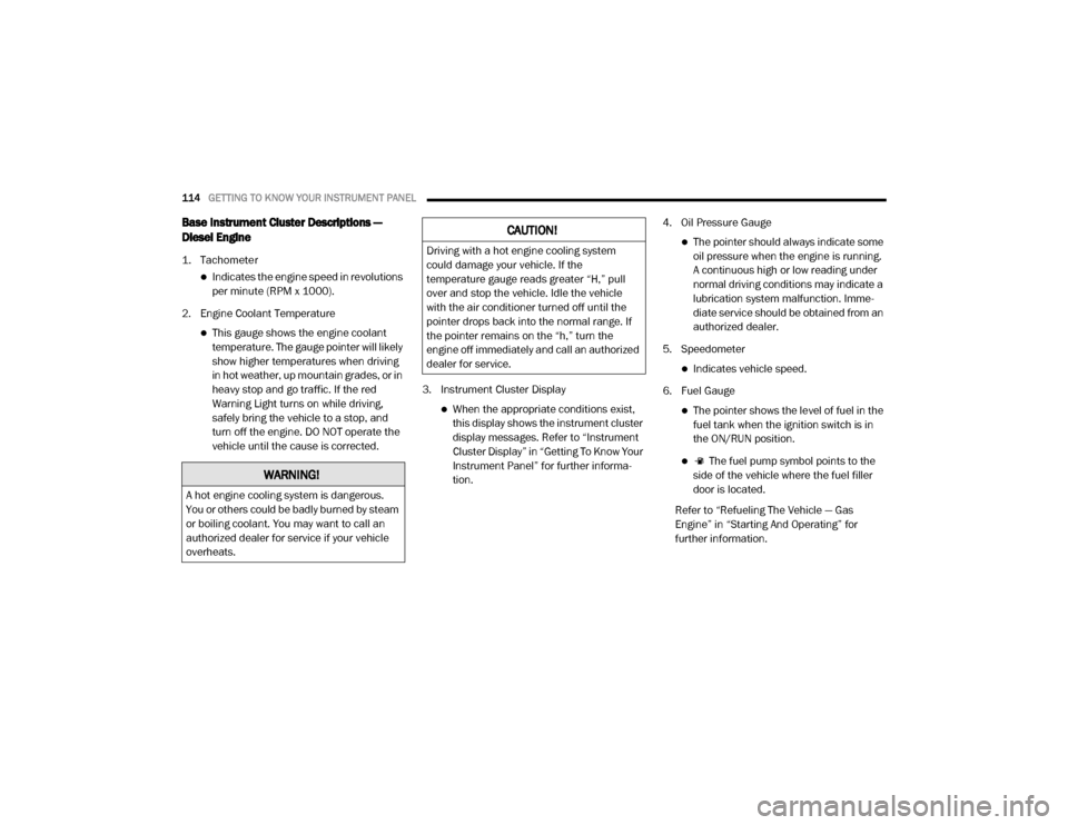
Base Instrument Cluster Descriptions —
Diesel Engine
1. Tachometer
Indicates the engine speed in revolutions
per minute (RPM x 1000).
2. Engine Coolant Temperature
This gauge shows the engine coolant temperature. The gauge pointer will likely
show higher temperatures when driving
in hot weather, up mountain grades, or in
heavy stop and go traffic. If the red
Warning Light turns on while driving,
safely bring the vehicle to a stop, and
turn off the engine. DO NOT operate the
vehicle until the cause is corrected. 3. Instrument Cluster Display
When the appropriate conditions exist,
this display shows the instrument cluster
display messages. Refer to “Instrument
Cluster Display” in “Getting To Know Your
Instrument Panel” for further informa -
tion. 4. Oil Pressure Gauge
The pointer should always indicate some
oil pressure when the engine is running.
A continuous high or low reading under
normal driving conditions may indicate a
lubrication system malfunction. Imme -
diate service should be obtained from an
authorized dealer.
5. Speedometer
Indicates vehicle speed.
6. Fuel Gauge
The pointer shows the level of fuel in the fuel tank when the ignition switch is in
the ON/RUN position.
The fuel pump symbol points to the
side of the vehicle where the fuel filler
door is located.
Refer to “Refueling The Vehicle — Gas
Engine” in “Starting And Operating” for
further information.
WARNING!
A hot engine cooling system is dangerous.
You or others could be badly burned by steam
or boiling coolant. You may want to call an
authorized dealer for service if your vehicle
overheats.
CAUTION!
Driving with a hot engine cooling system
could damage your vehicle. If the
temperature gauge reads greater “H,” pull
over and stop the vehicle. Idle the vehicle
with the air conditioner turned off until the
pointer drops back into the normal range. If
the pointer remains on the “h,” turn the
engine off immediately and call an authorized
dealer for service.
20_DJD2_OM_EN_USC_t.book Page 114
Page 122 of 553

120GETTING TO KNOW YOUR INSTRUMENT PANEL
Speedometer
Push and release the up or down arrow button
until the speedometer menu item is highlighted
in the instrument cluster display. Push and
release the right arrow button to cycle the
display between mph and km/h.
Vehicle Info
Push and release the up or down arrow button
until the Vehicle Info menu item is highlighted in
the instrument cluster display. Push and
release the right arrow button to enter the
submenus items of Vehicle Info. Follow the
directional prompts to access or reset any of the
following Vehicle Info submenu items:
Tire Pressure
Coolant Temperature
Transmission Temperature — If Equipped
Oil Temperature
Oil Pressure
Exhaust Brake — If Equipped
Turbo Boost — If Equipped
Oil Life
Fuel Filter Life — If Equipped
Battery Voltage
Gauge Summary
Engine Hours
Driver Assist — If Equipped
The Driver Assist menu displays the status of
the Adaptive Cruise Control (ACC) and Lane -
Sense systems.
Push and release the up or down arrow button
until the Driver Assist menu is displayed in the
instrument cluster display.
Adaptive Cruise Control (ACC) Feature
The instrument cluster display displays the
current ACC system settings. The information
displayed depends on ACC system status.
Push the Adaptive Cruise Control (ACC) on/off
button (located on the steering wheel) until one
of the following displays in the instrument
cluster display:
Adaptive Cruise Control Off
When ACC is deactivated, the display will read
“Adaptive Cruise Control Off.” Adaptive Cruise Control Ready
When ACC is activated but the vehicle speed
setting has not been selected, the display will
read “Adaptive Cruise Control Ready.”
Push the SET + or the SET- button (located on
the steering wheel) and the following will display
in the instrument cluster display:
ACC SET
When ACC is set, the set speed will display in
the instrument cluster.
The ACC screen may display once again if any
ACC activity occurs, which may include any of
the following:
Distance Setting Change
System Cancel
Driver Override
System Off
ACC Proximity Warning
ACC Unavailable Warning
For further information, refer to “Adaptive
Cruise Control (ACC) — If Equipped” in “Starting
And Operating.”
20_DJD2_OM_EN_USC_t.book Page 120
Page 126 of 553

124GETTING TO KNOW YOUR INSTRUMENT PANEL
Transmission Temperature
Oil Life
Exhaust Brake — If Equipped
Turbo Boost — If Equipped
Fuel Filter Life — If Equipped
Lower Right — If Equipped
None
Compass
Outside Temp
Time
Range To Empty
Average MPG
Current MPG
Trip A Distance
Trip B Distance
Trailer Trip
Trailer Brake
Oil Pressure (Default Setting)
Coolant Temperature
Oil Temperature
Battery Voltage
Transmission Temperature
Oil Life
Exhaust Brake — If Equipped
Turbo Boost — If Equipped
Fuel Filter Life — If Equipped
Restore Defaults
Cancel (Default Setting)
Right Arrow Button
Commercial Settings — If Equipped
Commercial Settings allows the driver to set
and recall additional features when the trans-
mission is in PARK (P).
Push and release the up and down button until
Commercial Settings displays in the instrument
cluster display.
Follow the prompts to enter the required PIN
and enter the Commercial Settings submenu. Commercial Settings allows you to access the
following features (if equipped):
Backup Alarm
ParkSense
Aux Switches
PIN Setup
NOTE:
If the vehicle’s PIN is forgotten or not known,
see an authorized dealer to have the PIN reset.
Diesel Messages And Warnings — 6.7L
Cummins Diesel Engine
Diesel Particulate Filter (DPF) Messages
The Cummins diesel engine meets all diesel
emissions standards, resulting in one of the
lowest emitting diesel engines ever produced.
To achieve these emissions standards, your
vehicle is equipped with a state-of-the-art
engine and exhaust system. These systems are
seamlessly integrated into your vehicle and
managed by the Powertrain Control Module
(PCM). The PCM manages engine combustion
to allow the exhaust system’s catalyst to trap
and burn Particulate Matter (PM) pollutants,
with no input or interaction on your part.
20_DJD2_OM_EN_USC_t.book Page 124
Page 128 of 553

126GETTING TO KNOW YOUR INSTRUMENT PANEL
Exhaust Filter Full — Power Reduced See
Dealer — This message indicates the PCM
has derated the engine to limit the likelihood
of permanent damage to the after-treatment
system. If this condition is not corrected and
a dealer service is not performed, extensive
exhaust after-treatment damage can occur.
To correct this condition it will be necessary
to have your vehicle serviced by your local
authorized dealer.
NOTE:
Failing to follow the oil change indicator,
changing your oil and resetting the oil change
indicator by 0 miles remaining will prevent the
diesel exhaust filter from performing it's
cleaning routine. This will shortly result in a
Malfunction Indicator Light (MIL) and reduced
engine power. Only an authorized dealer will be
able to correct this condition.Cold Ambient Derate Mode Messages
The vehicle will display messages when a
derate (engine power reduction) is activated to
protect the engine during start up in cold
ambient temperatures.
Engine Power Reduced During Warmup —
This message will display during start up
when the ambient temperature is between
10°F (-12°C) and -10°F (-23°C).
Engine Power Reduced Up To 30 Sec
(Seconds) During Warmup — This message
will display during start up when the ambient
temperature is between -10°F (-23°C) and
-25°F (-32°C).
Engine Power Reduced Up To 2 Min
(Minutes) During Warmup — This message
will display during start up when the ambient
temperature is -25°F (-32°C) and below.
Your vehicle is equipped with an engine
warm up protection feature that may limit
engine performance after cold starting at low
ambient temperatures. The length of time
engine speed is limited is dependent upon
engine coolant temperature. Engine speed
may be briefly limited to 1000 RPM after
starting with coolant temperature below freezing conditions, and may be limited to
1000 RPM for up to approximately 2 minutes
under more severe cold conditions.
Coolant Low
— This telltale will turn on to indi -
cate the vehicle coolant level is low. Refer to
“Dealer Service” in “Servicing And Mainte -
nance” for more information.
Diesel Exhaust Fluid (DEF) Warning
Messages
There are four different messages which are
displayed if the vehicle detects that the DEF
system has been filled with a fluid other than
DEF, has experienced component failures, or
when tampering has been detected. The vehicle
may be limited to a maximum speed of 5 MPH
(8 km/H) if the DEF system is not serviced
within less than 200 miles (322 km) of the fault
being detected.
When the DEF system needs to be serviced the
following warnings will display:
DEF Low Refill Soon — This message will
display when the low level is reached, during
vehicle start up, and with increased
frequency during vehicle operation. It will be
accompanied by a single chime. Approxi -
mately 5 gallons (19 Liters) of DEF is required
to refill the tank when this message is initially CAUTION!
See an authorized dealer, as damage to the
exhaust system could occur soon with
continued operation.
20_DJD2_OM_EN_USC_t.book Page 126
Page 133 of 553
GETTING TO KNOW YOUR INSTRUMENT PANEL131
the brake fluid level in the master cylinder has
dropped below a specified level.
The light will remain on until the cause is
corrected.
NOTE:
The light may flash momentarily during sharp
cornering maneuvers, which change fluid level
conditions. The vehicle should have service
performed, and the brake fluid level checked.
If brake failure is indicated, immediate repair is
necessary.
Vehicles equipped with the Anti-Lock Brake
System (ABS) are also equipped with Electronic
Brake Force Distribution (EBD). In the event of
an EBD failure, the Brake Warning Light will turn
on along with the ABS Light. Immediate repair to
the ABS system is required. Operation of the Brake Warning Light can be
checked by turning the ignition switch from the
OFF position to the ON/RUN position. The light
should illuminate for approximately two
seconds. The light should then turn off unless
the parking brake is applied or a brake fault is
detected. If the light does not illuminate, have
the light inspected by an authorized dealer.
The light also will turn on when the parking
brake is applied with the ignition switch in the
ON/RUN position.
NOTE:
This light shows only that the parking brake is
applied. It does not show the degree of brake
application.
Hood Open Warning Light
This warning light will illuminate when
the hood is ajar/open and not fully
closed.
NOTE:
If the vehicle is moving, there will also be a
single chime.
Vehicle Security Warning Light — If Equipped
This light will flash at a fast rate for
approximately 15 seconds when the
vehicle security alarm is arming, and
then will flash slowly until the vehicle
is disarmed.
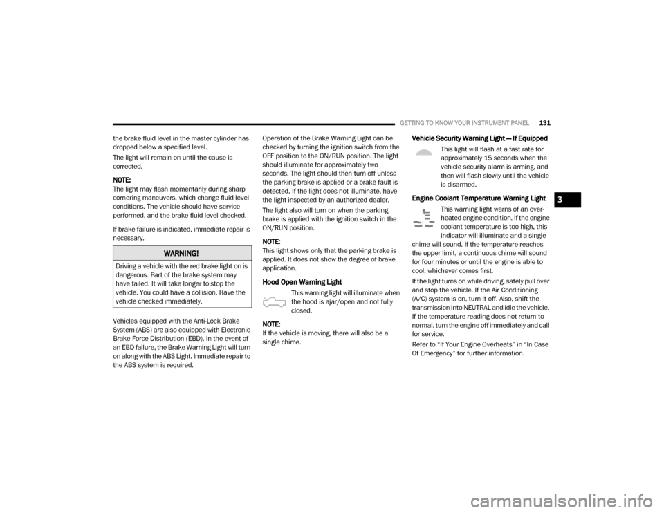
Engine Coolant Temperature Warning Light
This warning light warns of an over -
heated engine condition. If the engine
coolant temperature is too high, this
indicator will illuminate and a single
chime will sound. If the temperature reaches
the upper limit, a continuous chime will sound
for four minutes or until the engine is able to
cool; whichever comes first.
If the light turns on while driving, safely pull over
and stop the vehicle. If the Air Conditioning
(A/C) system is on, turn it off. Also, shift the
transmission into NEUTRAL and idle the vehicle.
If the temperature reading does not return to
normal, turn the engine off immediately and call
for service.
Refer to “If Your Engine Overheats” in “In Case
Of Emergency” for further information.
WARNING!
Driving a vehicle with the red brake light on is
dangerous. Part of the brake system may
have failed. It will take longer to stop the
vehicle. You could have a collision. Have the
vehicle checked immediately.
3
20_DJD2_OM_EN_USC_t.book Page 131
Page 137 of 553
GETTING TO KNOW YOUR INSTRUMENT PANEL135
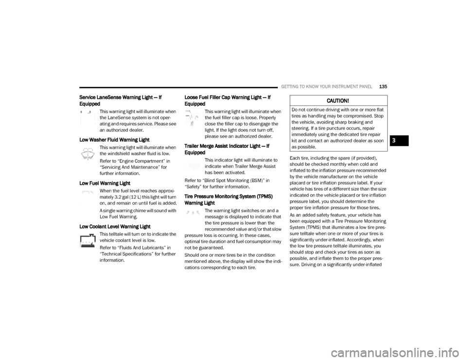
Service LaneSense Warning Light — If
Equipped
This warning light will illuminate when
the LaneSense system is not oper-
ating and requires service. Please see
an authorized dealer.
Low Washer Fluid Warning Light
This warning light will illuminate when
the windshield washer fluid is low.
Refer to “Engine Compartment” in
“Servicing And Maintenance” for
further information.
Low Fuel Warning Light
When the fuel level reaches approxi -
mately 3.2 gal (12 L) this light will turn
on, and remain on until fuel is added.
A single warning chime will sound with
Low Fuel Warning.
Low Coolant Level Warning Light
This telltale will turn on to indicate the
vehicle coolant level is low.
Refer to “Fluids And Lubricants” in
“Technical Specifications” for further
information.
Loose Fuel Filler Cap Warning Light — If
Equipped
This warning light will illuminate when
the fuel filler cap is loose. Properly
close the filler cap to disengage the
light. If the light does not turn off,
please see an authorized dealer.
Trailer Merge Assist Indicator Light — If
Equipped
This indicator light will illuminate to
indicate when Trailer Merge Assist
has been activated.
Refer to “Blind Spot Monitoring (BSM)” in
“Safety” for further information.
Tire Pressure Monitoring System (TPMS)
Warning Light
The warning light switches on and a
message is displayed to indicate that
the tire pressure is lower than the
recommended value and/or that slow
pressure loss is occurring. In these cases,
optimal tire duration and fuel consumption may
not be guaranteed.
Should one or more tires be in the condition
mentioned above, the display will show the indi -
cations corresponding to each tire. Each tire, including the spare (if provided),
should be checked monthly when cold and
inflated to the inflation pressure recommended
by the vehicle manufacturer on the vehicle
placard or tire inflation pressure label. If your
vehicle has tires of a different size than the size
indicated on the vehicle placard or tire inflation
pressure label, you should determine the
proper tire inflation pressure for those tires.
As an added safety feature, your vehicle has
been equipped with a Tire Pressure Monitoring
System (TPMS) that illuminates a low tire pres
-
sure telltale when one or more of your tires is
significantly under-inflated. Accordingly, when
the low tire pressure telltale illuminates, you
should stop and check your tires as soon as
possible, and inflate them to the proper pres -
sure. Driving on a significantly under-inflated
CAUTION!
Do not continue driving with one or more flat
tires as handling may be compromised. Stop
the vehicle, avoiding sharp braking and
steering. If a tire puncture occurs, repair
immediately using the dedicated tire repair
kit and contact an authorized dealer as soon
as possible.
3
20_DJD2_OM_EN_USC_t.book Page 135
Page 212 of 553
210SAFETY
(Continued)
Periodic Safety Checks You Should Make
Outside The Vehicle
Tires
Examine tires for excessive tread wear and
uneven wear patterns. Check for stones, nails,
glass, or other objects lodged in the tread or
sidewall. Inspect the tread for cuts and cracks.
Inspect sidewalls for cuts, cracks, and bulges.
Check the wheel bolts for tightness. Check the
tires (including spare) for proper cold inflation
pressure.
Lights
Have someone observe the operation of brake
lights and exterior lights while you work the
controls. Check turn signal and high beam indi -
cator lights on the instrument panel.
Door Latches
Check for proper closing, latching, and locking.
Fluid Leaks
Check area under the vehicle after overnight
parking for fuel, coolant, oil, or other fluid leaks.
Also, if gasoline fumes are detected or if fuel, or
brake fluid leaks are suspected, the cause
should be located and corrected immediately.
ONLY install floor mats designed to fit your
vehicle. NEVER install a floor mat that
cannot be properly attached and secured to
your vehicle. If a floor mat needs to be
replaced, only use a FCA approved floor
mat for the specific make, model, and year
of your vehicle.
ONLY use the driver’s side floor mat on the
driver’s side floor area. To check for inter -
ference, with the vehicle properly parked
with the engine off, fully depress the accel-
erator, the brake, and the clutch pedal (if
present) to check for interference. If your
floor mat interferes with the operation of
any pedal, or is not secure to the floor,
remove the floor mat from the vehicle and
place the floor mat in your trunk.
ONLY use the passenger’s side floor mat on
the passenger’s side floor area.
WARNING! (Continued)
ALWAYS make sure objects cannot fall or
slide into the driver’s side floor area when
the vehicle is moving. Objects can become
trapped under accelerator, brake, or clutch
pedals and could cause a loss of vehicle
control.
NEVER place any objects under the floor
mat (e.g., towels, keys, etc.). These objects
could change the position of the floor mat
and may cause interference with the accel -
erator, brake, or clutch pedals.
If the vehicle carpet has been removed and
re-installed, always properly attach carpet
to the floor and check the floor mat
fasteners are secure to the vehicle carpet.
Fully depress each pedal to check for inter -
ference with the accelerator, brake, or
clutch pedals then re-install the floor mats.
It is recommended to only use mild soap
and water to clean your floor mats. After
cleaning, always check your floor mat has
been properly installed and is secured to
your vehicle using the floor mat fasteners
by lightly pulling mat.
WARNING! (Continued)
20_DJD2_OM_EN_USC_t.book Page 210