display Ram 3500 2017 Owner's Manual
[x] Cancel search | Manufacturer: RAM, Model Year: 2017, Model line: 3500, Model: Ram 3500 2017Pages: 734, PDF Size: 7.3 MB
Page 407 of 734
Six-Speed Automatic Transmission — 2500/3500
Models Only
The transmission gear position display (located in the
instrument cluster) indicates the transmission gear range.
The gear selector is mounted on the right side of the
steering column. You must press the brake pedal to move
the gear selector out of PARK (refer to “Brake/
Transmission Shift Interlock System” in this section for
further information). To drive, move the gear selector from
PARK or NEUTRAL to the DRIVE position. Pull the gear
selector toward you when shifting into REVERSE or PARK,
or when shifting out of PARK.
The electronically-controlled transmission provides a pre-
cise shift schedule. The transmission electronics are self-
calibrating; therefore, the first few shifts on a new vehicle
may be somewhat abrupt. This is a normal condition, and
precision shifts will develop within a few hundred miles
(kilometers).
Only shift from DRIVE to PARK or REVERSE when the
accelerator pedal is released and the vehicle is stopped. Be
sure to keep your foot on the brake pedal when shifting
between these gears.The transmission gear selector has only PARK, REVERSE,
NEUTRAL, and DRIVE shift positions. Manual downshifts
can be made using the Electronic Range Select (ERS) shift
control (refer to “Electronic Range Select (ERS) Operation”
in this section for further information). Pressing the ERS
(-/+) switches (on the gear selector) while in the DRIVE
position will select the highest available transmission gear,
and will display that gear limit in the instrument cluster as
1, 2, 3, etc. Some models will display both the selected gear
limit, and the actual current gear, while in ERS mode.
Gear Ranges
DO NOT race the engine when shifting from PARK or
NEUTRAL into another gear range.
NOTE:
After selecting any gear range, wait a moment to
allow the selected gear to engage before accelerating. This
is especially important when the engine is cold.
PARK (P)
This range supplements the parking brake by locking the
transmission. The engine can be started in this range.
Never attempt to use PARK while the vehicle is in motion.
Apply the parking brake when leaving the vehicle in this
range.
5
STARTING AND OPERATING 405
Page 409 of 734

WARNING!(Continued)
turn the engine OFF, and remove the key fob. When
the ignition is in the LOCK/OFF (key removal)
position (or, with Keyless Enter-N-Go, when the
ignition is in the OFF mode), the transmission is
locked in PARK, securing the vehicle against un-
wanted movement.
• When leaving the vehicle, always make sure the
ignition is in the OFF mode, remove the key fob from
the vehicle, and lock the vehicle.
• Never leave children alone in a vehicle, or with
access to an unlocked vehicle. Allowing children to
be in a vehicle unattended is dangerous for a number
of reasons. A child or others could be seriously or
fatally injured. Children should be warned not to
touch the parking brake, brake pedal or the trans-
mission gear selector.
• Do not leave the key fob in or near the vehicle (or in
a location accessible to children), and do not leave
the ignition (in a vehicle equipped with Keyless
Enter-N-Go) in the ACC or ON/RUN mode. A child
could operate power windows, other controls, or
move the vehicle.
CAUTION!
• Before moving the transmission gear selector out of
PARK, you must turn the ignition to the ON/RUN
mode, and also press the brake pedal. Otherwise,
damage to the gear selector could result.
• DO NOT race the engine when shifting from PARK
or NEUTRAL into another gear range, as this can
damage the drivetrain.
The following indicators should be used to ensure that you
have engaged the transmission into the PARK position:
• When shifting into PARK, pull the gear selector toward
you and move it all the way counterclockwise until it
stops.
• Release the gear selector and make sure it is fully seated
in the PARK gate.
• Look at the transmission gear position display and
verify that it indicates the PARK position (P).
• With brake pedal released, verify that the gear selector
will not move out of PARK.
5
STARTING AND OPERATING 407
Page 412 of 734

In the event of a momentary problem, the transmission can
be reset to regain all forward gears by performing the
following steps:
1. Stop the vehicle.
2. Shift the transmission into PARK.
3. Turn the ignition to the OFF position.
4. Wait approximately 10 seconds.
5. Restart the engine.
6. Shift into the desired gear range. If the problem is nolonger detected, the transmission will return to normal
operation.
NOTE: Even if the transmission can be reset, we recom-
mend that you visit your authorized dealer at your earliest
possible convenience. Your authorized dealer has diagnos-
tic equipment to determine if the problem could recur.
If the transmission cannot be reset, authorized dealer
service is required.Electronic Range Select (ERS) Operation
The Electronic Range Select (ERS) shift control allows the
driver to limit the highest available gear when the trans-
mission is in DRIVE. For example, if you set the transmis-
sion gear limit to 4 (fourth gear), the transmission will not
shift above fourth gear, but will shift through the lower
gears normally.
You can switch between DRIVE and ERS mode at any
vehicle speed. When the gear selector is in the DRIVE
position, the transmission will operate automatically, shift-
ing between all available gears. Tapping the ERS (-) switch
will activate ERS mode, display the current gear in the
instrument cluster, and set that gear as the top available
gear. Once in ERS mode, tapping (-) or (+) will change the
top available gear.
410 STARTING AND OPERATING
Page 413 of 734
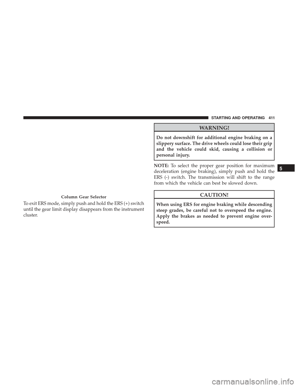
To exit ERS mode, simply push and hold the ERS (+) switch
until the gear limit display disappears from the instrument
cluster.
WARNING!
Do not downshift for additional engine braking on a
slippery surface. The drive wheels could lose their grip
and the vehicle could skid, causing a collision or
personal injury.
NOTE: To select the proper gear position for maximum
deceleration (engine braking), simply push and hold the
ERS (-) switch. The transmission will shift to the range
from which the vehicle can best be slowed down.
CAUTION!
When using ERS for engine braking while descending
steep grades, be careful not to overspeed the engine.
Apply the brakes as needed to prevent engine over-
speed.
Column Gear Selector
5
STARTING AND OPERATING 411
Page 440 of 734

AIR SUSPENSION SYSTEM (1500 MODELS) —
IF EQUIPPED
Description
The air suspension system provides full time load leveling
capability along with the benefit of being able to adjust
vehicle height by the push of a button.
1 — Up Button
2 — Down Button
3 — Entry/Exit Mode Indicator (Customer selectable)
4 — Normal Ride Height Indicator (Customer selectable)
5 — Off-Road 1 Indicator (Customer selectable)
6 — Off-Road 2 Indicator (Customer selectable)
NOTE:The vehicle will automatically enter Aero Mode
when the vehicle speed remains between 62 mph (100 km/h)
and 66 mph (106 km/h) for greater than 20 seconds or if the
vehicle speed exceeds 66 mph (106 km/h).
• Normal Ride Height (NRH) – This is the standard
position of the suspension and is meant for normal
driving.
• Off-Road 1 (OR1) (Raises the vehicle approximately 1
in [26 mm]) – This position should be the primary
position for all off-road driving until Off Road 2 (OR2) is
needed. A smoother and more comfortable ride will
result. To enter OR1, push the “Up” button once from
the NRH position while the vehicle speed is below
35 mph (56 km/h). When in the OR1 position, if the
vehicle speed remains between 40 mph (64 km/h) and
50 mph (80 km/h) for greater than 20 seconds or if the
vehicle speed exceeds 50 mph (80 km/h), the vehicle
will be automatically lowered to NRH. Off-Road 1 may
not be available due to vehicle payload, an instrument
cluster message will be displayed when this occurs.
Refer to “Instrument Cluster Display” in “Understand-
ing Your Instrument Panel” for further information.
Air Suspension Switch
438 STARTING AND OPERATING
Page 441 of 734
![Ram 3500 2017 Owners Manual •Off-Road 2 (OR2) (Raises the vehicle approximately
2 in [51 mm]) –
This position is intended for off-roading
use only where maximum ground clearance is required.
To enter OR2, push the “Up” b Ram 3500 2017 Owners Manual •Off-Road 2 (OR2) (Raises the vehicle approximately
2 in [51 mm]) –
This position is intended for off-roading
use only where maximum ground clearance is required.
To enter OR2, push the “Up” b](/img/34/12583/w960_12583-440.png)
•Off-Road 2 (OR2) (Raises the vehicle approximately
2 in [51 mm]) –
This position is intended for off-roading
use only where maximum ground clearance is required.
To enter OR2, push the “Up” button twice from the NRH
position or once from the OR1 position while vehicle
speed is below 20 mph (32 km/h). While in OR2, if the
vehicle speed exceeds 25 mph (40 km/h) the vehicle
height will be automatically lowered to OR1. Off-Road 2
may not be available due to vehicle payload, an instru-
ment cluster message will be displayed when this occurs.
Refer to “Instrument Cluster Display” in “Understanding
Your Instrument Panel” for further information.
CAUTION!
If the vehicle is in OFFROAD1 or OFFROAD2 setting,
be aware of your surroundings, you may not have the
clearance required for certain areas and vehicle dam-
age may occur.
• Aero Mode (Lowers the vehicle approximately .6 in
[15 mm]) –
This position provides improved aerodynam-
ics by lowering the vehicle. The vehicle will automatically
enter Aero Mode when the vehicle speed remains between
62 mph (100 km/h) and 66 mph (106 km/h) for greater
than 20 seconds or if the vehicle speed exceeds 66 mph (106 km/h). The vehicle will return to NRH from Aero
Mode if the vehicle speed remains between 30 mph
(48 km/h) and 35 mph (56 km/h) for greater than 20 sec-
onds or if the vehicle speed falls below 30 mph (48 km/h).
NOTE:
Automatic Aero Mode may be disabled through
vehicle settings in the instrument cluster display when
equipped with Uconnect 3.0, or your Uconnect Radio when
equipped with Uconnect 5.0, 8.4A, or 8.4AN. Refer to
“Instrument Cluster Display” in “Understanding Your
Instrument Panel” or “Uconnect Settings” in “Understand-
ing Your Instrument Panel” for further information.
• Entry/Exit Mode (Lowers the vehicle approximately
2 in [51 mm]) – This position lowers the vehicle for
easier passenger entry and exit as well as lowering the
rear of the vehicle for easier loading and unloading of
cargo. To enter Entry/Exit Mode, push the “Down”
button once from the NRH while the vehicle speed is
below 33 mph (53 km/h). Once the vehicle speed goes
below 15 mph (24 km/h) the vehicle height will begin to
lower. If the vehicle speed remains between 15 mph
(24 km/h) and 25 mph (40 km/h) for greater than
60 seconds, or the vehicle speed exceeds 25 mph
(40 km/h) the Entry/Exit change will be cancelled. To
return to Normal Height Mode, push the “Up” button
5
STARTING AND OPERATING 439
Page 442 of 734

once while in Entry/Exit or drive the vehicle over
15 mph (24 km/h). Entry/Exit mode may not be avail-
able due to vehicle payload, an instrument cluster
message will be displayed when this occurs. Refer to
“Instrument Cluster Display” in “Understanding Your
Instrument Panel” for further information.
NOTE: Entry/Exit mode may be achieved using your key
fob for easier entry/loading. Refer to “A Word About Your
Keys” in “Things To Know Before Starting Your Vehicle”
for further information.
CAUTION!
When in ENTRY/EXIT setting, be aware of your sur-
roundings, you may not have the clearance required for
certain areas and vehicle damage may occur.
The system requires that the ignition be in ON/RUN
position or the engine running for all user requested
changes. When lowering the vehicle all of the doors, must
be closed. If a door is opened at any time while the vehicle
is lowering the change will not be completed until the open
door(s) is closed. This system uses a lifting and lowering pattern which
keeps the headlights from incorrectly shining into oncom-
ing traffic. When raising the vehicle, the rear of the vehicle
will move up first and then the front. When lowering the
vehicle, the front will move down first and then the rear.
After the engine is turned off, it may be noticed that the air
suspension system operates briefly, this is normal. The
system is correcting the position of the vehicle to ensure a
proper appearance.
To assist with changing a spare tire, the air suspension
system has a feature which allows the automatic leveling to
be disabled. Refer to “Instrument Cluster Display” in
“Understanding Your Instrument Panel” for further infor-
mation.
NOTE:
If equipped with a touch screen radio all enabling/
disabling of air suspension features must be done through
the radio. Refer to “Uconnect Settings” in “Understanding
Your Instrument Panel” for further information.
440 STARTING AND OPERATING
Page 443 of 734
WARNING!
The air suspension system uses a high pressure vol-
ume of air to operate the system. To avoid personal
injury or damage to the system, see your authorized
dealer for service.
Air Suspension Modes
The Air Suspension system has multiple modes to protect
the system in unique situations:
AERO Mode
To improve aerodynamics, the air suspension system has a
feature which will put the vehicle into AERO height
automatically. Refer to “Instrument Cluster Display” in
“Understanding Your Instrument Panel” for further infor-
mation.
NOTE:This mode is intended to be enabled with engine
running. Tire/Jack Mode
To assist with changing a tire, the air suspension system
has a feature which allows the automatic leveling to be
disabled. Refer to “Instrument Cluster Display” in “Under-
standing Your Instrument Panel” or “Uconnect Settings” in
“Understanding Your Instrument Panel” if equipped with
a touch screen radio for further information.
NOTE:
This mode is intended to be enabled with engine
running.
Transport Mode
For towing your vehicle with four wheels off the road, the
air suspension system has a feature which will put the
vehicle into Entry/Exit height and disable the automatic
load leveling system. Refer to “Instrument Cluster Dis-
play” in “Understanding Your Instrument Panel” or
“Uconnect Settings” in “Understanding Your Instrument
Panel” if equipped with a touch screen radio for further
information.
NOTE: This mode is intended to be enabled with engine
running.
5
STARTING AND OPERATING 441
Page 444 of 734
Wheel Alignment Mode
Before performing a wheel alignment, this mode must be
enabled. Refer to “Instrument Cluster Display” in “Under-
standing Your Instrument Panel” or “Uconnect Settings” in
“Understanding Your Instrument Panel” if equipped with
a touch screen radio for further information.
NOTE:This mode is intended to be enabled with engine
running.
Protection Strategy
In order to “protect” the air suspension system, the vehicle
will disable load leveling as required (suspension over-
loaded, battery charge low, etc.). Load leveling will auto-
matically resume as soon as system operation requirements
are met. See your authorized dealer if system does not
resume.
NOTE: If towing with air suspension refer to “Trailer
Towing” in “Starting And Operating” for further informa-
tion.Instrument Cluster Display Messages
When the appropriate conditions exist, a message will
appear in the instrument cluster display. Refer to “Instru-
ment Cluster Display” in “Understanding Your Instrument
Panel” for further information.
An audible chime will be heard whenever a system error
has been detected.
See your authorized dealer for system service if normal
operation does not resume.
442 STARTING AND OPERATING
Page 446 of 734
Automatic height changes will occur based on vehicle
speed and the current vehicle height. The indicator lamps
and instrument cluster display messages will operate the
same for automatic changes and user requested changes.
•Off-Road 2 (OR2) – Indicator lamps 3, 4, 5 and 6 will be
illuminated when the vehicle is in OR2.
• Off-Road 1 (OR1) – Indicator lamps 3, 4 and 5 will be
illuminated when the vehicle is in OR1.
• Normal Ride Height (NRH)/Aero Mode – Indicator
lamps 3 and 4 will be illuminated when the vehicle is in
this position.
• Entry/Exit Mode – Indicator lamp 3 will be illuminated
when the vehicle is in Entry Exit Mode. Entry/Exit
mode can be requested up to 33 mph (53 km/h). If
vehicle speed is reduced to, and kept below, 15 mph
(24 km/h) indicator lamp 4 will flash and indicator lamp
3 will remain solid until Entry/Exit Mode is achieved at
which point indicator lamp 4 will turn off.
•
Transport Mode – No indicator lamps will be illuminated.
Transport Mode is disabled by driving the vehicle.
• Tire/Jack Mode – Indicator lamps 3 and 6 will be
illuminated. Tire/Jack Mode is disabled by driving the
vehicle.
• Wheel Alignment Mode – Indicator lamps 3 and 4 will
be illuminated. Wheel Alignment Mode is disabled by
driving the vehicle.
AIR SUSPENSION SYSTEM (REBEL MODELS
ONLY) — IF EQUIPPED
Description
The air suspension system provides full time load leveling
capability along with the benefit of being able to adjust
vehicle height by the push of a button.
444 STARTING AND OPERATING